Section 1. NAVAID Use Limitations
4-1-1. ALTITUDE AND DISTANCE LIMITATIONS
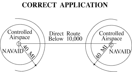
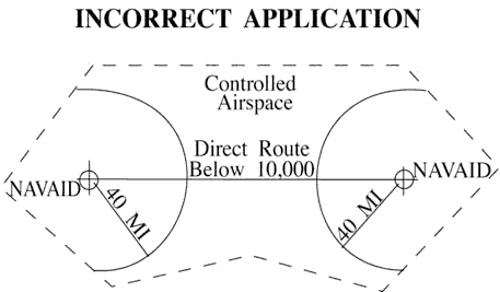
When specifying a route other than an established airway or route, do not exceed the limitations in the table on any portion of the route which lies within controlled airspace. (For altitude and distance limitations, see TBL 4-1-1, TBL 4-1-2, and TBL 4-1-3) (For correct application of altitude and distance limitations see FIG 4-1-1 and FIG 4-1-2.)
| Class | Altitude | Distance (miles) |
|---|---|---|
| T | 12,000 and below | 25 |
| L | Below 18,000 | 40 |
| H | Below 14,500 | 40 |
| H | 14,500 - 17,999 | 100 |
| H | 18,000 - FL 450 | 130 |
| H | Above FL 450 | 100 |
| Class | Power (watts) | Distance (miles) |
|---|---|---|
| CL | Under 25 | 15 |
| MH | Under 50 | 25 |
| H | 50 - 1,999 | 50 |
| HH | 2000 or more | 75 |
| Height (feet) above transmitter | Distance (miles from transmitter) |
|---|---|
| 4,500 | 10 (for glideslope) |
| 4,500 | 18 (for localizer) |
| *Use the current flight check height/altitude limitations if different from the above minima. | |
4-1-2. EXCEPTIONS
Altitude and distance limitations need not be applied when any of the following conditions are met:
-
Routing is initiated by ATC or requested by the pilot and radar monitoring is provided.
EXCEPTION: GNSS equipped aircraft /G, /L, /S, and /V not on a random impromptu route.
- NOTE:
- 1. Except for GNSS equipped aircraft /G, /L, /S, and /V, not on a random impromptu route, Paragraph 5-5-1, Application, requires radar separation be provided to RNAV aircraft operating at and below FL450 on Q routes or random RNAV routes, excluding oceanic airspace.
- 2. When a clearance is issued beyond the altitude and/or distance limitations of a NAVAID, in addition to being responsible for maintaining separation from other aircraft and airspace, the controller is responsible for providing aircraft with information and advice related to significant deviations from the expected flight path.
- REFERENCE
- FAA Order JO 7110.65, Para 2-1-3, Procedural Preference.
- FAA Order JO 7110.65, Para 4-4-2, Route Structure Transitions.
- FAA Order JO 7110.65, Para 5-1-6, Deviation Advisories.
- FAA Order JO 7110.65, Para 5-5-1, Application.
- FAA Order JO 7110.65, Para 6-5-4, Minima Along Other Than Established Airways or Routes.
- AIM, Para 5-1-8c, Direct Flights.
- AIM, Para 5-1-8d, Area Navigation (RNAV).
- P/CG Term - Global Navigation Satellite System (GNSS)[ICAO].
- Operational necessity requires and approval has been obtained from the Frequency Management and Flight Inspection Offices to exceed them.
- Requested routing is via an MTR.
4-1-3. CROSSING ALTITUDE
Use an altitude consistent with the limitations of the aid when clearing an aircraft to cross or hold at a fix.
4-1-4. VFR-ON-TOP
Use a route not meeting service volume limitations only if an aircraft requests to operate “VFR-on-top” on this route.
- NOTE:
- Aircraft equipped with TACAN only are expected to:
- 1. Define route of flight between TACAN or VORTAC NAVAIDs in the same manner as VOR-equipped aircraft.
- 2. Except in Class A airspace, submit requests for “VFR-on-top” flight where insufficient TACAN or VORTAC NAVAIDs exist to define the route.
4-1-5. FIX USE
Request aircraft position reports only over fixes shown on charts used for the altitude being flown, except as follows:
NOTE: Waypoints filed in random RNAV routes automatically become compulsory reporting points for the flight unless otherwise advised by ATC.
- Unless the pilot requests otherwise, use only those fixes shown on high altitude en route charts, high altitude instrument approach procedures charts, and SID charts when clearing military turbojet single-piloted aircraft.
- Except for military single-piloted turbojet aircraft, unpublished fixes may be used if the name of the NAVAID and, if appropriate, the radial/course/ azimuth and frequency/channel are given to the pilot. An unpublished fix is defined as one approved and planned for publication which is not yet depicted on the charts or one which is used in accord with the following:
- REFERENCE
- FAA Order 8260.3, United States Standard for Terminal Instrument Procedures (TERPS), Chapter 17, Basic Holding Criteria.
- Unpublished fixes are formed by the en route radial and either a DME distance from the same NAVAID or an intersecting radial from an off-route VOR/VORTAC/TACAN. DME must be used in lieu of off-route radials, whenever possible.
- Except where known signal coverage restrictions exist, an unpublished fix may be used for ATC purposes if its location does not exceed NAVAID altitude and distance limitation, and when off-route radials are used, the angle of divergence meets the criteria prescribed below.
NOTE: Unpublished fixes should not negate the normal use of published intersections. Frequent routine use of an unpublished fix would justify establishing a fix.
- Do not hold aircraft at unpublished fixes below the lowest assignable altitude dictated by terrain clearance for the appropriate holding pattern airspace area (template) regardless of the MEA for the route being flown.
- When the unpublished fix is located on an off-route radial and the radial providing course guidance, it must be used consistent with the following divergence angles:
- (a) When holding operations are involved with respect to subparas (b) and (c) below, the angle of divergence must be at least 45 degrees.
- (b) When both NAVAIDs involved are located within 30 NM of the unpublished fix, the minimum divergence angle is 30 degrees.
- (c) When the unpublished fix is located over 30 NM from the NAVAID generating the off-course radial, the minimum divergence angle must increase 1 degree per NM up to 45 NM; e.g., 45 NM would require 45 degrees.
- (d) When the unpublished fix is located beyond 45 NM from the NAVAID generating the off-course radial, the minimum divergence angle must increase 1/2 degree per NM; e.g., 130 NM would require 88 degrees.
- Fixes contained in the route description of MTRs are considered filed fixes.
- TACAN-only aircraft (type suffix M, N, or P) possess TACAN with DME, but no VOR or LF navigation system capability. Assign fixes based on TACAN or VORTAC facilities only.
NOTE: TACAN-only aircraft can never be held overhead the NAVAID, be it TACAN or VORTAC.
- DME fixes must not be established within the no-course signal zone of the NAVAID from which inbound holding course information would be derived.
Section 2. Clearances
4-2-1. CLEARANCE ITEMS
Issue the following clearance items, as appropriate, in the order listed below:
- Aircraft identification.
-
Clearance limit.
-
When the clearance limit is an airport, the word “airport” must follow the airport name.
- PHRASEOLOGY
- CLEARED TO (destination) AIRPORT.
-
When the clearance limit is a NAVAID, and the NAVAID type is known, the type of NAVAID must follow the NAVAID
name.
- PHRASEOLOGY
- CLEARED TO (NAVAID name and type).
-
When the clearance limit is an intersection or waypoint, and the type is known, the type must follow the
intersection or waypoint name.
- PHRASEOLOGY
- CLEARED TO (intersection or waypoint name and type).
-
When the clearance limit is an airport, the word “airport” must follow the airport name.
- Standard Instrument Departure (SID) or vectors, where applicable.
- Route of flight including ADR/ADAR/AAR when applied.
- Altitude data in the order flown.
- Mach number, if applicable.
-
USAF. When issuing a clearance to an airborne aircraft containing an altitude
assignment, do not include more than one of the following in the same transmission:
- Frequency change.
- Transponder change.
- Heading.
- Altimeter setting.
- Traffic information containing an altitude.
- Holding instructions.
- Any special information.
- Frequency and beacon code information.
4-2-2. CLEARANCE PREFIX
- Prefix a clearance, information, or a request for information which will be relayed to an aircraft through a non-ATC facility by stating “A-T-C clears,” “A-T-C advises,” or “A-T-C requests.”
- Flight service stations and ARTCC Flight Data Units must prefix a clearance with the appropriate phrase: “ATC clears,” “ATC advises,” etc.
4-2-3. DELIVERY INSTRUCTIONS
Issue specific clearance delivery instructions, if appropriate.
4-2-4. CLEARANCE RELAY
Relay clearances verbatim.
4-2-5. ROUTE OR ALTITUDE AMENDMENTS
- Amend route of flight in a previously issued clearance by one of the following:
- State which portion of the route is being amended and then state the amendment.
- PHRASEOLOGY
- CHANGE (portion of route) TO READ (new portion of route).
- State the amendment to the route and then state that the rest of the route is unchanged.
- PHRASEOLOGY
- (Amendment to route), REST OF ROUTE UNCHANGED.
- Issue a clearance “direct” to a point on the previously issued route.
- PHRASEOLOGY
- CLEARED DIRECT (fix,waypoint).
- Or
- CLEARED DIRECT (destination) AIRPORT.
NOTE: Clearances authorizing “direct” to a point on a previously issued route do not require the phrase “rest of route unchanged.” However, it must be understood where the previously cleared route is resumed. When necessary, “rest of route unchanged” may be used to clarify routing.
- Issue the entire route by stating the amendment.
- EXAMPLE
- (Cessna 21A has been cleared to the Airville Airport via V41 Delta VOR V174 Alfa VOR, direct Airville Airport, maintain 9000. After takeoff, the aircraft is rerouted via V41 Frank intersection, V71 Delta VOR, V174 Alfa VOR. The controller issues one of the following as an amended clearance):
- 1. “Cessna Two One Alfa change Victor Forty-One Delta to read Victor Forty-One Frank, Victor Seventy-One Delta.”
- 2. “Cessna Two One Alfa cleared via Victor Forty-One Frank, Victor Seventy-One Delta, rest of route unchanged.”
- 3. “Cessna Two One Alfa cleared via Victor Forty-One Frank, Victor Seventy-One Delta, Victor One Seventy-Four Alfa V-O-R, direct Airville airport, maintain Niner Thousand.”
- State which portion of the route is being amended and then state the amendment.
- When route or altitude in a previously issued clearance is amended, restate all applicable altitude restrictions.
- EXAMPLE
- 1. (A departing aircraft is cleared to cross Ollis intersection at or above 3,000; Gordonsville VOR at or above 12,000; maintain FL 200. Shortly after departure the altitude to be maintained is changed to FL 240. Because altitude restrictions remain in effect, the controller issues an amended clearance as follows):
“Amend altitude. Cross Ollis intersection at or above Three Thousand; cross Gordonsville V-O-R at or above One Two Thousand; maintain Flight Level Two Four Zero.”
(Shortly after departure, altitude restrictions are no longer applicable, the controller issues an amended clearance as follows):
“Climb and maintain Flight Level Two Four Zero.”
- 2. (An aircraft is cleared to climb via a SID with published altitude restrictions. Shortly after departure the top altitude is changed to FL 230 and compliance with the altitude restrictions is still required, the controller issues an amended clearance as follows):
“Climb via SID except maintain Flight Level Two Three Zero.”
- NOTE:
- 1. Restating previously issued altitude to “maintain” is an amended clearance. If altitude to “maintain” is changed or restated, whether prior to departure or while airborne and previously issued altitude restrictions are omitted, altitude restrictions are canceled, including SID/STAR altitude restrictions if any.
- 2. Crossing altitudes and speed restrictions on Obstacle Departure Procedure/s (ODP/s) cannot be canceled or amended by ATC.
- Issue an amended clearance if a speed restriction is declined because it cannot be complied with concurrently with a previously issued altitude restriction.
- EXAMPLE
- (An aircraft is cleared to cross Gordonsville VOR at 11,000. Shortly thereafter he/she is cleared to reduce his/her airspeed to 300 knots. The pilot informs the controller he/she is unable to comply with both clearances simultaneously. The controller issues an amended clearance as follows):
“Cross Gordonsville VOR at One One Thousand. Then, reduce speed to Three Zero Zero.”
NOTE: The phrase “do the best you can” or comparable phrases are not valid substitutes for an amended clearance with altitude or speed restrictions.
- Air traffic control specialists should avoid route and/or altitude changes for aircraft participating in the North American Route Program (NRP) and that are displaying “NRP” in the remarks section of their flight plan.
NOTE: Air traffic control specialists retain the latitude necessary to tactically resolve conflicts. Every effort should be made to ensure the aircraft is returned to the original filed flight plan/altitude as soon as conditions warrant.
- REFERENCE
- FAA Order JO 7110.65, Para 2-1-4, Operational Priority.
- FAA Order JO 7110.65, Para 2-2-15, North American Route Program (NRP) Information.
- FAA Order JO 7110.65, Para 2-3-2, En Route Data Entries.
- FAA Order JO 7210.3, Chapter 18, Section 17, North American Route Program.
4-2-6. THROUGH CLEARANCE
You may clear an aircraft through intermediate stops.
- PHRASEOLOGY
- CLEARED THROUGH (airport) TO (fix).
4-2-7. ALTRV CLEARANCE
Use the phrase “via approved altitude reservation flight plan,” if the aircraft will operate in an approved ALTRV.
- PHRASEOLOGY
- VIA APPROVED ALTITUDE RESERVATION (mission name) FLIGHT PLAN.
NOTE: An ALTRV normally includes the departure, climb, cruise, and arrival phases of flight up to and including holding pattern or point/time at which ATC provides separation between aircraft.
4-2-8. IFR-VFR AND VFR-IFR FLIGHTS
interpretation 25- Clear an aircraft planning IFR operations for the initial part of flight and VFR for the latter part to the fix at which the IFR part ends.
- Treat an aircraft planning VFR for the initial part of flight and IFR for the latter part as a VFR departure. Issue a clearance to this aircraft when it requests IFR clearance approaching the fix where it proposes to start IFR operations. The phraseology CLEARED TO (destination) AIRPORT AS FILED may be used with abbreviated departure clearance procedures.
- When an aircraft changes from VFR to IFR, the controller must assign a beacon code to Mode-C equipped aircraft that will allow MSAW alarms.
- When VFR aircraft operating below the minimum altitude for IFR operations requests an IFR clearance and the pilot informs you, or you are aware, that they are unable to climb in VFR conditions to the minimum IFR altitude:
- Before issuing a clearance, ask if the pilot is able to maintain terrain and obstruction clearance during a climb to the minimum IFR altitude.
- PHRASEOLOGY
- (Aircraft call sign), ARE YOU ABLE TO MAINTAIN YOUR OWN TERRAIN AND OBSTRUCTION CLEARANCE UNTIL REACHING (appropriate MVA/MIA/MEA/OROCA)
NOTE: Pilots of pop-up aircraft are responsible for terrain and obstacle clearance until reaching minimum instrument altitude (MIA) or minimum en route altitude (MEA). Pilot compliance with an approved FAA procedure or an ATC instruction transfers that responsibility to the FAA; therefore, do not assign (or imply) specific course guidance that will (or could) be in effect below the MIA or MEA.
- EXAMPLE
- “November Eight Seven Six, are you able to provide your own terrain and obstruction clearance between your present altitude and six thousand feet?”
- If the pilot is able to maintain their own terrain and obstruction clearance, issue the appropriate IFR clearance as prescribed in Para 4-2-1, Clearance Items, and Para 4-5-6, Minimum En Route Altitudes.
- If the pilot states that they are unable to maintain terrain and obstruction clearance, instruct the pilot to maintain VFR and to state intentions.
- If appropriate, apply the provisions of Para 10-2-7, VFR Aircraft In Weather Difficulty, or Para 10-2-9, Radar Assistance Techniques, as necessary.
- Before issuing a clearance, ask if the pilot is able to maintain terrain and obstruction clearance during a climb to the minimum IFR altitude.
4-2-9. CLEARANCE ITEMS
The following guidelines must be utilized to facilitate the processing of airfile aircraft:
- Ensure the aircraft is within your area of jurisdiction unless otherwise coordinated.
- Obtain necessary information needed to provide IFR service.
- Issue clearance to destination, short range clearance, or an instruction to the pilot to contact an FSS if the flight plan cannot be processed. If clearance is to destination airport, the phraseology CLEARED TO (destination) AIRPORT must be used. If clearance is to a NAVAID, state the name of the NAVAID followed by the type of NAVAID, if the type is known. If clearance is to an intersection or waypoint and the type is known, the type must follow the intersection or waypoint name.
NOTE: These procedures do not imply that the processing of airfiles has priority over another ATC duty to be performed.
4-2-10. CANCELLATION OF IFR FLIGHT PLAN
- If necessary, before instructing an IFR aircraft arriving at an airport not served by an air traffic control tower or flight service station to change to the common traffic advisory frequency, provide the pilot with instructions on how to cancel his/her IFR flight plan.
- Airports with an air/ground communications station:
- PHRASEOLOGY
- (Call sign) REPORT CANCELLATION OF IFR ON (frequency).
- Airports without an air/ground communications station:
- PHRASEOLOGY
- (Call sign) REPORT CANCELLATION OF IFR THIS FREQUENCY OR WITH FLIGHT SERVICE.
- Or
- (Call sign) REPORT CANCELLATION OF IFR THIS FREQUENCY OR WITH (FSS serving the area or the ATC controlling facility).
- EXAMPLE
- “N13WA report cancellation of IFR this frequency or with McAlester Radio.”
- Airports with an air/ground communications station:
- Respond to a pilot's cancellation of his/her IFR flight plan as follows:
- PHRASEOLOGY
- (Call sign) IFR CANCELLATION RECEIVED.
Section 3. Departure Procedures
4-3-1. DEPARTURE TERMINOLOGY
Avoid using the term “takeoff” except to actually clear an aircraft for takeoff or to cancel a takeoff clearance. Use such terms as “depart,” “departure,” or “fly” in clearances when necessary.
4-3-2. DEPARTURE CLEARANCES
interpretation 4Include the following items in IFR departure clearances:
NOTE: When considered necessary, controllers or pilots may initiate read backs of a clearance. Some pilots may be required by company rule to do so.
- Always include the airport of departure when issuing a departure clearance for relay to an aircraft by an FSS, dispatcher, etc.
-
Clearance Limit.
-
Specify the destination airport when practicable, even though it is outside controlled airspace. Issue short
range clearances as provided for in any procedures established for their use.
-
(a) When the clearance limit is an airport, the word “airport” must follow the airport name.
- PHRASEOLOGY
- CLEARED TO (destination) AIRPORT
-
(b) When the clearance limit is a NAVAID and the NAVAID type is known, the type of NAVAID must follow the
NAVAID name.
- PHRASEOLOGY
- CLEARED TO (NAVAID name and type)
-
(c) When the clearance limit is an intersection or waypoint and the type is known, the type must follow
the intersection or waypoint name.
- PHRASEOLOGY
- CLEARED TO (intersection or waypoint name and type)
-
(a) When the clearance limit is an airport, the word “airport” must follow the airport name.
-
For Air Force One (AF1) operations, do not specify the destination airport.
NOTE: Presidential detail is responsible for ensuring the accuracy of the destination airport.
- PHRASEOLOGY
- DESTINATION AS FILED.
-
Specify the destination airport when practicable, even though it is outside controlled airspace. Issue short
range clearances as provided for in any procedures established for their use.
-
Departure Procedures.
-
Specify direction of takeoff/turn or initial heading to be flown after takeoff as follows:
-
(a) Locations with Airport Traffic Control Service-Specify direction of takeoff/turn or initial heading as
necessary, consistent with published:
- (1) Departure Procedures (DP). If an aircraft is vectored off a published Standard Instrument Departure (SID) or Obstacle Departure Procedure (ODP), that vector cancels the DP and ATC becomes responsible for separation from terrain and/or obstructions. IFR aircraft must be assigned an altitude.
- (2) Diverse Vector Areas (DVA). The assignment of an initial heading using a DVA can be given to the pilot as part of the initial clearance, but must be given no later than with the takeoff clearance. Once airborne, an aircraft assigned headings within the DVA can be vectored below the MVA/MIA. Controllers cannot interrupt an aircraft's climb in the DVA until the aircraft is at or above the MVA/MIA.
- NOTE:
- 1. It is important for controllers to understand that there can be differences in published climb gradients applicable to individual departure procedures serving the same airport or runway. Assigning a different departure procedure without the pilot being able to re-brief may result in the pilot rejecting the new procedure.
- 2. When a departure clearance includes a SID, concurrent use of a diverse vector area (DVA) is not permitted.
-
(b) Locations without Airport Traffic Control Service, but within a Class E surface area* specify
direction of takeoff/turn or initial heading if necessary. Obtain/solicit the pilot's concurrence
concerning a turn or heading before issuing them in a clearance.
NOTE: Direction of takeoff and turn after takeoff can be obtained/solicited directly from the pilot, or relayed by an FSS, dispatcher, etc., as obtained/solicited from the pilot.
- (c) At all other airports Do not specify direction of takeoff/turn after takeoff. If necessary to specify an initial heading to be flown after takeoff, issue the initial heading so as to apply only within controlled airspace.
-
(a) Locations with Airport Traffic Control Service-Specify direction of takeoff/turn or initial heading as
necessary, consistent with published:
-
Where an ODP has been published for a location and pilot compliance is necessary to ensure separation, include
the procedure as part of the ATC clearance. Additionally, when an ODP is included in the clearance and the
Visual Climb over Airport (VCOA) is requested by the pilot or assigned by ATC when it is the only procedure
published in the ODP, include an instruction to remain within the published visibility of the VCOA.
- EXAMPLE
- "Depart via the (airport name)(runway number) obstacle departure procedure. Remain within (number of miles) miles of the (airport name) during visual climb” if applicable."
- or
- "Depart via the (graphic ODP name) obstacle departure procedure. Remain within (number of miles) miles of the (airport name) during visual climb" if applicable.
- NOTE:
- 1. Pilots will advise ATC of their intent to use the VCOA option when requesting their IFR clearance.
- 2. Some aircraft are required by 14 CFR 91.175 to depart a runway under IFR using the ODP absent other instructions from ATC.
- 3. IFR takeoff minimums and obstacle departure procedures are prescribed for specific airports/runways and published in either a textual, or graphic form with the label (OBSTACLE) in the procedure title, and documented on an appropriate FAA Form 8260. To alert pilots of their existence, instrument approach procedure charts are annotated with a symbol:

-
Compatibility with a procedure issued may be verified by asking the pilot if items obtained/solicited will
allow him/her to comply with local traffic pattern, terrain, or obstruction avoidance.
- PHRASEOLOGY
- FLY RUNWAY HEADING.
- DEPART (direction or runway).
- TURN LEFT/RIGHT.
- WHEN ENTERING CONTROLLED AIRSPACE (instruction), FLY HEADING (degrees) UNTIL REACHING (altitude, point, or fix) BEFORE PROCEEDING ON COURSE.
- FLY A (degree) BEARING/AZIMUTH FROM/TO (fix) UNTIL (time),
- or
- UNTIL REACHING (fix or altitude),
- and if required,
- BEFORE PROCEEDING ON COURSE.
- EXAMPLE
- “Verify right turn after departure will allow compliance with local traffic pattern,”or “Verify this clearance will allow compliance with terrain or obstruction avoidance.”
NOTE: If a published IFR departure procedure is not included in an ATC clearance, compliance with such a procedure is the pilot's prerogative.
-
SIDs:
-
(a) Assign a SID (including transition if necessary). Assign a ADR/ADAR, when applicable or the route
filed by the pilot, when a SID is not established for the departure route to be flown, or the pilot has
indicated that he/she does not wish to use a SID.
NOTE: Departure procedure descriptive text contained within parentheses (for example, “Jimmy One (RNAV) Departure”) is not included in departure clearance phraseology.
- PHRASEOLOGY
- (SID name and number) DEPARTURE.
- (SID name and number) DEPARTURE, (transition name) TRANSITION.
- EXAMPLE
- “Stroudsburg One Departure.”
- “Stroudsburg One Departure, Sparta Transition.”
NOTE: If a pilot does not wish to use a SID issued in an ATC clearance, or any other SID published for that location, he/she is expected to advise ATC.
-
(b) If it is necessary to assign a crossing altitude which differs from the SID altitude emphasize the
change to the pilot.
- PHRASEOLOGY
- (SID name and number) DEPARTURE, EXCEPT CROSS (revised altitude information).
- EXAMPLE
- “Stroudsburg One Departure, except cross Quaker at five thousand.”
- “Astoria Two Departure, except cross Astor waypoint at six thousand.”
-
(c) Specify altitudes when they are not included in the SID.
- PHRASEOLOGY
- (SID name and number) DEPARTURE. CROSS (fix) AT (altitude).
- EXAMPLE
- “Stroudsburg One Departure. Cross Jersey intersection at four thousand. Cross Range intersection at six thousand.”
- “Engle Two departure. Cross Pilim waypoint at or above five thousand. Cross Engle waypoint at or above seven thousand. Cross Gorge waypoint at niner thousand.”
-
(a) Assign a SID (including transition if necessary). Assign a ADR/ADAR, when applicable or the route
filed by the pilot, when a SID is not established for the departure route to be flown, or the pilot has
indicated that he/she does not wish to use a SID.
-
Specify direction of takeoff/turn or initial heading to be flown after takeoff as follows:
-
Route of flight. Specify one or more of the following:
- Airway, route, course, heading, azimuth, arc, or vector.
-
The routing a pilot can expect if any part of the route beyond a short range clearance limit differs from that
filed.
- PHRASEOLOGY
- EXPECT FURTHER CLEARANCE VIA (airways, routes, or fixes.)
-
Altitude. Use one of the following in the order of preference listed.
NOTE: Turbojet aircraft equipped with afterburner engines may occasionally be expected to use afterburning during their climb to the en route altitude. When so advised by the pilot, the controller may be able to plan his/her traffic to accommodate the high performance climb and allow the pilot to climb to his/her planned altitude without restriction.
- REFERENCE
- P/CG, Climb Via, Top Altitude.
-
To the maximum extent possible, Air Force One will be cleared unrestricted climb to:
- (a) 9,000' AGL or higher.
- (b) If unable 9,000' AGL or higher, then the highest available altitude below 9,000' AGL.
- Assign the altitude requested by the pilot.
-
Assign an altitude, as near as possible to the altitude requested by the pilot, and
- (a) Inform the pilot when to expect clearance to the requested altitude unless instructions are contained in the specified SID, or
- (b) If the requested altitude is not expected to be available, inform the pilot what altitude can be expected and when/where to expect it.
-
Use one of the following when the SID contains published crossing restrictions:
- (a) Instruct aircraft to “Climb via SID.”
-
(b) Instruct the aircraft to “Climb via SID except maintain (altitude)” when a top altitude is not
published or when it is necessary to issue an interim altitude.
- EXAMPLE
- “Cleared to Johnston Airport, Scott One departure, Jonez transition, Q One Forty-five. Climb via SID.”
- “Cleared to Johnston Airport, Scott One departure, Jonez transition, Q One Forty-five, Climb via SID except maintain flight level one eight zero.”
- “Cleared to Johnston Airport, Scott One departure, Jonez transition, Q One Forty-five, Climb Via SID except maintain flight level one eight zero, expect flight level three five zero one zero minutes after departure.”
- NOTE
- 1. Use of “Climb via SID Except Maintain” to emphasize a published procedural constraint is an inappropriate use of this phraseology.
- 2. Considering the principle that the last ATC clearance issued has precedence over the previous, the phraseology “maintain (altitude)” alone cancels previously issued altitude restrictions, including SID/STAR altitude restrictions, unless they are restated or modified.
-
When a SID does not contain published crossing restrictions and/or is a SID with a Radar Vector segment or a
Radar Vector SID; or a SID is constructed with a Radar Vector segment and contains published crossing
restrictions after the vector segment, instruct aircraft to “MAINTAIN (altitude)."
- NOTE:
-
1. 14 CFR Section 91.185, says that in the event of a two-way radio communication failure, in VFR
conditions or if VFR conditions are encountered after the failure, the pilot must continue the flight
under VFR and land as soon as practicable. That section also says that when the failure occurs in IFR
conditions the pilot must continue flight at the highest of the following altitudes or flight levels for
the route segment being flown:
- a. The altitude or flight level assigned in the last ATC clearance received.
- b. The minimum altitude (converted, if appropriate, to minimum flight level as prescribed in 14 CFR Section 91.121(c)) for IFR operations. (This altitude should be consistent with MEAs, MOCAs, etc.)
- c. The altitude or flight level ATC has advised may be expected in a further clearance.
- 2. If the expected altitude is the highest of the preceding choices, the pilot should begin to climb to that expected altitude at the time or fix specified in the clearance. The choice to climb to the expected altitude is not applicable if the pilot has proceeded beyond the specified fix or if the time designated in the clearance has expired.
- PHRASEOLOGY
- CLIMB AND MAINTAIN (the altitude as near as possible to the pilot's requested altitude). EXPECT (the requested altitude or an altitude different from the requested altitude) AT (time or fix),
- and if applicable,
- (pilot's requested altitude) IS NOT AVAILABLE.
- EXAMPLE
- 1. A pilot has requested flight level 350. Flight level 230 is immediately available and flight level 350 will be available at the Appleton zero five zero radial 35 mile fix. The clearance will read: “Climb and maintain flight level two three zero. Expect flight level three five zero at Appleton zero five zero radial three five mile fix.”
- 2. A pilot has requested 9,000 feet. An altitude restriction is required because of facility procedures or requirements. Assign the altitude and advise the pilot at what fix/time the pilot may expect the requested altitude. The clearance could read: “Climb and maintain five thousand. Expect niner thousand one zero minutes after departure.”
- 3. A pilot has requested 17,000 feet which is unavailable. You plan 15,000 feet to be the pilot's highest altitude prior to descent to the pilot's destination but only 13,000 feet is available until San Jose VOR. Advise the pilot of the expected altitude change and at what fix/time to expect clearance to 15,000 feet. The clearance will read: “Climb and maintain one three thousand. Expect one five thousand at San Jose. One seven thousand is not available.”
4-3-3. ABBREVIATED DEPARTURE CLEARANCE
- Issue an abbreviated departure clearance if its use reduces verbiage and the following conditions are met:
- The route of flight filed with ATC has not been changed by the pilot, company, operations officer, input operator, or in the stored flight plan program prior to departure.
NOTE: A pilot will not accept an abbreviated clearance if the route of flight filed with ATC has been changed by him/her or the company or the operations officer before departure. He/she is expected to inform the control facility on initial radio contact if he/she cannot accept the clearance. It is the responsibility of the company or operations officer to inform the pilot when they make a change.
- All ATC facilities concerned have sufficient route of flight information to exercise their control responsibilities.
NOTE: The route of flight information to be provided may be covered in letters of agreement.
- When the flight will depart IFR, destination airport information is relayed between the facilities concerned prior to departure.
- EXAMPLE
- 1. A tower or flight service station relay of destination airport information to the center when requesting clearance: “Request clearance for United Four Sixty-One to O'Hare.”
- 2. A center relay to the tower or flight service station when initiating a clearance: “Clearance for United Four Sixty-One to O'Hare.”
NOTE: Pilots are expected to furnish the facility concerned with destination airport information on initial radio call-up. This will provide the information necessary for detecting any destination airport differences on facility relay.
- The assigned altitude, according to the provisions in para 4-3-2, Departure Clearances, subparagraph e, is stated in the clearance.
- The route of flight filed with ATC has not been changed by the pilot, company, operations officer, input operator, or in the stored flight plan program prior to departure.
- If it is necessary to modify a filed route of flight in order to achieve computer acceptance due, for example, to incorrect fix or airway identification, the contraction “FRC,” meaning “Full Route Clearance Necessary,” or “FRC/(fix),” will be added to the remarks. “FRC” or “FRC/(fix)” must always be the first item of intra-center remarks. When “FRC” or “FRC/(fix)” appears on a flight progress strip, the controller issuing the ATC clearance to the aircraft must issue a full route clearance to the specified fix, or, if no fix is specified, for the entire route.
- EXAMPLE
- “Cleared to Missoula International Airport, Chief Two Departure to Angley; direct Salina; then as filed; maintain one seven thousand.”
NOTE: Changes, such as those made to conform with traffic flows and preferred routings, are only permitted to be made by the pilot (or his/her operations office) or the controller responsible for initiating the clearance to the aircraft.
- Specify the destination airport in the clearance.
- When no changes are required in the filed route, state the phrase: “Cleared to (destination) airport, ([SID name and number] and SID transition, as appropriate); then, as filed.” If a SID is not assigned, follow with “As filed.” If required, add any additional instructions or information, including requested altitude if different than assigned.
- Use one of the following when the SID contains published crossing restrictions:
- Instruct aircraft to “Climb via SID.”
- Instruct aircraft to “Climb via SID except maintain (altitude)” when a top altitude is not published or when it is necessary to issue an interim altitude.
NOTE: Use of “Climb via SID Except Maintain” to emphasize a published procedural constraint is an inappropriate use of this phraseology.
- Instruct aircraft to MAINTAIN (altitude) when:
- No SID is assigned.
- A SID does not contain published crossing restrictions and/or is a SID with a Radar Vector segment or is a Radar Vector SID.
- A SID is constructed with a Radar Vector segment and contains published crossing restrictions after the vector segment.
- PHRASEOLOGY
- CLEARED TO (destination) AIRPORT;
- and as appropriate,
- (SID name and number) DEPARTURE, THEN AS FILED.
- When the SID does not contain published crossing restrictions and/or is a SID with a Radar Vector segment or a Radar Vector SID; or is a SID with a radar vector segment and contains published crossing restrictions after the vector segment.
- MAINTAIN (altitude); (additional instructions or information).
- Or when a SID contains published crossing restrictions,
- CLIMB VIA SID.
- CLIMB VIA SID EXCEPT MAINTAIN (altitude); (additional instructions or information).
- If a SID is not assigned,
- CLEARED TO (destination) AIRPORT AS FILED. MAINTAIN (altitude);
- and if required,
- (additional instructions or information).
- EXAMPLE
- “Cleared to Reynolds Airport; David Two Departure, Kingham Transition; then, as filed. Maintain niner thousand. Expect flight level four one zero, one zero minutes after departure.”
- “Cleared to Reynolds Airport; David Two Departure, Kingham Transition; then, as filed. Climb via SID.”
- “Cleared to Reynolds Airport; David Two Departure, Kingham Transition; then, as filed. Climb via SID except maintain flight level two four zero. Expect flight level four one zero, one zero minutes after departure.”
- “Cleared to Reynolds Airport as filed. Maintain niner thousand. Expect flight level four one zero, one zero minutes after departure.”
- NOTE:
- 1. SIDs are excluded from “cleared as filed” procedures.
- 2. If a pilot does not wish to accept an ATC clearance to fly a SID, he/she is expected to advise ATC or state “NO SID” in his/her flight plan remarks.
- REFERENCE
- P/CG, Climb Via, Top Altitude.
- When a filed route will require revisions, the controller responsible for initiating the clearance to the aircraft must either:
- Issue a FRC/FRC until a fix.
- Specify the assigned altitude to maintain, or Climb Via SID, or Climb Via SID except maintain (altitude), as appropriate.
- PHRASEOLOGY
- CLEARED TO (destination) AIRPORT.
- Or when the SID does not contain published crossing restrictions and/ or is a SID with a Radar Vector segment or a Radar Vector SID
- (SID name and number) DEPARTURE, (transition name) TRANSITION; THEN, AS FILED, EXCEPT CHANGE ROUTE TO READ (amended route portion). MAINTAIN (altitude);
- Or when the SID contains published crossing restrictions,
- CLIMB VIA SID
- CLIMB VIA SID EXCEPT MAINTAIN (altitude). and if required,
- (additional instructions or information).
- If a SID is not assigned,
- CLEARED TO (destination) AIRPORT AS FILED, EXCEPT CHANGE ROUTE TO READ (amended route portion). MAINTAIN (altitude);
- and if required,
- (additional instructions or information).
- EXAMPLE
- “Cleared to Reynolds Airport; South Boston One Departure; then, as filed, except change route to read South Boston Victor Twenty Greensboro. Maintain eight thousand, report leaving four thousand.”
- “Cleared to Reynolds Airport; South Boston One Departure; then, as filed, except change route to read South Boston Victor Twenty Greensboro; climb via SID.”
- “Cleared to Reynolds Airport; South Boston One Departure; then, as filed, except change route to read South Boston Victor Twenty Greensboro; climb via SID except maintain flight level one eight zero, expect flight level three one zero one zero minutes after departure.”
- “Cleared to Reynolds Airport as filed, except change route to read South Boston Victor Twenty Greensboro. Maintain eight thousand, report leaving four thousand.”
- “Cleared to Reynolds Airport via Victor Ninety-one Albany, then as filed. Maintain six thousand.”
- In a nonradar environment specify one, two, or more fixes, as necessary, to identify the initial route of flight.
- Specify the destination airport, when practicable, followed by the word “airport” even though it is outside controlled airspace.
- PHRASEOLOGY
- CLEARED TO (destination) AIRPORT
- When the clearance limit is a NAVAID, the type of NAVAID must follow the NAVAID name.
- PHRASEOLOGY
- CLEARED TO (NAVAID name and type)
- When the clearance limit is an intersection or waypoint and the type is known, the type must follow the intersection or waypoint name.
- PHRASEOLOGY
- CLEARED TO (intersection or waypoint name and type)
- EXAMPLE
- The filed route of flight is from Hutchinson V10 Emporia, thence V10N and V77 to St. Joseph. The clearance will read: “Cleared to Watson Airport as filed via Emporia, maintain Seven Thousand.”
- Specify the destination airport, when practicable, followed by the word “airport” even though it is outside controlled airspace.
- Do not apply these procedures when a pilot requests a detailed clearance or to military operations conducted within ALTRV, stereo routes, operations above FL 600, and other military operations requiring special handling.
NOTE: Departure clearance procedures and phraseology for military operations within approved altitude reservations, military operations above FL 600, and other military operations requiring special handling are contained in separate procedures in this order or in a LOA, as appropriate.
4-3-4. DEPARTURE RELEASE, HOLD FOR RELEASE, RELEASE TIMES, DEPARTURE RESTRICTIONS, AND CLEARANCE VOID TIMES
Assign departure restrictions, clearance void times, or release times to separate departures from other traffic or to restrict or regulate the departure flow. Departures from an airport without an operating control tower must be issued either a departure release, a hold for release, or a release time.
- REFERENCE
- FAA Order JO 7110.65, Para 10-3-1, Overdue Aircraft.
- FAA Order JO 7110.65, Para 10-4-1, Traffic Restrictions.
- FAA Order JO 7110.65, Para 10-4-3, Traffic Resumption.
-
Departure Release. When conditions allow, release the aircraft as soon as possible.
- PHRASEOLOGY
- To another controller,
- (aircraft identification) RELEASED.
- To a flight service specialist, or Flight Data Communication Specialist (FDCS),
- ADVISE (aircraft identification) RELEASED FOR DEPARTURE.
- To a pilot at an airport without an operating control tower,
- (aircraft identification) RELEASED FOR DEPARTURE.
-
Hold For Release (HFR).
-
“Hold for release” instructions must be used when necessary to inform a pilot or a controller that a departure
clearance is not valid until additional instructions are received.
- REFERENCE
- P/CG Term - Hold for Release.
-
When issuing hold for release instructions, include departure delay information.
- PHRASEOLOGY
- (Aircraft identification) HOLD FOR RELEASE, EXPECT (time in hours and/or minutes) DEPARTURE DELAY.
-
“Hold for release” instructions must be used when necessary to inform a pilot or a controller that a departure
clearance is not valid until additional instructions are received.
-
Release Times.
-
Release times must be issued to pilots when necessary to specify the earliest time an aircraft may depart.
NOTE: A release time is a departure restriction issued to a pilot (either directly or through authorized relay) to separate a departing aircraft from other traffic.
- The facility issuing a release time to a pilot must issue a time check. A release time using a specified number of minutes does not require a time check.
- PHRASEOLOGY
- (aircraft identification) RELEASED FOR DEPARTURE AT (time in hours and/or minutes),
- and if required,
- IF NOT OFF BY (time), ADVISE (facility) NOT LATER THAN (time) OF INTENTIONS.
- TIME (time in hours, minutes, and nearest quarter minute).
- (aircraft identification) RELEASED FOR DEPARTURE IN (number of minutes) MINUTES
- and if required,
- IF NOT OFF IN (number of minutes) MINUTES, ADVISE (facility) OF INTENTIONS WITHIN (number of minutes) MINUTES.
-
Release times must be issued to pilots when necessary to specify the earliest time an aircraft may depart.
- When expect departure clearance times (EDCT) are assigned through traffic management programs, excluding overriding call for release (CFR) operations as described in subparagraph e, the departure terminal must, to the extent possible, plan ground movement of aircraft destined to the affected airport(s) so that flights are sequenced to depart no earlier than 5 minutes before, and no later than 5 minutes after the EDCT. Do not release aircraft on their assigned EDCT if a ground stop (GS) applicable to that aircraft is in effect, unless approval has been received from the originator of the GS.
-
Call for Release (CFR). When CFR is in effect, release aircraft so they are airborne within a window that extends
from 2 minutes prior and ends 1 minute after the assigned time, unless otherwise coordinated.
- NOTE:
- 1. Subparagraph e applies to all facilities.
- 2. Coordination may be verbal, electronic, or written.
- If an aircraft has begun to taxi or requests taxi in a manner consistent with meeting the EDCT, the aircraft must be released. Additional coordination is not required.
-
If an aircraft requests taxi or clearance for departure inconsistent with meeting the EDCT window, ask the
pilot to verify the EDCT.
- (a) If the pilot's EDCT is the same as the FAA EDCT, the aircraft is released consistent with the EDCT.
- (b) If the pilot's EDCT is not the same as the FAA EDCT, refer to Trust and Verify note below.
-
If an aircraft requests taxi too late to meet the EDCT, contact the ATCSCC through the appropriate TMU.
NOTE: (Trust & Verify) EDCTs are revised by Air Carriers and Traffic Management for changing conditions en route or at affected airport(s). Terminal controllers' use of aircraft reported EDCT for departure sequencing should be verified with the appropriate TMU prior to departure if this can be accomplished without the aircraft incurring delay beyond the EDCT reported by the aircraft. The preferred method for verification is the Flight Schedule Monitor (FSM). If the EDCT cannot be verified without incurring additional delay, the aircraft should be released based on the pilot reported EDCT. The aircraft operator is responsible for operating in a manner consistent to meet the EDCT.
-
Clearance Void Times.
- When issuing clearance void times at airports without an operating control tower, provide alternative instructions requiring the pilots to advise ATC of their intentions no later than 30 minutes after the clearance void time if not airborne.
- The facility delivering a clearance void time to a pilot must issue a time check. A void time issued using a specified number of minutes does not require a time check.
NOTE: If the clearance void time expires, it does not cancel the departure clearance or IFR flight plan. It withdraws the pilot's authority to depart IFR until a new departure release/release time has been issued by ATC and acknowledged by the pilot.
- PHRASEOLOGY
- CLEARANCE VOID IF NOT OFF BY (clearance void time).
- and if required,
- IF NOT OFF BY (clearance void time), ADVISE (facility) NOT LATER THAN (time) OF INTENTIONS.
- TIME (time in hours, minutes, and the nearest quarter minute).
- Or
- CLEARANCE VOID IF NOT OFF IN (number of minutes) MINUTES.
- and if required,
- IF NOT OFF IN (number of minutes) MINUTES, ADVISE (facility) OF INTENTIONS WITHIN (number of minutes) MINUTES.
4-3-5. GROUND STOP
Do not release an aircraft if a ground stop (GS) applicable to that aircraft is in effect, without the approval of the originator of the GS.
4-3-6. DELAY SEQUENCING
When aircraft elect to take delay on the ground before departure, issue departure clearances to them in the order in which the requests for clearance were originally made if practicable.
4-3-7. FORWARD DEPARTURE DELAY INFORMATION
Inform approach control facilities and/or towers of anticipated departure delays.
4-3-8. COORDINATION WITH RECEIVING FACILITY
- Coordinate with the receiving facility before the departure of an aircraft if the departure point is less than 15 minutes flying time from the transferring facility's boundary unless an automatic transfer of data between automated systems will occur, in which case, the flying time requirement may be reduced to 5 minutes or replaced with a mileage from the boundary parameter when mutually agreeable to both facilities.
NOTE: Agreements requiring additional time are encouraged between facilities that need earlier coordination. However, when agreements establish mandatory radar handoff procedures, coordination needs only be effected in a timely manner prior to transfer of control.
- The actual departure time or a subsequent strip posting time must be forwarded to the receiving facility unless assumed departure times are agreed upon and that time is within 3 minutes of the actual departure time.
4-3-9. VFR RELEASE OF IFR DEPARTURE
When an aircraft which has filed an IFR flight plan requests a VFR departure through a terminal facility, FSS, ARTCC Flight Data Unit, or air/ground communications station:
- After obtaining, if necessary, approval from the facility/sector responsible for issuing the IFR clearance, you may authorize an IFR flight planned aircraft to depart VFR. Inform the pilot of the proper frequency and, if appropriate, where or when to contact the facility responsible for issuing the clearance.
- PHRASEOLOGY
- VFR DEPARTURE AUTHORIZED. CONTACT (facility) ON (frequency) AT (location or time if required) FOR CLEARANCE.
- If the facility/sector responsible for issuing the clearance is unable to issue a clearance, inform the pilot, and suggest that the delay be taken on the ground. If the pilot insists upon taking off VFR and obtaining an IFR clearance in the air, inform the facility/sector holding the flight plan of the pilot's intentions and, if possible, the VFR departure time.
4-3-10. FORWARDING DEPARTURE TIMES
TERMINALUnless alternate procedures are prescribed in a letter of agreement or automatic departure messages are being transmitted between automated facilities, forward departure times to the facility from which you received the clearance and also to the terminal departure controller when that position is involved in the departure sequence.
- NOTE:
- 1. Letters of agreement prescribing assumed departure times or mandatory radar handoff procedures are alternatives for providing equivalent procedures.
- 2. The letters “DM” flashing in the data block signify unsuccessful transmission of a departure message.
Section 4. Route Assignment
4-4-1. ROUTE USE
Clear aircraft via routes consistent with the altitude stratum in which the operation is to be conducted by one or more of the following:
NOTE: Except for certain NAVAIDs/routes used by scheduled air carriers or authorized for specific uses in the control of IFR aircraft, Air Traffic Service (ATS) routes, and NAVAIDs established for use at specified altitudes are shown on U.S. government charts or DOD FLIP charts.
- REFERENCE
- FAA Order JO 7110.65, Para 2-5-2, NAVAID Terms.
- FAA Order JO 7110.65, Para 4-1-2, Exceptions.
- FAA Order JO 7110.65, Para 4-5-6, Minimum En Route Altitudes.
- FAA Order JO 7110.65, Para 5-6-1, Application.
-
Designated ATS routes.
- PHRASEOLOGY
- VIA:
- VICTOR (color) (airway number)(the word Romeo when RNAV for existing Alaska routes),
- or
- J (route number) (the word Romeo when RNAV for existing Alaska routes),
- or
- Q (route number)
- or
- Tango (route number)
- or
- SUBSTITUTE (ATS route) FROM (fix) to (fix),
- or
- IR (route number).
- CROSS/JOIN VICTOR/(color) (airway number), (number of miles) MILES (direction) OF (fix).
-
Radials, courses, azimuths to or from NAVAIDs.
- PHRASEOLOGY
- VIA:
- (name of NAVAID) (specified) RADIAL/COURSE/AZIMUTH,
- or
- (fix) AND (fix),
- or
- RADIALS OF (ATS route) AND (ATS route).
-
Random routes.
-
When not being radar monitored, GNSS-equipped RNAV aircraft on random RNAV routes must be cleared via or
reported to be established on a point-to-point route.
- (a) The points must be published NAVAIDs, waypoints, fixes or airports recallable from the aircraft's navigation database. The points must be displayed on controller video maps or depicted on the controller chart displayed at the control position. When applying nonradar separation the maximum distance between points must not exceed 500 miles.
- (b) Protect 4 miles either side of the route centerline.
- (c) Assigned altitudes must beat or above the highest MIA along the projected route segment being flown, including the protected airspace of that route segment.
-
Impromptu
- PHRASEOLOGY
- DIRECT (name of NAVAID/waypoint/fix/airport)
NOTE: A random impromptu routing is a direct course initiated by ATC or requested by the pilot during flight. Aircraft are cleared from their present position to a NAVAID, waypoint, fix, or airport.
-
Point-to-Point
- PHRASEOLOGY
- After (fix) proceed direct (fix)
NOTE: A point-to-point route segment begins and ends with a published NAVAID, waypoint, fix, or airport.
-
When not being radar monitored, GNSS-equipped RNAV aircraft on random RNAV routes must be cleared via or
reported to be established on a point-to-point route.
- DME arcs of NAVAIDS.
- Radials, courses, azimuths, and headings of departure or arrival routes.
- SIDs/STARs.
- Vectors.
- Fixes defined in terms of degree-distance from NAVAIDs for special military operations.
-
Courses, azimuths, bearings, quadrants, or radials within a radius of a NAVAID.
- PHRASEOLOGY
- CLEARED TO FLY (general direction from NAVAID) OF (NAVAID name and type) BETWEEN (specified) COURSES TO/BEARINGS FROM/RADIALS (NAVAID name when a NDB) WITHIN (number of miles) MILE RADIUS,
- or
- CLEARED TO FLY (specified) QUADRANT OF (NAVAID name and type) WITHIN (number of miles) MILE RADIUS.
- EXAMPLE
- 1. “Cleared to fly east of Allentown VORTAC between the zero four five and the one three five radials within four zero mile radius.”
- 2. “Cleared to fly east of Crystal Lake radio beacon between the two two five and the three one five courses to Crystal Lake within three zero mile radius.”
- 3. “Cleared to fly northeast quadrant of Philipsburg VORTAC within four zero mile radius.”
-
Fixes/waypoints defined in terms of:
- Published name; or
- Degree-distance from NAVAIDs; or
- Latitude/longitude coordinates, state the latitude and longitude in degrees and minutes including the direction from the axis such as North or West; or
-
Offset from published or established ATS route at a specified distance and direction for random (impromptu)
RNAV Routes.
- PHRASEOLOGY
- DIRECT (fix/waypoint)
- DIRECT TO THE (facility) (radial) (distance) FIX.
- DIRECT (number degrees) DEGREES, (number minutes) MINUTES (north or south), (number degrees) DEGREES, (number minutes) MINUTES (east or west).
- OFFSET (distance) RIGHT/LEFT OF (route).
- EXAMPLE
- “Direct SUNOL.”
- “Direct to the Appleton three one zero radial two five mile fix.”
- “Direct 32 degrees, 45 minutes north, 105 degrees, 37 minutes west.”
- “Offset eight miles right of Victor six.”
- REFERENCE
- FAA Order JO 7110.65, Para 2-3-8 Aircraft Equipment Suffix.
- FAA Order JO 7110.65, Para 2-5-3 NAVAID Fixes.
- FAA Order JO 7110.65, Para 4-1-2, Exceptions.
- FAA Order JO 7110.65, Para 5-5-1, Application.
- FAA Order JO 7110.65, Para 6-5-4, Minima Along Other Than Established Airways or Routes.
- P/CG Term - Global Navigation Satellite System (GNSS) [ICAO].
4-4-2. ROUTE STRUCTURE TRANSITIONS
To effect transition within or between route structures, clear an aircraft by one or more of the following methods, based on NAVAIDs or RNAV:
- Vector aircraft to or from radials, courses, or azimuths of the ATS route assigned.
- Assign a SID/STAR.
- Clear departing or arriving aircraft to climb or descend via radials, courses, or azimuths of the ATS route assigned.
- Clear departing or arriving aircraft directly to or between the NAVAIDs forming the ATS route assigned.
- Clear aircraft to climb or descend via the ATS route on which flight will be conducted.
- Clear aircraft to climb or descend on specified radials, courses, or azimuths of NAVAIDs.
- Clear RNAV aircraft between designated or established ATS routes via random RNAV routes to a NAVAID, waypoint, airport or fix on the new route. Provide radar monitoring to aircraft transitioning via random RNAV routes.
- Provide radar monitoring to RNAV equipped aircraft transitioning via random RNAV routes.
EXCEPTION. GNSS-equipped aircraft /G, /L, /S, and /V on point-to-point routes, or transitioning between two point-to-point routes via an impromptu route.
4-4-3. DEGREE-DISTANCE ROUTE DEFINITION FOR MILITARY OPERATIONS
EN ROUTE
- Do not accept a military flight plan whose route or route segments do not coincide with designated Air Traffic
Service
routes or with a direct course between NAVAIDs unless it is authorized in subparagraph b and meets the following
degree-distance route definition and procedural requirements:
- The route or route segments must be defined in the flight plan by degree-distance fixes composed of:
- (a) A location identifier;
- (b) Azimuth in degrees magnetic; and
- (c) Distance in miles from the NAVAID used.
- EXAMPLE
- “MKE 030025.”
- The NAVAIDs selected to define the degree-distance fixes must be those authorized for use at the altitude being flown and at a distance within the published service volume area.
- The distance between the fixes used to define the route must not exceed:
- (a) Below FL 180- 80 miles;
- (b) FL 180 and above- 260 miles; and
- (c) For celestial navigation routes, all altitudes- 260 miles.
- Degree-distance fixes used to define a route must be considered compulsory reporting points except that an aircraft may be authorized by ATC to omit reports when traffic conditions permit.
- Military aircraft using degree-distance route definition procedures must conduct operations in accordance
with the following:
- (a) Unless prior coordination has been effected with the appropriate air traffic control facility, flight plan the departure and the arrival phases to conform with the routine flow of traffic when operating within 75 miles of the departure and the arrival airport. Use defined routes or airways or direct courses between NAVAIDs or as otherwise required to conform to the normal flow of traffic.
- (b) Flight plans must be filed at least 2 hours before the estimated time of departure.
- The route or route segments must be defined in the flight plan by degree-distance fixes composed of:
- The following special military operations are authorized to define routes, or portions of routes, by
degree-distance fixes:
- Airborne radar navigation, radar bomb scoring (RBS), and airborne missile programming conducted by the USAF, USN, and RAF.
- Celestial navigation conducted by the USAF, USN, and RAF.
- Target aircraft operating in conjunction with air defense interceptors, and air defense interceptors while en route to and from assigned airspace.
- Missions conducted above FL 450.
- USN fighter and attack aircraft operating in positive control airspace.
- USN/USMC aircraft, TACAN equipped, operating within the Honolulu FIR/Hawaiian airways area.
- USAF/USN/USMC aircraft flight planned to operate on MTRs.
- USAF Air Mobility Command (AMC) aircraft operating on approved station-keeping equipment (SKE) routes in accordance with the conditions and limitations listed in FAA Exemption No. 4371 to 14 CFR Section 91.177(a)(2) and 14 CFR Section 91.179(b)(1).
4-4-4. ALTERNATIVE ROUTES
When any part of an airway or route is unusable because of NAVAID status, clear aircraft that are not RNAV capable via one of the following alternative routes:
- A route depicted on current U.S. Government charts/publications. Use the word “substitute” immediately preceding the alternative route in issuing the clearance.
- A route defined by specifying NAVAID radials, courses, or azimuths.
- A route defined as direct to or between NAVAIDs.
- Vectors.
NOTE: Inform area navigation aircraft that will proceed to the NAVAID location of the NAVAID outage.
4-4-5. CLASS G AIRSPACE
Include routes through Class G airspace only when requested by the pilot.
- NOTE:
- 1. Separation criteria are not applicable in Class G airspace. Traffic advisories and safety alerts are applicable within Class G airspace to aircraft that are in direct communication with ATC.
- 2. Flight plans filed for random RNAV routes through Class G airspace are considered a request by the pilot.
- 3. Flight plans containing MTR segments in/through Class G airspace are considered a request by the pilot.
4-4-6. DIRECT CLEARANCES
- Unless operational necessity dictates, do not issue a routing clearance that will take an aircraft off of its flight plan route if:
- The aircraft is part of a known traffic management initiative.
- The part of the route under consideration for the direct routing is within a protected segment. If a flight routing within a protected segment is amended, coordination must be accomplished as follows:
- (a) ATCS: with TMU.
- (b) Terminal facility TMU: with overlying ARTCC TMU.
- (c) ARTCC TMU (for amendments outside their facility): with ATCSCC.
- EN ROUTE. Do not issue revised routing clearances that will take an aircraft off its flight plan route past the last fix in your facility's airspace, unless requested by the pilot or operational necessity dictates.
NOTE: Nothing in this paragraph must preclude a controller from issuing a routing clearance that conforms to a letter of agreement or standard operating procedure within their own facility or between facilities, is required to maintain separation or comply with traffic flow management initiatives.
Section 5. Altitude Assignment and Verification
4-5-1. VERTICAL SEPARATION MINIMA
Separate instrument flight rules (IFR) aircraft using the following minima between altitudes:
- Up to and including FL 410- 1,000 feet.
- Apply 2,000 feet at or above FL 290 between non-RVSM aircraft and all other aircraft at or above FL 290.
-
Above FL 410- 2,000 feet, except:
- In oceanic airspace, above FL 450 between a supersonic and any other aircraft- 4,000 feet.
- Above FL 600 between military aircraft- 5,000 feet.
Oceanic separation procedures are supplemented in Chapter 8; Section 7, Section 8, Section 9 , and Section 10.
4-5-2. FLIGHT DIRECTION
Clear aircraft at altitudes according to the TBL 4-5-1.
| Aircraft Operating | On course degrees magnetic | Assign | Examples |
|---|---|---|---|
| Below 3,000 feet above surface | Any course | Any altitude | |
| At and below FL 410 | 0 through 179 | Odd cardinal altitude or flight levels at intervals of 2,000 feet |
|
| 180 through 359 | Even cardinal altitude or flight levels at intervals of 2,000 feet |
|
|
| Above FL 410 | 0 through 179 | Odd cardinal flight levels at intervals of 4,000 feet beginning with FL 450 |
|
| 180 through 359 | Odd cardinal flight levels at intervals of 4,000 feet beginning with FL 430 |
|
|
| One way routes (except in composite systems) | Any course | Any cardinal altitude or flight level below FL 410 or any odd cardinal flight level above FL 410 |
|
| Within an ALTRV | Any course | Any altitude or flight level | |
| In aerial refueling tracks and anchors | Any course | Altitude blocks as requested. Any altitude or flight level |
|
| In aerial refueling tracks and anchors | Any course | Altitude blocks as requested. Any altitude or flight level |
|
4-5-3. EXCEPTIONS
When traffic, meteorological conditions, or aircraft operational limitations prevent assignment of altitudes prescribed in paragraph 4-5-2, Flight Direction, assign any cardinal altitude or flight level below FL 410 or any odd cardinal flight level at or above FL 410 without regard to direction of flight as follows:
NOTE: See paragraph 2-3-10, Control Symbology, for control abbreviations and symbols to be used in conjunction with this paragraph.
- For traffic conditions, take this action only if one of the following conditions exists:
- Aircraft remain within a facility's area and prior approval is obtained from other affected positions or sectors or the operations are covered in a Facility Directive.
- Aircraft will proceed beyond the facility's area and specific operations and procedures permitting random altitude assignment are covered in a letter of agreement between the appropriate facilities.
- Military aircraft are operating on random routes and prior approval is obtained from the facility concerned.
- For meteorological conditions, take this action only if you obtain prior approval from other affected positions or sectors within your facility and, if necessary, from the adjacent facility concerned.
- For aircraft operational limitations, take this action only if the pilot informs you the available appropriate altitude exceeds the operational limitations of his/her aircraft and only after you obtain prior approval from other affected positions or sectors within your facility and, if necessary, from the adjacent facility concerned.
- For mission requirements, take this action only when the aircraft is operating on an MTR.
4-5-4. LOWEST USABLE FLIGHT LEVEL
If a change in atmospheric pressure affects a usable flight level in your area of jurisdiction, use TBL 4-5-2 to determine the lowest usable flight level to clear aircraft at or above 18,000 feet MSL.
| Altimeter Setting | Lowest Usable FL |
|---|---|
| 29.92” or higher | 180 |
| 29.91” to 28.92” | 190 |
| 28.91” to 27.92” | 200 |
4-5-5. ADJUSTED MINIMUM FLIGHT LEVEL
When the prescribed minimum altitude for IFR operations is at or above 18,000 feet MSL and the atmospheric pressure is less than 29.92”, add the appropriate adjustment factor from TBL 4-5-3 to the flight level equivalent of the minimum altitude in feet to determine the adjusted minimum flight level.
| Altimeter Setting | Adjustment Factor |
|---|---|
| 29.92” or higher | None |
| 29.91” to 29.42” | 500 feet |
| 29.41” to 28.92” | 1000 feet |
| 28.91” to 28.42” | 1500 feet |
| 28.41” to 27.92” | 2000 feet |
4-5-6. MINIMUM ENROUTE ALTITUDES
Except as provided in subparas a and b below, assign altitudes at or above the MEA for the route segment being flown. When a lower MEA for subsequent segments of the route is applicable, issue the lower MEA only after the aircraft is over or past the Fix/NAVAID beyond which the lower MEA applies unless a crossing restriction at or above the higher MEA is issued.
- An aircraft may be cleared below the MEA but not below the MOCA for the route segment being flown if the
altitude assigned is at least 300 feet above the floor of controlled airspace and one of the following conditions
is met:
NOTE: Controllers must be aware that in the event of radio communications or GNSS failure, a pilot will climb to the MEA for the route segment being flown.
- For aircraft using VOR, VORTAC or TACAN for navigation, this applies only within 22 miles of that NAVAID.
- When radar procedures are used, the following actions are taken:
- (a) In the absence of a published MOCA, assign altitudes at or above the MVA or MIA along the route of flight, and
- (b) Lost communications instructions are issued.
- The aircraft is GNSS equipped.
- An aircraft may be cleared to operate on jet routes below the MEA (but not below the prescribed minimum altitude
for IFR operations) or above the maximum authorized altitude if, in either case, radar service is provided.
NOTE: Minimum en route and maximum authorized altitudes for certain jet route segments have been established above the floor of the jet route structure due to limitations on navigational signal coverage.
- Where a higher altitude is required because of an MEA, the aircraft must be cleared to begin climb to the higher
MEA as follows:
- If no MCA is specified, prior to or immediately after passing the fix where the higher MEA is designated.
(See FIG 4-5-1.)
FIG 4-5-1 No MCA Specified 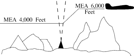
- If a MCA is specified, prior to the fix so as to cross the fix at or above the MCA. (See FIG 4-5-2.)
FIG 4-5-2 MCA Specified 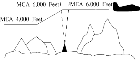
- If no MCA is specified, prior to or immediately after passing the fix where the higher MEA is designated.
(See FIG 4-5-1.)
- GNSS MEAs may be approved on published ATS routes. Air traffic may assign GNSS MEAs to GNSS-equipped aircraft
where established.
NOTE: On high altitude ATS routes, the GNSS MEA is FL180 unless published higher.
- Where MEAs have not been established, clear an aircraft at or above the minimum altitude for IFR operations prescribed by 14 CFR Section 91.177.
4-5-7. ALTITUDE INFORMATION
interpretation 11Issue altitude instructions as follows:
- Altitude to maintain or cruise. When issuing cruise in conjunction with an airport clearance limit and an unpublished route will be used, issue an appropriate crossing altitude to ensure terrain clearance until the aircraft reaches a fix, point, or route where the altitude information is available to the pilot. When issuing a cruise clearance to an airport which does not have a published instrument approach, a cruise clearance without a crossing restriction may be issued.
- PHRASEOLOGY
- MAINTAIN/CRUISE (altitude). MAINTAIN (altitude) UNTIL (time, fix, waypoint),
- or
- (number of miles or minutes) MILES/MINUTES PAST (fix, waypoint).
- CROSS (fix, point, waypoint),
- or
- INTERCEPT (route) AT OR ABOVE (altitude), CRUISE (altitude).
- NOTE:
- 1. The crossing altitude must assure IFR obstruction clearance to the point where the aircraft is established on a segment of a published route or instrument approach procedure.
- 2. When an aircraft is issued a cruise clearance to an airport which does not have a published instrument approach procedure, it is not possible to satisfy the requirement for a crossing altitude that will ensure terrain clearance until the aircraft reaches a fix, point, or route where altitude information is available to the pilot. Under those conditions, a cruise clearance without a crossing restriction authorizes a pilot to determine the minimum IFR altitude as prescribed in 14 CFR Section 91.177 and descend to it at pilot discretion if it is lower than the altitude specified in the cruise clearance.
- Instructions to climb or descend including restrictions, as required. Specify a time restriction reference the UTC clock reading with a time check. If you are relaying through an authorized communications provider, such as New York Radio or San Francisco Radio, FSS, etc., advise the radio operator to issue the current time to the aircraft when the clearance is relayed. The requirement to issue a time check must be disregarded if the clearance is issued via Controller Pilot Data Link Communications (CPDLC).
EXCEPTION. If you are in direct, two-way, VHF/UHF voice communication with the pilot and the aircraft is in radar contact, you may specify an elapsed time interval restriction, in full minute increments only, without any reference to the UTC clock. The time restriction begins once the clearance has been acknowledged by the pilot.
- EXAMPLE
- 1. “United Four Seventeen, climb to reach one three thousand at two two one five.”
“Time two two one one and one-quarter.”
The pilot is expected to be level at 13,000 feet at 2215 UTC.
- 2. Through Relay - “Speedbird Five, climb to reach flight level three-five zero at one-two-one-five, time” (Issue a time check).
- 3. In radar contact and in direct controller to pilot, two-way, VHF/UHF voice communication - “United Four Seventeen, descend to reach flight level three five zero within two minutes.” The time restriction begins once the clearance has been acknowledged by the pilot.
- 4. “United Four Seventeen climb to leave flight level three three zero within two minutes, maintain flight level three five zero.”
- REFERENCE
- FAA Order JO 7110.65, Para 1-2-1, Word Meanings.
- FAA Order JO 7110.65, Para 2-4-17, Numbers Usage.
- PHRASEOLOGY
- CLIMB/DESCEND AND MAINTAIN (altitude). If required,
- AFTER PASSING (fix, waypoint), or
- AT (time) (time in hours, minutes, and nearest quarter minute).
- CLIMB/DESCEND TO REACH (altitude) AT (time (issue time check) or fix, waypoint),
- or
- AT (time). CLIMB/DESCEND AND MAINTAIN (altitude) WHEN ESTABLISHED AT LEAST (number of miles or minutes) MILES/MINUTES PAST (fix, waypoint) ON THE (NAVAID) (specified) RADIAL.
- CLIMB/DESCEND TO REACH (altitude) AT (time or fix, waypoint),
- or
- A POINT (number of miles) MILES (direction) OF (name of DME NAVAID),
- or
- MAINTAIN (altitude) UNTIL (time (issue time check), fix, waypoint), THEN CLIMB/DESCEND AND MAINTAIN (altitude).
- Through relay:
- CLIMB TO REACH (altitude) AT (time) (issue a time check).
- Or
- Using a time interval while in radar contact and in direct controller to pilot, two-way, VHF/UHF voice communication:
- CLIMB/DESCEND TO REACH/LEAVE (altitude) WITHIN (number) MINUTES, MAINTAIN (altitude).
- Or
- CLIMB/DESCEND TO REACH/LEAVE (altitude) IN (number) MINUTES OR LESS, MAINTAIN (altitude).
- Specified altitude for crossing a specified fix or waypoint; or, specified altitude for crossing a distance (in miles) and direction from a specified fix or waypoint.
- PHRASEOLOGY
- CROSS (fix, waypoint) AT (altitude).
- CROSS (fix, waypoint) AT OR ABOVE/BELOW (altitude). CROSS (number of miles) MILES (direction) OF (name of fix, waypoint) AT (altitude).
- CROSS (number of miles) MILES (direction) OF (name of fix, waypoint) AT OR ABOVE/BELOW (altitude).
- A specified altitude over a specified fix for that portion of a descent clearance where descent at pilot's discretion is permissible. At any other time it is practicable, authorize climb/descent at pilot's discretion.
- PHRASEOLOGY
- CLIMB/DESCEND AT PILOT'S DISCRETION.
- EXAMPLE
- “United Four Seventeen, descend and maintain six thousand.”
NOTE: The pilot is expected to commence descent upon receipt of the clearance and to descend at the suggested rates specified in the AIM, para 4-4-10, Adherence to Clearance, until reaching the assigned altitude of 6,000 feet.
- EXAMPLE
- “United Four Seventeen, descend at pilot's discretion, maintain six thousand.”
NOTE: The pilot is authorized to conduct descent within the context of the term “at pilot's discretion” as described in the AIM.
- EXAMPLE
- “United Four Seventeen cross Lakeview V-O-R at or above flight level two zero zero, descend and maintain six thousand.”
NOTE: The pilot is authorized to conduct descent “at pilot's discretion” until reaching Lakeview VOR. The pilot must comply with the clearance provision to cross the Lakeview VOR at or above FL 200, and after passing Lakeview VOR, the pilot is expected to descend at the rates specified in the AIM until reaching the assigned altitude of 6,000 feet.
- EXAMPLE
- “United Four Seventeen, cross Lakeview V-O-R at and maintain six thousand.”
NOTE: The pilot is authorized to conduct descent “at pilot's discretion,” but must comply with the clearance provision to cross Lakeview VOR at 6,000 feet.
- EXAMPLE
- “United Four Seventeen, descend now to flight level two seven zero, cross Lakeview V-O-R at or below one zero thousand, descend and maintain six thousand.”
NOTE: The pilot is expected to promptly execute and complete descent to FL 270 upon receipt of the clearance. After reaching FL 270, the pilot is authorized to descend “at pilot's discretion” until reaching Lakeview VOR. The pilot must comply with the clearance provision to cross Lakeview VOR at or below 10,000 feet. After Lakeview VOR, the pilot is expected to descend at the rates specified in the AIM until reaching 6,000 feet.
- NOTE:
- 1. A descent clearance which specifies a crossing altitude authorizes descent at pilot's discretion for that portion of the flight to which the crossing altitude restriction applies.
- 2. Any other time that authorization to descend at pilot's discretion is intended, it must be specifically stated by the controller.
- 3. The pilot may need to know of any future restrictions that might affect the descent, including those that may be issued in another sector, in order to properly plan a descent at pilot's discretion.
- 4. Controllers need to be aware that the descent rates in the AIM are only suggested and aircraft will not always descend at those rates.
- REFERENCE
- P/CG, Pilot's Discretion.
- When a portion of a climb/descent may be authorized at the pilot's discretion, specify the altitude the aircraft must climb/descend to followed by the altitude to maintain at the pilot's discretion.
- PHRASEOLOGY
- CLIMB/DESCEND NOW TO (altitude), THEN CLIMB/DESCEND AT PILOT'S DISCRETION MAINTAIN (altitude).
- EXAMPLE
- “United Three Ten, descend now to flight level two eight zero, then descend at pilot's discretion maintain flight level two four zero.”
- NOTE:
- 1. The pilot is expected to commence descent upon receipt of the clearance and to descend as prescribed in the AIM, para 4-4-10, Adherence to Clearance, until FL 280. At that point, the pilot is authorized to continue descent to FL 240 within context of the term “at pilot's discretion” as described in the AIM.
- 2. Controllers need to be aware that the descent rates are only suggested and aircraft will not always descend at those rates.
- When the “pilot's discretion” portion of a climb/descent clearance is being canceled by assigning a new altitude, inform the pilot that the new altitude is an “amended altitude.”
- EXAMPLE
- “American Eighty Three, amend altitude, descend and maintain Flight Level two six zero.”
NOTE: American Eighty Three, at FL 280, has been cleared to descend at pilot's discretion to FL 240. Subsequently, the altitude assignment is changed to FL 260. Therefore, pilot's discretion is no longer authorized.
- Altitude assignments involving more than one altitude.
- PHRASEOLOGY
- MAINTAIN BLOCK (altitude) THROUGH (altitude).
- Instructions to vertically navigate SIDs/STARs with published crossing restrictions (Climb Via/Descend Via).
- When established on the SID/STAR.
- When navigating a published route inbound to the STAR.
- When cleared direct to a waypoint/fix without a published altitude, assign a crossing altitude.
- PHRASEOLOGY
- DESCEND VIA (STAR name and number).
- DESCEND VIA (STAR name and number and runway transition number)
- DESCEND VIA (STAR name and number and runway number).
- CLIMB VIA (SID name and number).
- PROCEED DIRECT (fix/waypoint), CROSS (waypoint/fix) at (altitude) THEN DESCEND VIA (STAR name and number)
- EXAMPLE
- “Descend via the Eagul Five arrival.”
- “Descend via the Wynde Eight Arrival, Runway 28 right transition.”
- “Descend via the Lendy One Arrival, Runway 22 left.”
- “Climb via the Dawgs Four Departure.”
- “Proceed direct Denis, cross Denis at or above flight level two zero zero, then descend via the Mmell One arrival.”
- NOTE: Pilots must comply with all published speed restrictions on SIDs/STARs, independent of a climb via or descend via clearance.
- Clearance to “descent via” authorizes pilots:
- 1. To descend at pilot discretion to meet published restrictions on a STAR. Pilots navigating on a STAR must maintain the last assigned altitude until receiving clearance to descend via. Once leaving an altitude, the pilot may not return to that altitude without an ATC clearance.
- 2. When cleared direct to a waypoint, to descend at pilot discretion to meet restrictions on the procedure. ATC assumes obstacle clearance responsibility for aircraft not yet established or taken off of a procedure.
- 3. To adjust speeds prior to reaching waypoints with published speed restrictions.
- NOTE: When cleared for SIDs that contain published speed restrictions, the pilot must comply with those speed restrictions independent of any “climb via” clearance. Clearance to “climb via” authorizes pilots:
- 1. When used in the IFR departure clearance, in a PDC, DCL or when subsequently cleared after departure to a waypoint depicted on a SID, to join a procedure after departure or resume a procedure.
- 2. When vertical navigation is interrupted and an altitude is assigned to maintain which is not contained on the published procedure, to climb from that previously-as- signed altitude at pilot's discretion to the altitude depicted for the next waypoint. ATC must ensure obstacle clearance until the aircraft is established on the lateral and vertical path of the SID.
- 3. Once established on the depicted departure, to climb and to meet all published or assigned altitude and speed restrictions.
- REFERENCE
- FAA Order JO 7110.65, Para 4-4-2, Route Structure Transitions.
- FAA Order JO 7110.65, Para 4-5-6, Minimum En Route Altitudes.
- FAA Order JO 7110.65, Para 5-5-9, Separation From Obstructions.
- P/CG, Climb Via, Descend Via.
NOTE: Pilots cleared for vertical navigation using the phraseology “descend via” or “climb via” must inform ATC, upon initial contact, of the altitude leaving, the runway transition or landing direction if assigned (STARs), and any assigned restrictions not published on the procedure.
- EXAMPLE
- “Delta One Twenty One leaving flight level one niner zero, descending via the Eagul Five arrival runway two-six transition.”
- “Delta One Twenty One leaving flight level one niner zero for one two thousand, descending via the Eagul Five arrival, runway two-six transition.”
- “JetBlue six zero two leaving flight level two one zero descending via the Ivane Two arrival landing south.”
- “Cactus Seven Eleven leaving two thousand climbing via the Laura Two departure.”
- “Cactus Seven Eleven leaving two thousand for one-six thousand, climbing via the Laura Two departure.”
- REFERENCE
- AIM, Para 5-2-8, Instrument Departure Procedures (DP) - Obstacle Departure Procedures (ODP) and Standard Instrument Departures (SID).
- P/CG, Top Altitude, Bottom Altitude.
- AIM, Para 5-4-1, Standard Terminal Arrival (STAR) Procedures.
- A “descend via” clearance must not be used where procedures contain only published “expect” altitude and/or speed restrictions.
NOTE: Pilots are not expected to comply with published “expect” restrictions in the event of lost communications, unless ATC has specifically advised the pilot to expect these restrictions as part of a further clearance.
- “Descend via” may be used on procedures that contain both “expect” and required altitude and speed restrictions only if altitude and/or speed restrictions or alternate restrictions are issued for the fix/waypoint associated with all expect restrictions.
- “Descend via” clearances may also be issued if an aircraft is past all fixes/waypoints that have expect restrictions.
- If it is necessary to assign a crossing altitude which differs from the STAR or SID altitude, emphasize the change to the pilot.
- PHRASEOLOGY
- DESCEND VIA (STAR name and number) ARRIVAL, EXCEPT CROSS (fix, point, waypoint), (revised altitude information).
- EXAMPLE
- “United 454 descend via the Haris One Arrival, except cross Haris at or above one six thousand.”
NOTE: The aircraft should track laterally and vertically on the Haris One Arrival and should descend so as to cross Haris at or above 16,000; remainder of the arrival must be flown as published.
- PHRASEOLOGY
- CLIMB VIA SID, EXCEPT CROSS (fix, point, waypoint), (revised altitude information).
- CLIMB VIA (SID name and number), EXCEPT CROSS (fix, point, waypoint), (revised altitude information).
- EXAMPLE
- 1. “Climb via SID except cross Mkala at or above seven thousand.”
NOTE: In Example 1, the aircraft will comply with the assigned SID departure lateral path and any published speed and altitude restrictions and climb so as to cross Mkala at or above 7,000; remainder of the departure must be flown as published.
- EXAMPLE
- 2. (There is a published altitude at Dvine WP): “Proceed direct Dvine, Climb via the Suzan Two departure except cross Mkala at or above seven thousand.”
NOTE: In Example 2, the aircraft will join the Suzan Two departure at Dvine, at the published altitude, and then comply with the published lateral path and any published speed or altitude restrictions. The aircraft will climb so as to cross Mkala at or above 7,000; remainder of the departure must be flown as published.
- When an aircraft has been issued an interim altitude and after departure ATC can subsequently clear the aircraft to climb to the original top altitude published in a SID that contains published crossing restrictions, instruct aircraft to “climb via SID.” When issuing a different altitude and compliance with published restrictions is still required, instruct aircraft to “climb via SID except maintain (altitude).”
- PHRASEOLOGY
- CLIMB VIA SID.
- CLIMB VIA SID except maintain (altitude).
- EXAMPLE
- 1. (An aircraft was issued the Teddd One departure, “climb via SID” in the IFR departure clearance. An interim altitude of 10,000 was issued instead of the published top altitude of FL 230; after departure ATC is able to issue the published top altitude): “Climb via SID.”
NOTE: In Example 1, the aircraft will track laterally and vertically on the Teddd One departure and initially climb to 10,000; Once re-issued the “climb via” clearance the interim altitude is canceled aircraft will continue climb to FL230 while complying with published restrictions.
- EXAMPLE
- 2. (Using Example 1, after departure ATC is able to issue an altitude higher than the published top altitude): “Climb via SID except maintain flight level two six zero.”
NOTE: In Example 2, the aircraft will track laterally and vertically on the Teddd One departure and initially climb to 10,000; once issued “climb via” clearance to FL260 the aircraft will continue climb while complying with published restrictions.
- If it is necessary to assign an interim altitude or assign a bottom or top altitude not contained on a STAR or SID, the provisions of subparagraph 4-5-7h may be used in conjunction with subparagraph 4-5-7a.
- PHRASEOLOGY
- DESCEND VIA THE (STAR name and number) ARRIVAL EXCEPT AFTER (fix) MAINTAIN (revised altitude information).
- EXAMPLE
- “United 454 descend via the Eagul Five Arrival, except after Geeno maintain one zero thousand.”
NOTE: The aircraft should track laterally and vertically on the Eagul Five Arrival and should descend so as to comply with all speed and altitude restrictions until reaching Geeno and then maintain 10,000. Upon reaching 10,000, aircraft should maintain 10,000 until cleared by ATC to continue to descend.
- REFERENCE
- FAA Order JO 7110.65, Para 4-7-1, Clearance Information.
- AIM, Para 5-4-1, Standard Terminal Arrival (STAR) Procedures.
- PHRASEOLOGY
- CLIMB VIA SID EXCEPT AFTER (waypoint name), MAINTAIN (altitude).
- EXAMPLE
- “Climb via SID except after Baret, maintain flight level one niner zero.”
- NOTE:
- 1. Considering the principle that the last ATC clearance issued has precedence over the previous, the phraseology “maintain (altitude)” alone cancels previously issued altitude restrictions, including SID/STAR altitude restrictions unless they are restated or modified, and authorizes an unrestricted climb or descent. Speed restrictions remain in effect unless the controller explicitly cancels the speed restrictions.
- 2. Restate “climb/descend via” and then use “except” or “except maintain” phraseology to modify published restrictions or assign a new top/bottom altitude. Use “resume” phraseology with “maintain” to rejoin a route and assign a new altitude where compliance with published altitude restrictions is not required.
- When a pilot is unable to accept a clearance, issue revised instructions to ensure positive control and approved separation.
- NOTE:
- 1. 14 CFR Section 91.123 states that a pilot is not allowed to deviate from an ATC clearance “that has been obtained...unless an amended clearance is obtained” (except when an emergency exists).
- 2. A pilot is therefore expected to advise the controller if a clearance cannot be accepted when the clearance is issued. “We will try” and other such acknowledgments do not constitute pilot acceptance of an ATC clearance.
- 3. Controllers are expected to issue ATC clearances which conform with normal aircraft operational capabilities and do not require “last minute” amendments to ensure approved separation.
- 4. “Expedite” is not to be used in lieu of appropriate restrictions to ensure separation.
4-5-8. ANTICIPATED ALTITUDE CHANGES
If practicable, inform an aircraft when to expect climb or descent clearance or to request altitude change from another facility.
- PHRASEOLOGY
- EXPECT HIGHER/LOWER IN (number of miles or minutes) MILES/MINUTES,
- or
- AT (fix). REQUEST ALTITUDE/FLIGHT LEVEL CHANGE FROM (name of facility).
- If required,
- AT (time, fix, or altitude).
4-5-9. ALTITUDE CONFIRMATION - NONRADAR
- Request a pilot to confirm assigned altitude on initial contact and when position reports are received unless:
NOTE: For the purpose of this paragraph, “initial contact” means a pilot's first radio contact with each sector/position.
- The pilot states the assigned altitude, or
- You assign a new altitude to a climbing or descending aircraft, or
- TERMINAL. The aircraft was transferred to you from another sector/position within your facility (intrafacility).
- PHRASEOLOGY
- (In level flight situations),
- VERIFY AT (altitude/flight level).
- (In climbing/descending situations),
- (if aircraft has been assigned an altitude below the lowest usable flight level),
- VERIFY ASSIGNED ALTITUDE (altitude).
- (If aircraft has been assigned a flight level at or above the lowest usable flight level),
- VERIFY ASSIGNED FLIGHT LEVEL (flight level).
- USA. Reconfirm all pilot altitude read backs.
- PHRASEOLOGY
- (If altitude read back is correct), AFFIRMATIVE (altitude).
- (If altitude read back is not correct),
- NEGATIVE. CLIMB/DESCEND AND MAINTAIN (altitude),
- or
- NEGATIVE. MAINTAIN (altitude).
Section 6. Holding Aircraft
4-6-1. CLEARANCE TO HOLDING FIX
Consider operational factors such as length of delay, holding airspace limitations, navigational aids, altitude, meteorological conditions when necessary to clear an aircraft to a fix other than the destination airport. Issue the following:
- Clearance limit (if any part of the route beyond a clearance limit differs from the last
routing cleared, issue the route the pilot can expect beyond the clearance limit).
- PHRASEOLOGY
- EXPECT FURTHER CLEARANCE VIA (routing).
- EXAMPLE
- “Expect further clearance via direct Stillwater V-O-R, Victor Two Twenty-Six Snapy intersection, direct Newark.”
- Holding instructions.
- Holding instructions may be eliminated when you inform the pilot that no delay is expected.
- When the assigned procedure or route being flown includes a charted pattern, you may omit all holding instructions except the charted holding direction and the statement “as published.” Always issue complete holding instructions when the pilot requests them.
NOTE: The most generally used holding patterns are depicted on U.S. Government or commercially produced low/high altitude en route, area, and STAR Charts.
- PHRASEOLOGY
- CLEARED TO (fix), HOLD (direction), AS PUBLISHED,
- or
- CLEARED TO (fix), NO DELAY EXPECTED.
- EFC. Do not specify this item if no delay is expected.
- When additional holding is expected at any other fix in your facility's area, state the fix and your best
estimate of the additional delay. When more than one fix is involved, state the total additional en route
delay (omit specific fixes).
NOTE: Additional delay information is not used to determine pilot action in the event of two-way communications failure. Pilots are expected to predicate their actions solely on the provisions of 14 CFR Section 91.185.
- PHRASEOLOGY
- EXPECT FURTHER CLEARANCE (time), and if required,
- ANTICIPATE ADDITIONAL (time in minutes/hours) MINUTE/HOUR DELAY AT (fix),
- or
- ANTICIPATE ADDITIONAL (time in minutes/hours) MINUTE/HOUR EN ROUTE DELAY.
- EXAMPLE
- 1. “Expect further clearance one niner two zero, anticipate additional three zero minute delay at Sweet.”
- 2. “Expect further clearance one five one zero, anticipate additional three zero minute en route delay.”
- When additional holding is expected in an approach control area, state the total additional terminal delay.
- PHRASEOLOGY
- EXPECT FURTHER CLEARANCE (time),
- and if required,
- ANTICIPATE ADDITIONAL (time in minutes/hours) MINUTE/HOUR TERMINAL DELAY.
- TERMINAL. When terminal delays exist or are expected, inform the appropriate center or approach control facility so that the information can be forwarded to arrival aircraft.
- When delay is expected, issue items in subparagraphs a and b at least 5 minutes before the aircraft is
estimated to reach the clearance limit. If the traffic situation requires holding an aircraft that is less
than 5 minutes from the holding fix, issue these items immediately.
- NOTE:
- 1. The AIM indicates that pilots should start speed reduction when 3 minutes or less from the holding fix. The additional 2 minutes contained in the 5-minute requirement are necessary to compensate for different pilot/controller ETAS at the holding fix, minor differences in clock times, and provision for sufficient planning and reaction times.
- 2. When holding is necessary, the phrase “delay indefinite” should be used when an accurate estimate of the delay time and the reason for the delay cannot immediately be determined; i.e., disabled aircraft on the runway, terminal or center sector saturation, weather below landing minimums, etc. In any event, every attempt should be made to provide the pilot with the best possible estimate of his/her delay time and the reason for the delay. Controllers/supervisors should consult, as appropriate, with personnel (other sectors, weather forecasters, the airport management, other facilities, etc.) who can best provide this information.
- PHRASEOLOGY
- DELAY INDEFINITE, (reason if known), EXPECT FURTHER CLEARANCE (time). (After determining the reason for the delay, advise the pilot as soon as possible.)
- EXAMPLE
- “Cleared to Drewe, hold west, as published, expect further clearance via direct Sidney V-O-R one three one five, anticipate additional two zero minute delay at Woody.”
- “Cleared to Aston, hold west on Victor two twenty-five, seven mile leg, left turns, expect further clearance one niner two zero, anticipate additional one five minute terminal delay.”
- “Cleared to Wayne, no delay expected.”
- “Cleared to Wally, hold north, as published, delay indefinite, snow removal in progress, expect further clearance one one three zero.”
- When additional holding is expected at any other fix in your facility's area, state the fix and your best
estimate of the additional delay. When more than one fix is involved, state the total additional en route
delay (omit specific fixes).
4-6-2. CLEARANCE BEYOND FIX
- If no delay is expected, issue a clearance beyond the clearance limit as soon as possible and, whenever possible, at least 5 minutes before the aircraft reaches the fix.
- Include the following items when issuing clearance beyond a clearance limit:
- Clearance limit or approach clearance.
- Route of flight. Specify one of the following:
- (a) Complete details of the route (airway, route, course, fix(es), azimuth course, heading, arc, or vector.)
- (b) The phrase “via last routing cleared.” Use this phrase only when the most recently issued routing to the new clearance limit is valid and verbiage will be reduced.
- PHRASEOLOGY
- VIA LAST ROUTING CLEARED.
- Assigned altitude if different from present altitude.
NOTE: Except in the event of a two-way communications failure, when a clearance beyond a fix has not been received, pilots are expected to hold as depicted on U.S. Government or commercially produced (meeting FAA requirements) low/high altitude en route and area or STAR charts. If no holding pattern is charted and holding instructions have not been issued, pilots should ask ATC for holding instructions prior to reaching the fix. If a pilot is unable to obtain holding instructions prior to reaching the fix, the pilot is expected to hold in a standard pattern on the course on which the aircraft approached the fix and request further clearance as soon as possible.
4-6-3. DELAYS
- Advise your supervisor or flow controller as soon as possible when you delay or expect to delay aircraft.
- When arrival delays reach or are anticipated to reach 30 minutes, take the following action:
- EN ROUTE. The center responsible for transferring control to an approach control facility or, for a nonapproach control destination, the center in whose area the aircraft will land must issue total delay information as soon as possible after the aircraft enters the center's area. Whenever possible, the delay information must be issued by the first center controller to communicate with the aircraft.
- TERMINAL. When tower en route control service is being provided, the approach control facility whose area contains the destination airport must issue total delay information as soon as possible after the aircraft enters its approach control area. Whenever possible, the delay information must be issued by the first terminal controller to communicate with the aircraft.
- Unless a pilot requests delay information, the actions specified in subparas 1 and 2 above may be omitted
when total delay information is available to pilots via ATIS.
- PHRASEOLOGY
- (Airport) ARRIVAL DELAYS (time in minutes/hours).
4-6-4. HOLDING INSTRUCTIONS
When issuing holding instructions, specify:
- Direction of holding from the fix/waypoint.
- Holding fix or waypoint.
NOTE: The holding fix may be omitted if included at the beginning of the transmission as the clearance limit.
- Radial, course, bearing, track, azimuth, airway, or route on which the aircraft is to hold.
- Leg length in miles if DME or RNAV is to be used. Specify leg length in minutes if the pilot requests it or you consider it necessary.
- Direction of holding pattern turns only if left turns are to be made, the pilot requests it, or you consider it necessary.
- PHRASEOLOGY
- HOLD (direction) OF (fix/waypoint) ON (specified radial, course, bearing, track, airway, azimuth(s), or route.)
- If leg length is specified,
- (number of minutes/miles) MINUTE/MILE LEG.
- If direction of turn is specified, LEFT/RIGHT TURNS.
- Issue maximum holding airspeed advisories when an aircraft is:
- Approved to exceed the maximum airspeed of a pattern, and is cleared into a holding pattern that will protect for the greater speed; or
- Observed deviating from the holding pattern airspace area; or
- Cleared into an airspeed restricted holding pattern in which the icon has not been published.
- EXAMPLE
- Due to turbulence, a turboprop requests to exceed the recommended maximum holding airspeed. ATCS may clear the aircraft into a pattern that protects for the airspeed request, and must advise the pilot of the maximum holding airspeed for the holding pattern airspace area.
- PHRASEOLOGY
- “MAXIMUM HOLDING AIRSPEED IS TWO ONE ZERO KNOTS.”
4-6-5. VISUAL HOLDING POINTS
You may use as a holding fix a location which the pilot can determine by visual reference to the surface if he/she is familiar with it.
- PHRASEOLOGY
- HOLD AT (location) UNTIL (time or other condition.)
4-6-6. HOLDING FLIGHT PATH DEVIATION
Approve a pilot's request to deviate from the prescribed holding flight path if obstacles and traffic conditions permit.
4-6-7. UNMONITORED NAVAIDs
Separate an aircraft holding at an unmonitored NAVAID from any other aircraft occupying the course which the holding aircraft will follow if it does not receive signals from the NAVAID.
4-6-8. ILS PROTECTION/CRITICAL AREAS
When the official weather observation indicates a ceiling of less than 800 feet or visibility of 2 miles, do not authorize aircraft to hold below 5,000 feet AGL inbound toward the airport on or within 1 statute mile of the localizer between the ILS OM or the fix used in lieu of the OM and the airport. USAF. The holding restriction applies only when an arriving aircraft is between the ILS OM or the fix used in lieu of the OM and the runway.
- REFERENCE
- FAA Order 8260.3, United States Standard for Terminal Instrument Procedures (TERPS), Chapter 17, Basic Holding Criteria.
Section 7. Arrival Procedures
4-7-1. CLEARANCE INFORMATION
Clear an arriving aircraft to a clearance limit by specifying the following:
-
Name of fix or airport.
- PHRASEOLOGY
- CLEARED TO (destination) AIRPORT.
- Or
- CLEARED TO (NAVAID name and type if known).
- Or
- CLEARED TO (intersection or waypoint name and type if known).
-
Route of flight including a STAR/RNAV STAR/FMSP and STAR/RNAV STAR/FMSP transition, if appropriate. Assign a
STAR/RNAV STAR/FMSP and STAR/RNAV STAR/FMSP transition to any aircraft in lieu of other routes; e.g., airways or
preferential arrival routes when the routings are the same. The clearance must include the name and transition, if
necessary, of the STAR/RNAV STAR/FMSP to be flown.
TERMINAL: When the STAR/RNAV STAR/FMSP transition is designed to provide course guidance to multiple runways, the facility must state intended runway number on initial contact, or as soon as practical. If the runway assignment, or any subsequent runway change, is not issued prior to 10 NM from the runway transition waypoint, radar vectors to final must be provided.
- PHRASEOLOGY
- (STAR/RNAV STAR/FMSP name and number) ARRIVAL.
- (STAR/RNAV STAR/FMSP name and number) ARRIVAL, (transition name) TRANSITION.
- CHANGE/AMEND TRANSITION TO (runway number).
- CHANGE/AMEND TRANSITION TO (runway number) TURN LEFT/RIGHT or HEADING (heading) FOR VECTOR TO FINAL APPROACH COURSE.
- EXAMPLE
- “Rosewood One arrival.”
- “Rosewood One arrival, Delta transition.”
- “Change transition to Runway 09 right.”
- “Amend transition to Runway 22 left, turn right heading 180 for vector to final approach course.”
- NOTE:
- 1. If a civil pilot does not wish to use a STAR issued in an ATC clearance or any other STAR published for that location, the pilot is expected to advise ATC.
- 2. Arrival procedure descriptive text contained within parentheses (for example, “Devine One (RNAV) Arrival”) are not included in arrival clearance phraseology.
-
Altitude instructions, as follows:
- Assigned altitude; or
- Instructions to vertically navigate on the STAR/FMSP or STAR/FMSP transition.
- EXAMPLE
- “Bayview Three Arrival, Helen Transition, maintain Flight Level Three Three Zero.”
- “Descend via the Civit One Arrival.”
- “Descend via the Lendy One Arrival, Runway 22 left.”
- “Cross JCT at Flight Level Two Four Zero.”
- “Descend via the Coast Two Arrival.”
- “Civit One Arrival, Descend and Maintain Flight Level Two Four Zero.”
- Issue holding instructions, EFC, and additional delay information as required.
- Instructions regarding further communications as appropriate.
4-7-2. ADVANCE DESCENT CLEARANCE
EN ROUTE
Take the following action when exercising control of aircraft landing at an airport located in an adjacent center's control area near the common boundary:
- Coordinate with the receiving facility for a lower altitude and issue a clearance to the aircraft as appropriate.
- Initiate this action at a distance sufficient from destination to allow for normal descent and speed reduction.
4-7-3. SINGLE FREQUENCY APPROACHES (SFA)
TERMINAL
Where SFA procedures for military single-piloted turbojet aircraft on an IFR flight plan are contained in a letter of agreement, do not require a radio frequency change after the aircraft begins approach or after initial contact during an en route descent until a landing or low approach has been completed except under the following conditions:
- REFERENCE
- FAA Order JO 7610.4, Special Operations, Para 9-3-6, Single Frequency Approach (SFA).
- P/CG Term - Single-Piloted Aircraft.
- During daylight hours while the aircraft is in VFR conditions.
- On pilot request.
- When pilot cancels IFR flight plan.
- In an emergency situation.
- When aircraft is cleared for visual approach.
4-7-4. RADIO FREQUENCY AND RADAR BEACON CHANGES FOR MILITARY AIRCRAFT
When military single-piloted turbojet aircraft will conduct an approach wholly or partly in IFR conditions or at night, take the following action:
NOTE: It is known that the mental distraction and the inadvertent movement of aircraft controls resulting from the pilot's turning, reaching, or leaning to change frequencies can induce spatial disorientation (vertigo).
-
Avoid radio frequency and radar beacon changes to the maximum extent that communications capabilities and traffic
will permit. However, when changes are required:
- Give instructions early enough to allow the change before the aircraft reaches the approach fix or handoff point.
- Keep frequency/radar beacon changes to a minimum below 2,500 feet above the surface.
- Avoid requiring frequency/radar beacon changes during the time the aircraft is making a turn.
-
When traffic volume requires, a frequency other than the one used by aircraft making approaches may be assigned
for use in transferring control to the approach control facility.
TERMINAL
- If practicable, use a frequency common to both the GCA unit and approach control to minimize frequency changes.
- When a GCA unit is not able to communicate on a common frequency, a change to a GCA frequency may be authorized.
-
When a nonradar approach will be made, aircraft may be instructed to change to tower frequency when:
- The reported ceiling is at or above 1,500 feet and visibility is 5 statute miles or more.
- The aircraft reports able to proceed by visual reference to the surface.
- The aircraft requests and is cleared for a contact approach.
- The aircraft is cleared for a visual approach. f. Avoid making frequency/radar beacon changes after an aircraft begins a high altitude approach.
- In the event of a missed approach, do not require a frequency/radar beacon change before the aircraft reaches the missed approach altitude, the MEA, or the MVA.
4-7-5. MILITARY TURBO JET ENROUTE DESCENT
Provide military turbojet aircraft the same arrival procedures that are provided for nonmilitary turbojet aircraft except:
NOTE: It is the responsibility of the pilot to request a high altitude approach if he/she does not want normal arrival handling.
- An en route descent may be used in a nonradar environment; however, radar capability should exist which will permit the aircraft to be vectored to the final approach course of a published high altitude instrument approach procedure or PAR/ASR approach. Do not use this procedure if other than normal vectoring delays are anticipated.
- Prior to issuance of a descent clearance below the highest initial approach fix altitude established for any high altitude instrument approach procedure for the destination airport inform the aircraft:
- Type of approach to expect.
- EXAMPLE
- “Expect V-O-R approach to runway three two.”
- Radar vectors will be provided to the final approach course.
- EXAMPLE
- “Expect surveillance/precision approach to runway one seven; radar vectors to final approach course.”
- Current weather whenever the ceiling is below 1,000 feet (USAF: 1,500 feet) or the highest circling minimum whichever is greater, or when the visibility is less than 3 miles.
- EXAMPLE
- “Expect ILS approach to runway eight; radar vectors to localizer course. Weather (reported weather).”
- Type of approach to expect.
- If ATIS is provided and the pilot advises he/she has received the current ATIS broadcast before the descent clearance in subpara b is issued, omit those items in subpara b that are contained in the broadcast.
- To avoid requiring an aircraft to fly at low altitudes for an excessive distance, descent clearance should be issued at a point determined by adding 10 to the first two digits of the flight level.
- EXAMPLE
- For FL 370, 37 + 10 = 47 miles.
NOTE: Turbojet en route descents are based on a rate of descent of 4,000 to 6,000 feet per minute.
- Do not terminate the en route descent of an aircraft without the consent of the pilot except as required by radar outage or an emergency situation.
4-7-6. ARRIVAL INFORMATION
EN ROUTE
- Forward the following information to nonapproach control towers soon enough to permit adjustment of the traffic flow or to FSSs (Alaska Only) soon enough to provide local airport advisory where applicable:
- Aircraft identification.
- Type of aircraft.
- ETA.
- Type of instrument approach procedure the aircraft will execute; or
- For SVFR, the direction from which the aircraft will enter Class B, Class C, Class D, or Class E surface area and any altitude restrictions that were issued; or
- For aircraft executing a contact approach the position of the aircraft.
NOTE: Specific time requirements are usually stated in a letter of agreement.
- Forward the following information to approach control facilities before transfer of control jurisdiction:
NOTE: Transfer points are usually specified in a letter of agreement.
- Aircraft identification.
- Type of aircraft and appropriate aircraft equipment suffix.
- ETA or actual time, and proposed or actual altitude over clearance limit. The ETA need not be given if the arrival information is being forwarded during a radar handoff.
- Clearance limit (when other than the destination airport) and EFC issued to the aircraft. Clearance limit may be omitted when provided for in a letter of agreement.
- Time, fix, or altitude when control responsibility is transferred to the approach control facility. This information may be omitted when provided for in a letter of agreement.
- PHRASEOLOGY
- (Identification), (type of aircraft), ESTIMATED/OVER (clearance limit), (time), (altitude), EFC (time).
- If required, YOUR CONTROL,
- or
- YOUR CONTROL AT (time, fix or altitude).
4-7-7. WEATHER INFORMATION
EN ROUTE
When an available official weather report indicates weather conditions are below a 1,000-foot (USAF: 1,500-foot) ceiling or below the highest circling minimum, whichever is higher, or less than three-miles visibility for the airport concerned, transmit the weather report and changes classified as special weather observations to an arriving aircraft prior to or as part of the approach clearance when:
- It is transmitted directly to the pilot via center controller-to-pilot communications.
- It is relayed through a communications station other than an air carrier company radio or through a nonapproach control facility. You may do this by telling the station or nonapproach control facility to issue current weather.
4-7-8. BELOW MINIMA REPORT BY PILOT
If an arriving aircraft reports weather conditions are below his/her landing minima:
NOTE: Determination that existing weather/visibility is adequate for approach/landing is the responsibility of the pilot/aircraft operator.
- Issue appropriate instructions to the aircraft to hold or proceed to another airport.
- Adjust, as necessary, the position in the landing sequence of any other aircraft desiring to make approaches and issue approach clearances accordingly.
4-7-9. TRANSFER OF JURISDICTION
Transfer radio communications and control responsibility early enough to allow the receiving facility to clear an aircraft beyond the clearance limit before the aircraft reaches it.
4-7-10. APPROACH INFORMATION
interpretation 7-
Both en route and terminal approach control sectors must provide current approach information to aircraft destined
to airports for which they provide approach control services. This information must be provided on initial contact
or as soon as possible thereafter. Approach information contained in the ATIS broadcast may be omitted if the
pilot states the appropriate ATIS code. For pilots destined to an airport without ATIS, items 3-5 below may be
omitted after the pilot advises receipt of the automated weather; otherwise, issue approach information by
including the following:
- Approach clearance or type approach to be expected if two or more approaches are published and the clearance limit does not indicate which will be used.
- Runway if different from that to which the instrument approach is made.
- Surface wind.
- Ceiling and visibility if the reported ceiling at the airport of intended landing is below 1,000 feet or below the highest circling minimum, whichever is greater, or the visibility is less than 3 miles.
- Altimeter setting for the airport of intended landing.
-
Upon pilot request, controllers must inform pilots of the frequency where automated weather data may be obtained
and, if appropriate, that airport weather is not available.
- PHRASEOLOGY
- (Airport) AWOS/ASOS WEATHER AVAILABLE ON (frequency).
- ASOS/AWOS must be set to provide one minute weather at uncontrolled airports that are without ground-to-air weather broadcast capability by a CWO, NWS or FSS observer.
- Controllers will consider the long-line disseminated weather from an automated weather system at an uncontrolled airport as trend information only and must rely on the pilot for the current weather information for that airport.
- Controllers must issue the last long-line disseminated weather to the pilot if the pilot is unable to receive the ASOS/AWOS broadcast.
NOTE: Aircraft destined to uncontrolled airports, which have automated weather data with broadcast capability, should monitor the ASOS/AWOS frequency to ascertain the current weather at the airport. The pilot should advise the controller when he/she has received the broadcast weather and state his/her intentions.
- Issue any known changes classified as special weather observations as soon as possible. Special weather observations need not be issued after they are included in the ATIS broadcast and the pilot states the appropriate ATIS code.
-
Advise pilots when the ILS on the runway in use is not operational if that ILS is on the same frequency as an
operational ILS serving another runway.
- EXAMPLE
- “Expect visual approach runway two five right, runway two five right I-L-S not operational.”
- TERMINAL: If multiple runway transitions are depicted on a STAR procedure, advise pilots of the runway assignment on initial contact or as soon as possible thereafter.
4-7-11. ARRIVAL INFORMATION BY APPROACH CONTROL FACILITIES
- Forward the following information to nonapproach control towers soon enough to permit adjustment of the traffic flow or to FSSs soon enough to provide local airport advisory where applicable:
- Aircraft identification.
- Type of aircraft.
- ETA.
- Type of instrument approach procedure the aircraft will execute; or
- For SVFR, the direction from which the aircraft will enter Class B, Class C, Class D, or Class E surface area and any altitude restrictions that were issued; or
- For aircraft executing a contact approach, the position of the aircraft.
NOTE: Specific time requirements are usually stated in a letter of agreement.
- Forward the following information to the tower when the tower and TRACON are part of the same facility:
- Aircraft identification.
- Type aircraft if required for separation purposes.
- Type of instrument approach procedure and/or runway if differing from that in use.
NOTE: The local controller has the responsibility to determine whether or not conditions are adequate for the use of STARS data on the CTRD where a facility directive authorizes its use for the transfer of arrival data.
- REFERENCE
- FAA Order JO 7210.3, Para 12-2-4, Use of Modify and Quick Look Functions.
- FAA Order JO 7210.3, Para 12-8-4, Use of STARS Quick Look Functions.
- Where the collocated or satellite tower has STARS data displayed on its CTRD, the STARS modify or quick look functions may be used to forward arrival data provided that a facility directive at the collocated tower or a letter of agreement with the satellite tower exists which outlines procedures for using STARS for transferring this data.
- Forward the following information to centers:
- Where two or more instrument approach procedures are published for the airport, the particular procedure which an aircraft can expect or that it will be vectored toward the airport for a visual approach.
- Highest altitude being used by the approach control facility at the holding fix.
- Average time interval between successive approaches.
- Arrival time of aircraft over the holding fix or, if control has been transferred to you before an aircraft has reached the fix, a statement or other indication acknowledging receipt of control responsibility.
- Revised EFC if different by 10 minutes or more from that issued by the center.
- Missed approaches if they affect center operations.
- Information relating to an unreported or overdue aircraft.
4-7-12. AIRPORT CONDITIONS
- EN ROUTE. Before issuing an approach clearance, and subsequently as changes occur, inform an aircraft of any abnormal operation of approach and landing aids and of destination airport conditions that you know of which might restrict an approach or landing. This information may be omitted if it is contained in the ATIS broadcast and the pilot states that he/she has received the appropriate ATIS code.
- NOTE:
- 1. Airport conditions information, in the provision of en route approach control service, does not include the following:
- a. The airport surface environment other than the landing area(s) (e.g. TAXIWAY, APRON or SERVICE keyword NOTAMs).
- b. Obstruction information (e.g. OBST NOTAMs) for aircraft that will be cleared for an instrument approach.
- c. Information pertaining to cold temperature compensation.
- 2. When advised of special use airspace (SUA) or military training route (MTR) activation, appropriate action is taken to separate nonparticipating IFR aircraft from those activities when required, and/or to issue applicable advisories as warranted. When meeting this requirement, there is no requirement for controllers to additionally issue the associated D NOTAM activating that SUA or MTR to the pilot. Accordingly, D NOTAMs for SUA that contain the accountability codes SUAE, SUAC, and SUAW are not required to be issued.
- 3. Although a pilot may have obtained NOTAM information during pre-flight briefings, airport conditions may have changed in flight. Therefore a pilot stating, or a controller asking, if they “have the NOTAMS” does not relieve the controller of the responsibility of issuing airport conditions that might restrict an approach or landing. Additionally, controller instructions to contact FSS to obtain the NOTAMs does not relieve the controller of their responsibilities specified in this paragraph.
- TERMINAL. On first contact or as soon as possible thereafter, and subsequently as changes occur, inform an aircraft of any abnormal operation of approach and landing aids and of destination airport conditions that you know of which might restrict an approach or landing. This information may be omitted if it is contained in the ATIS broadcast and the pilot states the appropriate ATIS code.
- Issue RwyCC contained in a FICON NOTAM to aircraft in accordance with one of the following:
- Before or when an approach clearance is issued.
- Before an en route descent clearance is issued.
- TERMINAL. Prior to departure.
- As soon as possible after receipt of any subsequent changes in previously issued RwyCC information.
- RwyCC may be issued in lieu of the complete FICON NOTAM. Issue the complete FICON NOTAM upon pilot request, workload permitting.
- EXAMPLE
- Boston Runway Two Seven, field condition, three, three, three, one hundred percent, two inches dry snow over compacted snow. Observed at one five three zero zulu.
NOTE: RwyCC may be transmitted via the ATIS as prescribed in Paragraphs 2-9-3, Content; 3-3-1, Landing Area Condition; 3-9-1, Departure Information; and 3-10-1, Landing Information.
- TERMINAL. Where RCRs are provided, transmit this information to USAF and ANG aircraft. Issue the RCR to other aircraft upon pilot request.
NOTE: USAF offices furnish RCR information at airports serving USAF and ANG aircraft.
Section 8. Approach Clearance Procedures
4-8-1. APPROACH CLEARANCE
interpretation 15 interpretation 16- Clear aircraft for “standard” or “special” instrument approach procedures only.
- To require an aircraft to execute a particular instrument approach procedure, specify in the approach clearance the name of the approach as published on the approach chart. Where more than one procedure is published on a single chart and a specific procedure is to be flown, amend the approach clearance to specify execution of the specific approach to be flown. If only one instrument approach of a particular type is published, the approach needs not be identified by the runway reference.
- An aircraft conducting an ILS or LDA approach must be advised at the time an approach clearance is issued when the glideslope is reported out of service, unless the title of the published approach procedure allows (for example, ILS or LOC Rwy 05).
- Standard instrument approach procedures (SIAP) must begin at an initial approach fix (IAF) or an intermediate fix (IF) if there is not an IAF.
- Where adequate radar coverage exists, radar facilities may vector aircraft to the final approach course in accordance with Paragraph 5-9-1, Vectors to Final Approach Course, and Paragraph 5-9-2, Final Approach Course Interception.
- Where adequate radar coverage exists, radar facilities may clear an aircraft to any fix 3 NM or more prior to the FAF, along the final approach course, at an intercept angle not greater than 30 degrees.
- Controllers must not disapprove a pilot request to cold temperature compensate in conjunction with the issuance of an approach clearance.
- PHRASEOLOGY
- CLEARED (type) APPROACH.
- CLEARED APPROACH.
- (To authorize a pilot to execute his/her choice of instrument approach),
- CLEARED (specific procedure to be flown) APPROACH.
- (Where more than one procedure is published on a single chart and a specific procedure is to be flown),
- CLEARED (ILS/LDA) APPROACH, GLIDESLOPE UNUSABLE.
- (To authorize a pilot to execute an ILS or an LDA approach when the glideslope is out of service)
- CLEARED LOCALIZER APPROACH
- (When the title of the approach procedure contains “or LOC”)
- CANCEL APPROACH CLEARANCE (additional instructions as necessary)
- (When it is necessary to cancel a previously issued approach clearance)
- EXAMPLE
- “Cleared Approach.”
- “Cleared (V-O-R/I-L-S/Localizer) Approach.”
- “Cleared L-D-A Runway Three-Six Approach.”
- “Cleared Localizer Back Course Runway One-Three Approach.”
- “Cleared (GPS/RNAV Z) Runway Two-Two Approach.”
- “Cleared BRANCH ONE Arrival and (ILS/RNAV) Runway One-Three Approach.”
- “Cleared I-L-S Runway Three-Six Approach, glideslope unusable.”
- “Cleared S-D-F Approach.”
- “Cleared G-L-S Approach.”
- NOTE:
- 1. Clearances authorizing instrument approaches are issued on the basis that, if visual contact with the ground is made before the approach is completed, the entire approach procedure will be followed unless the pilot receives approval for a contact approach, is cleared for a visual approach, or cancels their IFR flight plan.
- 2. Approach clearances are issued based on known traffic. The receipt of an approach clearance does not relieve the pilot of his/her responsibility to comply with applicable Parts of Title 14 of the Code of Federal Regulations and the notations on instrument approach charts which levy on the pilot the responsibility to comply with or act on an instruction; for example, “Straight-in minima not authorized at night,” “Procedure not authorized when glideslope/glidepath not used,” “Use of procedure limited to aircraft authorized to use airport,” or “Procedure not authorized at night” or Snowflake icon with associated temperature.
- 3. In some cases, the name of the approach, as published, is used to identify the approach, even though a component of the approach aid, other than the localizer on an ILS is inoperative.
- 4. Where more than one procedure to the same runway is published on a single chart, each must adhere to all final approach guidance contained on that chart, even though each procedure will be treated as a separate entity when authorized by ATC.
- 5. The use of alphabetical identifiers in the approach name with a letter from the end of the alphabet; for example, X, Y, Z, such as “HI TACAN Z Rwy 6L or RNAV(GPS) Y Rwy 04”, denotes multiple straight-in approaches to the same runway that use the same approach aid.
- 6. Alphabetical suffixes with a letter from the beginning of the alphabet; for example, A, B, C, denote a procedure that does not meet the criteria for straight-in landing minimums authorization.
- 7. 14 CFR Section 91.175(j) requires a pilot to receive a clearance to conduct a procedure turn when vectored to a final approach course or fix, conducting a timed approach, or when the procedure specifies “NO PT.”
- 8. An aircraft which has been cleared to a holding fix and prior to reaching that fix is issued a clearance for an approach, but not issued a revised routing; that is, “proceed direct to....” may be expected to proceed via the last assigned route, a feeder route (if one is published on the approach chart), and then to commence the approach as published. If, by following the route of flight to the holding fix, the aircraft would overfly an IAF or the fix associated\ with the beginning of a feeder route to be used, the aircraft is expected to commence the approach using the published feeder route to the IAF or from the IAF as appropriate; that is, the aircraft would not be expected to overfly and return to the IAF or feeder route.
- 9. Approach name items contained with in parenthesis; for example, RNAV (GPS) Rwy 04, are not included in approach clearance phraseology.
- 10. Pilots are required to advise ATC when intending to apply cold temperature compensation to instrument
approach segments. Pilots must advise ATC of the amount of compensation required for each affected segment on
initial contact or as soon as possible. Pilots are not required to advise ATC when correcting on the final
segment only. Controllers may delay the issuance of an approach clearance to comply with approved separation
requirements when informed that a pilot will apply cold temperature compensation (CTC). Pilots will not apply
altitude compensation, unless authorized, when assigned an altitude prior to an approach clearance.
Consideration should be given to vectoring aircraft at or above the requested compensating altitude if
possible. This eliminates pilots having to climb once on the approach.
- REFERENCE
- FAA Order 8260.3, United States Standard for Terminal Instrument Procedures (TERPS).
- P/CG Term - Cold Temperature Compensation
- AIM, Paragraph 5-1-17, Cold Temperature Operations.
- AIM, Paragraph 5-5-4, Instrument Approach.
- 11. There are some systems, for example, Enhanced Flight Vision System (EFVS), which allow aircraft to
descend below published final approach minimums.
- REFERENCE
- 14 CFR § 91.175(l)
- P/CG Term - Enhanced Flight Vision System (EFVS)
- For aircraft operating on unpublished routes, issue the approach clearance only after the aircraft is:
- Established on a segment of a published route or instrument approach procedure, or (See FIG 4-8-1)
- EXAMPLE
- The aircraft is established on a segment of a published route at 5,000 feet.
- “Cleared V-O-R Runway Three Four Approach.”
FIG 4-8-1 Approach Clearance Example 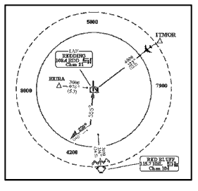
- Assigned an altitude to maintain until the aircraft is established on a segment of a published route or
instrument approach procedure. (See FIG 4-8-2.)
- EXAMPLE
- Aircraft 1 is cleared direct LEFTT. The MVA in the area is 3,000 feet, and the aircraft is at 4,000 feet. “Cross LEFTT at or above three thousand five hundred, cleared RNAV Runway One Eight Approach.” The MVA in the area is 3,000 feet and Aircraft 2 is at 3,000 feet. “Cleared direct LEFTT direct CENTR, maintain three thousand until CENTR, cleared straight-in RNAV Runway One Eight Approach.”
FIG 4-8-2 Approach Clearance Example 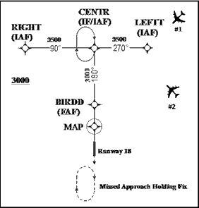
- NOTE:
- 1. The altitude assigned must assure IFR obstruction clearance from the point at which the approach clearance is issued until established on a segment of a published route or instrument approach procedure.
- 2. If the altitude assignment is VFR-on-top, it is conceivable that the pilot may elect to remain high until arrival over the final approach fix which may require the pilot to circle to descend so as to cross the final approach fix at an altitude that would permit landing.
- 3. An aircraft is not established on an approach until at or above an altitude published on that segment of the approach.
- REFERENCE
- FAA Order 8260.3 United States Standard for Terminal Instrument Procedures (TERPS), Para 11-3
- Established on a segment of a published route or instrument approach procedure, or (See FIG 4-8-1)
- Except for visual approaches, do not clear an aircraft direct to the FAF unless it is also an IAF, wherein the aircraft is expected to execute the depicted procedure turn or hold-in-lieu of procedure turn.
- Intercept angles greater than 90 degrees maybe used when a procedure turn, a hold-in-lieu of procedure turn pattern, or arrival holding is depicted and the pilot will execute the procedure.
- If a procedure turn, hold-in-lieu of procedure turn, or arrival holding pattern is depicted and the angle of
intercept is 90 degrees or less, the aircraft must be instructed to conduct a straight-in approach if ATC does not
want the pilot to execute a procedure turn or hold-in-lieu of procedure turn. (See FIG 4-8-3)
- PHRASEOLOGY
- CLEARED STRAIGHT-IN (type) APPROACH
- NOTE:
- 1. Restate “cleared straight-in” in the approach clearance even if the pilot was advised earlier to expect a straight-in approach.
- 2. Some approach charts have an arrival holding pattern depicted at the IAF using a “thin line” holding symbol. It is charted where holding is frequently required prior to starting the approach procedure so that detailed holding instructions are not required. The arrival holding pattern is not authorized unless assigned by ATC.
- EXAMPLE
- “Cleared direct SECND, maintain at or above three thousand until SECND, cleared straight-in ILS Runway One-Eight approach.”
- REFERENCE
- AIM, Paragraph 5-4-5, Instrument Approach Procedure Charts.
- AIM, Paragraph 5-4-9, Procedure Turn and Hold-in-lieu of Procedure Turn.
FIG 4-8-3 Approach Clearance Example For Aircraft On a Conventional Approach 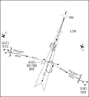
- EXAMPLE
- Aircraft 1 can be cleared direct to XYZ VORTAC, or SECND because the intercept angle is 90 degrees or less.
- Aircraft 2 cannot be cleared to XYZ VORTAC because the intercept angle is greater than 90 degrees.
- Aircraft 2 can be cleared to SECND if allowed to execute the hold-in-lieu of procedure turn pattern.
- Except when applying radar procedures, timed or visual approaches, clear an aircraft for an approach to an airport when the preceding aircraft has landed or canceled IFR flight plan.
- Where instrument approaches require radar monitoring and radar services are not available, do not use the
phraseology “cleared approach,” which allows the pilot his/her choice of instrument approaches.
RNAV APPLICATION
- For RNAV-equipped aircraft operating on unpublished routes, issue approach clearance for conventional or RNAV
SIAP including approaches with RF legs only after the aircraft is: (See FIG 4-8-4).
- Established on a heading or course direct to the IAF at an intercept angle not greater than 90 degrees and
is assigned an altitude in accordance with b2. Radar monitoring is required to the IAF for RNAV (RNP)
approaches when no hold-in-lieu of procedure turn is executed.
- EXAMPLE
- Aircraft 1 can be cleared direct to CENTR. The intercept angle at that IAF is 90 degrees or less. The minimum altitude for IFR operations (14 CFR, section 91.177) along the flight path to the IAF is 3,000 feet. If a hold in lieu of procedure turn pattern is depicted at an IAF and a TAA is not defined, the aircraft must be instructed to conduct a straight-in approach if ATC does not want the pilot to execute a hold-in-lieu procedure turn. “Cleared direct CENTR, maintain at or above three thousand until CENTR, cleared straight-in RNAV Runway One-Eight Approach.”
- Established on a heading or course direct to the IF at an angle not greater than 90 degrees, provided the
following conditions are met:
- (a) Assign an altitude in accordance with b2 that will permit a normal descent to the FAF.
NOTE: Controllers should expect aircraft to descend at approximately 150-300 feet per nautical mile when applying guidance in subparagraph h2(a).
- (b) Radar monitoring is provided to the IF.
- (c) The SIAP must identify the intermediate fix with the letters “IF.”
- (d) For procedures where an IAF is published, the pilot is advised to expect clearance to the IF at
least 5 miles from the fix.
- EXAMPLE
- “Expect direct CENTR for RNAV Runway One-Eight Approach.”
- (a) Assign an altitude in accordance with b2 that will permit a normal descent to the FAF.
- Established on a heading or course direct to a fix between the IF and FAF, at an intercept angle not greater
than 30 degrees, and assigned an altitude in accordance with b2.
- EXAMPLE
- Aircraft 1 is more than 5 miles from SHANN. The minimum altitude for IFR operations (14 CFR Section 91.177) along the flight path to SHANN is 3,000 feet. SHANN is a step down fix between the IF/IAF (CENTR) and the FAF. To clear Aircraft 1 to SHANN, ATC must ensure the intercept angle for the intermediate segment at SHANN is not greater than 30 degrees and must be cleared to an altitude that will allow a normal descent to the FAF. “Cleared direct SHANN, cross SHANN at or above three thousand, cleared RNAV Runway One-Eight Approach.”
FIG 4-8-4 Approach Clearance Example For RNAV Aircraft 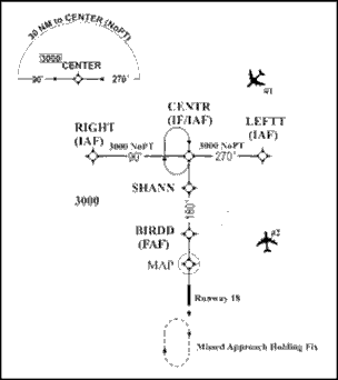
- EXAMPLE
- Aircraft 2 cannot be cleared direct to CENTR unless the aircraft is allowed to execute the hold-in-lieu of procedure turn. The intercept angle at that IF/IAF is greater than 90 degrees. The minimum altitude for IFR operations (14 CFR Section 91.177) along the flight path to the IAF is 3,000 feet. “Cleared direct CENTR, maintain at or above three thousand until CENTR, cleared RNAV Runway One-Eight approach.” The pilot is expected to proceed direct CENTR and execute the hold-in-lieu of procedure turn.
- Aircraft 2 can be cleared direct LEFTT. The intercept angle at that IAF is 90 degrees or less. The minimum altitude for IFR operations (14 CFR Section 91.177) along the flight path to the IAF is 3,000 feet. “Cleared direct LEFTT, maintain at or above three thousand until LEFTT, cleared RNAV Runway One-Eight Approach.” The pilot does not have to be cleared for a straight-in approach since no hold-in-lieu of procedure turn pattern is depicted at LEFTT.
- Established on a heading or course direct to the IAF at an intercept angle not greater than 90 degrees and
is assigned an altitude in accordance with b2. Radar monitoring is required to the IAF for RNAV (RNP)
approaches when no hold-in-lieu of procedure turn is executed.
- Clear RNAV-equipped aircraft conducting RNAV instrument approach procedures that contain radius to fix (RF)
legs:
- Via published transitions, or
- In accordance with paragraph h.
- Do not clear aircraft direct to any waypoint beginning or within an RF leg.
- Do not assign fix/waypoint crossing speeds in excess of charted speed restrictions.
- NOTE:
- 1. RNAV approaches (containing RF legs) that commence at 10,000 feet or above require special procedures that will be site specific and specified in a facility directive.
- 2. An RF leg is defined as a curved segment indicating a constant radius circular path about a defined turn center that begins at a waypoint. RF legs may have maximum airspeeds charted for procedural containment that must be followed.
- 3. If an aircraft is vectored off the procedure, expect the aircraft to request a return to an IAF.
FIG 4-8-5 Radius to Fix (RF) and Track to Fix (TF) 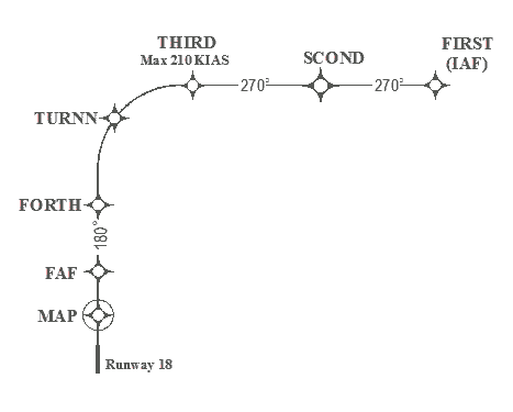
- NOTE:
- 1. The segment between THIRD and FORTH in FIG 4-8-5 is an RF leg.
- 2. The straight segments between waypoints in FIG 4-8-5 are TF legs.
- Where a terminal arrival area (TAA) has been established to support RNAV approaches, use the procedures under
subparagraph b above. (See FIG 4-8-6.)
- NOTE:
- 1. Aircraft that are within the lateral boundary of a TAA, and at or above the TAA minimum altitude, are established on the approach and may be issued an approach clearance without an altitude restriction.
- 2. The TAA minimum altitude may be higher than the MVA/MIA. If an aircraft is below the TAA minimum altitude, it must either be assigned an altitude to maintain until established on a segment of a published route or instrument approach procedure, or climbed to the TAA altitude.
- EXAMPLE
- Aircraft 1: The aircraft is at or above the minimum TAA altitude and within the lateral boundary of the TAA. “Cleared R NAV Runway One Eight Approach.”
- Aircraft 2: The MVA is 3000 feet and the aircraft is level at 4000 feet. The TAA minimum altitude is 4200 feet. The aircraft must be assigned an altitude to maintain until established on a segment of the approach. “Cross RIGHT at or above three thousand, cleared R NAV Runway One Eight Approach.”
- Aircraft 3: The aircraft is inbound to the CHARR IAF on an unpublished direct route at 7,000 feet. The minimum IFR altitude for IFR operations (14 CFR Section 91.177) along this flight path to the IAF is 5,000 feet. “Cleared direct CHARR, maintain at or above five thousand until entering the TAA, cleared RNAV Runway One Eight Approach.”
FIG 4-8-6 Basic “T” and TAA Design 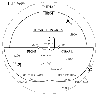
- When GPS TESTING NOTAMs are published and testing is actually occurring, inform pilots requesting or cleared for a RNAV approach that GPS may not be available and request intentions. Do not resume RNAV approach operations until certain that GPS interference is no longer a factor or such GPS testing exercise has ceased.
- During times when pilots report GPS anomalies, request the pilot's intentions and/or clear that aircraft for an alternative approach, if available and operational. Announce to other aircraft requesting an RNAV approach that GPS is reported unavailable and request intentions.
- When clearing an aircraft for an RNAV approach, and a GPS NOTAM is published (a WAAS NOTAM is not issued), both
GPS and WAAS may become unavailable. Therefore, when a GPS anomaly is reported, request the pilot's intentions.
NOTE: WAAS UNAVAILABLE NOTAMs are published to indicate a failure of a WAAS system component. Airborne GPS/WAAS equipment may revert to GPS-only operation which satisfies the requirements for basic RNAV (GPS) approaches to the airport of intended landing or filed alternate airport, if airborne equipment is approved for such operations.
4-8-2. CLEARANCE LIMIT
Issue approach or other clearances, as required, specifying the destination airport as the clearance limit if airport traffic control service is not provided even though this is a repetition of the initial clearance.
- PHRASEOLOGY
- CLEARED TO (destination) AIRPORT
4-8-3. RELAYED APPROACH CLEARANCE
TERMINAL
Include the weather report, when it is required and available, when an approach clearance is relayed through a communication station other than an air carrier company radio. You may do this by telling the station to issue current weather.
4-8-4. ALTITUDE ASSIGNMENT FOR MILITARY HIGH ALTITUDE INSTRUMENT APPROACHES
Altitudes above those shown on the high altitude instrument approach procedures chart may be specified when required for separation.
NOTE: To preclude the possibility of aircraft exceeding rate-of-descent or airspeed limitations, the maximum altitudes which may be assigned for any portion of the high altitude instrument approach procedure will be determined through coordination between the ATC facility concerned and the military authority which originated the high altitude instrument approach procedure.
4-8-5. SPECIFYING ALTITUDE
Specify in the approach clearance the altitude shown in the approach procedures when adherence to that altitude is required for separation. When vertical separation will be provided from other aircraft by pilot adherence to the prescribed maximum, minimum, or mandatory altitudes, the controller may omit specifying the altitude in the approach clearance.
NOTE: Use FAA or NGA instrument approach procedures charts appropriate for the aircraft executing the approach.
4-8-6. CIRCLING APPROACH
- Circling approach instructions may only be given for aircraft landing at airports with operational control towers.
- Include in the approach clearance instructions to circle to the runway in use if landing will be made on a runway other than that aligned with the direction of instrument approach. When the direction of the circling maneuver in relation to the airport/runway is required, state the direction (eight cardinal compass points) and specify a left or right base/downwind leg as appropriate.
- PHRASEOLOGY
- CIRCLE TO RUNWAY (number),
- or
- CIRCLE (direction using eight cardinal compass points) OF THE AIRPORT/RUNWAY FOR A LEFT/RIGHT BASE/DOWNWIND TO RUNWAY (number).
NOTE: Where standard instrument approach procedures (SIAPs) authorize circling approaches, they provide a basic minimum of 300 feet of obstacle clearance at the MDA within the circling area considered. The dimensions of these areas, expressed in distances from the runways, vary for the different approach categories of aircraft. In some cases a SIAP may otherwise restrict circling approach maneuvers.
- Do not issue clearances, such as “extend downwind leg,” which might cause an aircraft to exceed the circling approach area distance from the runways within which required circling approach obstacle clearance is assured.
4-8-7. SIDE-STEP MANEUVER
TERMINAL
Side-step Maneuver. When authorized by an instrument approach procedure, you may clear an aircraft for an approach to one runway and inform the aircraft that landing will be made on a parallel runway.
- EXAMPLE
- “Cleared I-L-S Runway seven left approach. Side-step to runway seven right.”
NOTE: Side-step maneuvers require higher weather minima/ MDA. These higher minima/MDA are published on the instrument approach charts.
4-8-8. COMMUNICATIONS RELEASE
interpretation 8If an IFR aircraft intends to land at an airport not served by a tower or FSS, approve a change to the advisory service frequency when you no longer require direct communications.
- PHRASEOLOGY
- CHANGE TO ADVISORY FREQUENCY APPROVED.
NOTE: An expeditious frequency change permits the aircraft to receive timely local airport traffic information in accordance with AC 90-66, Non-Towered Airport Flight Operations.
4-8-9. MISSED APPROACH
Except in the case of a VFR aircraft practicing an instrument approach, an approach clearance automatically authorizes the aircraft to execute the missed approach procedure depicted for the instrument approach being flown. An alternate missed approach procedure as published on the appropriate FAA Form 8260 or appropriate military form may be assigned when necessary. After an aircraft commences a missed approach, it may be vectored at or above the MVA/MIA, or follow the provisions of paragraph 5-6-3, Vectors Below Minimum Altitude.
- NOTE:
- 1. Alternate missed approach procedures are published on the appropriate FAA Form 8260 or appropriate military form and require a detailed clearance when they are issued to the pilot.
- 2. In the event of a missed approach involving a turn, unless otherwise cleared, the pilot will proceed to the missed approach point before starting that turn.
- 3. Pilots must advise ATC when intending to apply cold temperature compensation and of the amount of compensation required. Pilots will not apply altitude compensation, unless authorized, when assigned an altitude if provided an initial heading to fly or radar vectors in lieu of published missed approach procedures. Consideration should be given to vectoring aircraft at or above the requested compensating altitude if possible.
- REFERENCE
- FAA Order JO 7110.65, Para 4-8-11, Practice Approaches.
- FAA Order JO 7110.65, Para 5-6-3, Vectors Below Minimum Altitude.
- FAA Order JO 7110.65, Para 5-8-3, Successive or Simultaneous Departures.
- FAA Order 8260.19, Flight Procedures and Airspace, Para 8-6-6
- FAA Order 8260.3, United States Standard for Terminal Instrument Procedures (TERPS), Para 2-8-1 and Chapter 16.
- AIM, Paragraph 5-5-5, Missed Approach.
4-8-10. APPROACH INFORMATION
Specify the following in the approach clearance when the pilot says he/she is unfamiliar with the procedure:
- Initial approach altitude.
- Direction and distance from the holding fix within which procedure turn is to be completed.
- Altitude at which the procedure turn is to be made.
- Final approach course and altitude.
- Missed approach procedures if considered necessary.
- PHRASEOLOGY
- INITIAL APPROACH AT (altitude), PROCEDURE TURN AT (altitude), (number) MINUTES/MILES (direction), FINAL APPROACH ON (name of NAVAID) (specified) COURSE/RADIAL/AZIMUTH AT (altitude).
- Applicable notations on instrument approach charts which levy on the pilot the responsibility to comply with or act on an instruction; for example, “Straight-in minima not authorized at night,” “Procedure not authorized when glideslope/glidepath not used,” “Use of procedure limited to aircraft authorized to use airport,” “Procedure not authorized at night,” or a Snowflake icon indicating mandatory cold temperature compensation.
4-8-11. PRACTICE APPROACHES
interpretation 12Except for military aircraft operating at military airfields, ensure that neither VFR nor IFR practice approaches disrupt the flow of other arriving and departing IFR or VFR aircraft. Authorize, withdraw authorization, or refuse to authorize practice approaches as traffic conditions require. Normally, approaches in progress should not be terminated.
NOTE: The priority afforded other aircraft over practice instrument approaches is not intended to be so rigidly applied that it causes grossly inefficient application of services.
- Separation.
- IFR aircraft practicing instrument approaches must be afforded approved separation in accordance with Chapter 3, Chapter 4, Chapter 5, Chapter 6, and Chapter 7 minima until:
- (a) The aircraft lands, and the flight is terminated, or
- (b) The pilot cancels the flight plan.
- Where procedures require application of IFR separation to VFR aircraft practicing instrument approaches, IFR separation in accordance with Chapter 3, Chapter 4, Chapter 5, Chapter 6, and Chapter 7 must be provided. Controller responsibility for separation begins at the point where the approach clearance becomes effective. Except for super or heavy aircraft, 500 feet vertical separation may be applied between VFR aircraft and between a VFR and an IFR aircraft.
- REFERENCE
- FAA Order JO 7210.3, Para 6-4-4, Practice Instrument Approaches.
- FAA Order JO 7210.3, Para 10-4-5, Practice Instrument Approaches.
- Where separation services are not provided to VFR aircraft practicing instrument approaches, the controller must;
- (a) Instruct the pilot to maintain VFR.
- (b) Advise the pilot that separation services are not provided.
- PHRASEOLOGY
- “(Aircraft identification) MAINTAIN VFR, PRACTICE APPROACH APPROVED, NO SEPARATION SERVICES PROVIDED.”
- (c) Provide traffic information or advise the pilot to contact the appropriate facility.
- If an altitude is assigned, including at or above/below altitudes, the altitude specified must meet MVA, minimum safe altitude, or minimum IFR altitude criteria.
- All VFR aircraft must be instructed to maintain VFR on initial contact or as soon as possible thereafter.
NOTE: This advisory is intended to remind the pilot that even though ATC is providing IFR-type instructions, the pilot is responsible for compliance with the applicable parts of the CFR governing VFR flight.
- IFR aircraft practicing instrument approaches must be afforded approved separation in accordance with Chapter 3, Chapter 4, Chapter 5, Chapter 6, and Chapter 7 minima until:
- Missed Approaches.
- Unless alternate instructions have been issued, IFR aircraft are automatically authorized to execute the missed approach depicted for the instrument approach being flown.
- VFR aircraft are not automatically authorized to execute the missed approach procedure. This authorization must be specifically requested by the pilot and approved by the controller. When a missed approach has been approved and the practice approach is conducted in accordance with paragraph 4-8-11 a2, separation must be provided throughout the procedure including the missed approach. If the practice approach is conducted in accordance with paragraph 4-8-11 a3, separation services are not required during the missed approach.
4-8-12. LOW APPROACH AND TOUCH-AND-GO
Consider an aircraft cleared for a touch-and-go, low approach, or practice approach as an arriving aircraft until that aircraft touches down or crosses the landing threshold; thereafter, consider the aircraft as a departing aircraft. Before the aircraft begins its final descent, issue the appropriate departure instructions the pilot is to follow upon completion of the approach (in accordance with para 4-3-2, Departure Clearances). Climb-out instructions must include a specific heading or a route of flight and altitude, except when the aircraft will maintain VFR and contact the tower.
- EXAMPLE
- “After completing low approach, climb and maintain six thousand. Turn right, heading three six zero.”
- “Maintain VFR, contact tower.”
- (Issue other instructions as appropriate.)
NOTE: Climb-out instructions may be omitted after the first approach if instructions remain the same.