Section 10. Arrival Procedures and Separation
- Views Views: 2,910
- Last updated Last updated:
-
Sub-pages:
- 3-10-1. LANDING INFORMATION
- 3-10-10. ALTITUDE RESTRICTED LOW APPROACH
- 3-10-11. CLOSED TRAFFIC
- 3-10-12. OVERHEAD MANEUVER
- 3-10-2. FORWARDING APPROACH INFORMATION BY NONAPPROACH CONTROL FACILITIES
- 3-10-3. SAME RUNWAY SEPARATION
- 3-10-4. INTERSECTING RUNWAY/INTERSECTING FLIGHT PATH SEPARATION
- 3-10-5. LANDING CLEARANCE
- 3-10-6. ANTICIPATING SEPARATION
- 3-10-7. LANDING CLEARANCE WITHOUT VISUAL OBSERVATION
- 3-10-8. WITHHOLDING LANDING CLEARANCE
- 3-10-9. RUNWAY EXITING
Section 10. Arrival Procedures and Separation
3-10-1. LANDING INFORMATION
Provide current landing information, as appropriate, to arriving aircraft. Landing information contained in the ATIS broadcast may be omitted if the pilot states the appropriate ATIS code. Runway, wind, and altimeter may be omitted if a pilot uses the phrase “have numbers.” Issue landing information by including the following:
NOTE: Pilot use of “have numbers” does not indicate receipt of the ATIS broadcast.
- Specific traffic pattern information (may be omitted if the aircraft is to circle the airport to the left).
- PHRASEOLOGY
- ENTER LEFT/RIGHT BASE.
- STRAIGHT-IN.
- MAKE STRAIGHT-IN.
- STRAIGHT-IN APPROVED.
- RIGHT TRAFFIC.
- MAKE RIGHT TRAFFIC.
- RIGHT TRAFFIC APPROVED.
- CONTINUE.
NOTE: Additional information should normally be issued with instructions to continue. Example: “continue, report one mile final”; “continue, expect landing clearance two mile final”; etc.
- Runway in use.
- Surface wind.
- Altimeter setting.
- Any supplementary information.
- Clearance to land.
- Requests for additional position reports. Use prominent geographical fixes which can be easily recognized from the air, preferably those depicted on sectional charts. This does not preclude the use of the legs of the traffic pattern as reporting points.
NOTE: At some locations, VFR checkpoints are depicted on sectional aeronautical and terminal area charts. In selecting geographical fixes, depicted VFR checkpoints are preferred unless the pilot exhibits a familiarity with the local area.
- Ceiling and visibility if either is below basic VFR minima.
- Low level wind shear or microburst advisories when available.
- Issue braking action for the runway in use as received from pilots when braking action advisories are in effect.
- Runway Condition Codes. Furnish RwyCC, as received from the Airport Operator, to aircraft via the ATIS.
- For opposite direction arrival operations, controllers may verbally issue the RwyCC, as identified in the FICON NOTAM, in reverse order. Controllers must not include reversed RwyCC on the ATIS broadcast.
- If the pilot does not indicate the appropriate ATIS code, and when a runway has been shortened, controllers must ensure that pilots receive the runway number combined with a shortened announcement for all arriving aircraft.
3-10-2. FORWARDING APPROACH INFORMATION BY NONAPPROACH CONTROL FACILITIES
- Forward the following, as appropriate, to the control facility having IFR jurisdiction in your area. You may eliminate those items that, because of local conditions or situations, are fully covered in a letter of agreement or a facility directive.
- When you clear an arriving aircraft for a visual approach.
- Aircraft arrival time.
- Cancellation of IFR flight plan.
- Information on a missed approach, unreported, or overdue aircraft.
- Runway in use.
- Weather as required.
- When the weather is below 1,000 feet or 3 miles or the highest circling minimums, whichever is greater, issue current weather to aircraft executing an instrument approach if it changes from that on the ATIS or that previously forwarded to the center/approach control.
3-10-3. SAME RUNWAY SEPARATION
- Separate an arriving aircraft from another aircraft using the same runway by ensuring that the arriving aircraft does not cross the landing threshold until one of the following conditions exists or unless authorized in para 3-10-10, Altitude Restricted Low Approach.
- The other aircraft has landed and is clear of the runway. (See FIG 3-10-1.) Between sunrise and sunset, if you can determine distances by reference to suitable landmarks and the other aircraft has landed, it need not be clear of the runway if the following minimum distance from the landing threshold exists:
- REFERENCE
- P/CG Term - Clear of the Runway.
FIG 3-10-1 Same Runway Separation 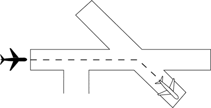
- (a) When a Category I aircraft is landing behind a Category I or II- 3,000 feet. (See FIG 3-10-2.)
FIG 3-10-2 Same Runway Separation 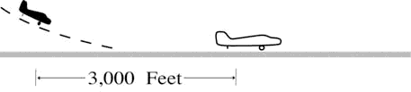
- (b) When a Category II aircraft is landing behind a Category I or II- 4,500 feet.
(See FIG 3-10-3.)
FIG 3-10-3 Same Runway Separation 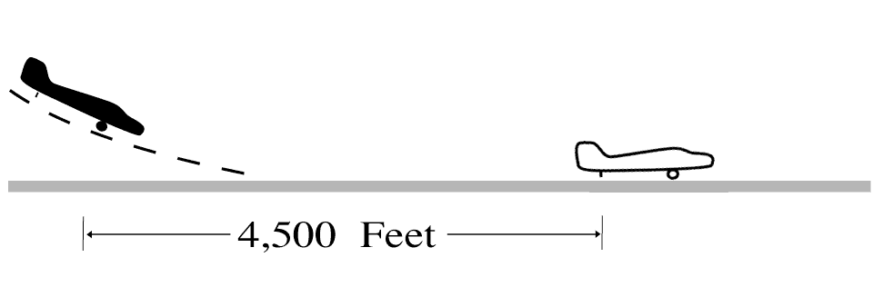
- The other aircraft has departed and crossed the runway end. (See FIG 3-10-4). If you can determine distances by reference to suitable landmarks and the other aircraft is airborne, it need not have crossed the runway end if the following minimum distance from the landing threshold exists:
- (a) Category I aircraft landing behind Category I or II- 3,000 feet.
- (b) Category II aircraft landing behind Category I or II- 4,500 feet.
- (c) When either is a category III aircraft- 6,000 feet. (See FIG 3-10-5.)
FIG 3-10-4 Same Runway Separation 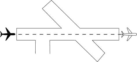
FIG 3-10-5 Same Runway Separation 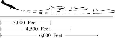
- When the succeeding aircraft is a helicopter, visual separation may be applied in lieu of using distance minima.
WAKE TURBULENCE APPLICATION
- The other aircraft has landed and is clear of the runway. (See FIG 3-10-1.) Between sunrise and sunset, if you can determine distances by reference to suitable landmarks and the other aircraft has landed, it need not be clear of the runway if the following minimum distance from the landing threshold exists:
- Issue wake turbulence advisories, and the position, altitude if known, and the direction of flight of:
- The super or heavy to aircraft landing behind a departing/arriving super or heavy on the same or parallel runways separated by less than 2,500 feet.
- The B757/large aircraft to a small aircraft landing behind a departing/arriving B757/large aircraft on the same or parallel runways separated by less than 2,500 feet.
- REFERENCE
- AC 90-23, Aircraft Wake Turbulence, Para 12, Pilot Responsibility.
- FAA Order JO 7110.65, Para 3-10-10, Altitude Restricted Low Approach.
- EXAMPLE
- “Runway two seven left cleared to land, caution wake turbulence, heavy Boeing 747 departing runway two seven right.”
- “Number two follow Boeing 757 on 2-mile final. Caution wake turbulence.”
- “Traffic, Boeing 737 on 2 mile final to the parallel runway, runway two six right, cleared to land. Caution wake turbulence.”
3-10-4. INTERSECTING RUNWAY/INTERSECTING FLIGHT PATH SEPARATION
Issue traffic information to each aircraft operating on intersecting runways.
- Separate an arriving aircraft using one runway from another aircraft using an intersecting runway or a nonintersecting runway when the flight paths intersect by ensuring that the arriving aircraft does not cross the landing threshold or flight path of the other aircraft until one of the following conditions exists:
- The preceding aircraft has departed and passed the intersection/flight path or is airborne and turning to avert any conflict. (See FIG 3-10-6 and FIG 3-10-7.)
FIG 3-10-6 Intersecting Runway Separation 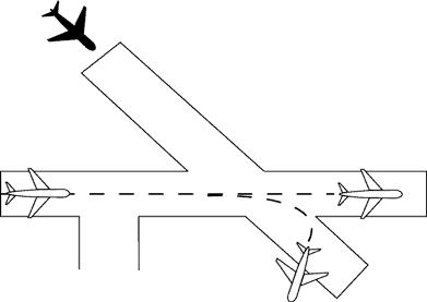
FIG 3-10-7 Intersecting Runway Separation 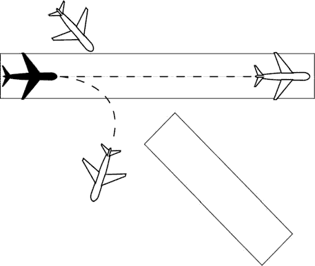
- A preceding arriving aircraft is clear of the landing runway, completed landing roll and will hold short of the intersection/flight path, or has passed the intersection/flight path. (See FIG 3-10-8 and FIG 3-10-9.)
FIG 3-10-8 Intersecting Runway Separation 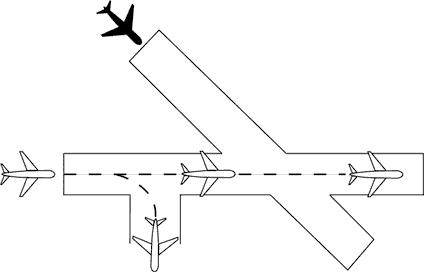
FIG 3-10-9 Intersecting Runway Separation 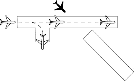
NOTE: When visual separation is being applied by the tower, appropriate control instructions and traffic advisories must be issued to ensure go around or missed approaches avert any conflict with the flight path of traffic on the other runway.
- The preceding aircraft has departed and passed the intersection/flight path or is airborne and turning to avert any conflict. (See FIG 3-10-6 and FIG 3-10-7.)
- USA/USAF/USN NOT APPLICABLE. An aircraft may be authorized to takeoff from one runway while another aircraft lands simultaneously on an intersecting runway or an aircraft lands on one runway while another aircraft lands simultaneously on an intersecting runway, or an aircraft lands to hold short of an intersecting taxiway or some other predetermined point such as an approach/departure flight path using procedures specified in the current LAHSO directive. The procedure must be approved by the air traffic manager and be in accordance with a facility directive. The following conditions apply:
NOTE: Application of these procedures does not relieve controllers from the responsibility of providing other appropriate separation contained in this order.
- REFERENCE
- FAA Order JO 7210.3, Para 10-3-7, Land and Hold Short Operations (LAHSO).
- A simultaneous takeoff and landing operation must only be conducted in VFR conditions.
- Instruct the landing aircraft to hold short of the intersecting runway being used by the aircraft taking off. In the case of simultaneous landings and no operational benefit is lost, restrict the aircraft of the lesser weight category (if known). LAHSO clearances must only be issued to aircraft that are listed in the current LAHSO directive, whose Available Landing Distance (ALD) does not exceed the landing distance requirement for the runway condition.
- PHRASEOLOGY
- HOLD SHORT OF RUNWAY (runway number), (traffic, type aircraft or other information).
NOTE: Pilots who prefer to use the full length of the runway or a runway different from that specified are expected to advise ATC prior to landing.
- Issue traffic information to both aircraft involved and obtain an acknowledgment from each. Request a read back of hold short instructions when they are not received from the pilot of the restricted aircraft.
- EXAMPLE
- 1. “Runway one eight cleared to land, hold short of runway one four left, traffic, (type aircraft) landing runway one four left.”
(When pilot of restricted aircraft responds with only acknowledgment):
“Runway one four left cleared to land, traffic, (type aircraft) landing runway one eight will hold short of the intersection.”
“Read back hold short instructions.”
- 2. “Runway three six cleared to land, hold short of runway three three, traffic, (type aircraft) departing runway three three.”
“Traffic, (type aircraft) landing runway three six will hold short of the intersection, runway three three cleared for takeoff.”
- Issue the measured distance from the landing threshold to the hold short point rounded “down” to the nearest 50-foot increment if requested by either aircraft.
- EXAMPLE
- “Five thousand fifty feet available.”
- The conditions in subparas b2, 3, and 4 must be met in sufficient time for the pilots to take other action, if desired, and no later than the time landing clearance is issued.
- Land and Hold Short runways must be free of any contamination as described in the current LAHSO directive, with no reports that braking action is less than good.
- There is no tailwind for the landing aircraft restricted to hold short of the intersection. The wind may be described as “calm” when appropriate.
- The aircraft required landing distances are listed in the current LAHSO directive.
- STOL aircraft operations are in accordance with a letter of agreement with the aircraft operator/pilot or the pilot confirms that it is a STOL aircraft.
WAKE TURBULENCE APPLICATION
- Separate aircraft landing behind a departing aircraft on a crossing runway if the arrival will fly through the airborne path of the departure by the appropriate radar separation or the following interval: (See FIG 3-10-10):
- Heavy, large, or small behind super - 3 minutes.
- Heavy, large, or small behind heavy - 2 minutes.
- Small behind B757 - 2 minutes.
- Issue wake turbulence cautionary advisories, the position, altitude if known, and direction of flight of the super, heavy, or B757 to:
FIG 3-10-10 Intersecting Runway Separation 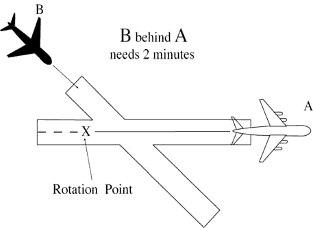
- All aircraft landing on a crossing runway behind a departing super or heavy, or a small aircraft landing on a crossing runway behind a departing B757, if the arrival flight path will cross the takeoff path behind the departing aircraft rotation point. (See FIG 3-10-11.)
FIG 3-10-11 Intersecting Runway Separation 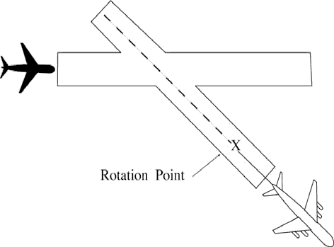
- EXAMPLE
- “Runway niner cleared to land. Caution wake turbulence, heavy C-One Forty One departing runway one five.”
- All VFR aircraft landing on a crossing runway behind an arriving super or heavy, and VFR small aircraft landing on a crossing runway behind a B757, if the arrival flight paths will cross. (See FIG 3-10-12.)
FIG 3-10-12 Intersecting Runway Separation 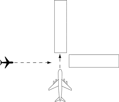
- EXAMPLE
- “Runway niner cleared to land. Caution wake turbulence, Boeing Seven Fifty Seven landing runway three six.”
- All aircraft landing on a crossing runway behind a departing super or heavy, or a small aircraft landing on a crossing runway behind a departing B757, if the arrival flight path will cross the takeoff path behind the departing aircraft rotation point. (See FIG 3-10-11.)
3-10-5. LANDING CLEARANCE
- When issuing a clearance to land, first state the runway number followed by the landing clearance. If the landing runway is changed, controllers must preface the landing clearance with “Change to runway” followed by the runway number. Controllers must then restate the runway number followed by the landing clearance.
- PHRASEOLOGY
- RUNWAY (number) CLEARED TO LAND.
- or
- CHANGE TO RUNWAY (number, RUNWAY (number)CLEARED TO LAND.
NOTE: The purpose of the “change to runway” phraseology and restating the runway number is to emphasize to the pilot that they are being cleared to land on a runway other than what they were expecting.
- When you become aware that an aircraft is aligned with the wrong surface, inform the pilot and:
- Issue control instructions/clearances, or
- EXAMPLE
- “United four twenty three, go-around, you appear to be aligned with the wrong runway.”
- “American sixty three, go-around, you appear to be aligned with a taxiway.”
- “Southwest two thirty nine, you appear to be aligned with Runway 27 Left (pertinent information), Runway 27 Left, cleared to land.”
- If time permits, verify the pilot is aligned with the correct runway. Issue control instructions/clearances as necessary.
- EXAMPLE
- “Twin Cessna four one four lima bravo, verify you are aligned with Runway 27 Left.”
- Issue control instructions/clearances, or
- Procedures.
- Facilities without a safety logic system or facilities with the safety logic system inoperative or in the limited configuration must not clear an aircraft for a full-stop, touch-and-go, stop-and-go, option, or unrestricted low approach when a departing aircraft has been instructed to line up and wait or is holding in position on the same runway. The landing clearance may be issued once the aircraft in position has started takeoff roll.
- Facilities using safety logic in the full core alert runway configuration may issue a landing clearance, full-stop, touch-and-go, stop-and-go, option, or unrestricted low approach to an arriving aircraft with an aircraft holding in position or taxiing to LUAW on the same runway except when reported weather conditions are less than ceiling 800 feet or visibility less than 2 miles.
- Inform the closest aircraft that is requesting a full-stop, touch-and-go, stop-and-go, option, or unrestricted low approaches when there is traffic authorized to line up and wait on the same runway.
- EXAMPLE
- “Delta One, Runway One-Eight, continue, traffic holding in position.”
- “Delta One, Runway One-Eight, cleared to land. Traffic holding in position.”
- “Twin Cessna Four Four Golf, Runway One-Niner base approved, traffic holding in position.”
- “Baron Two Five Foxtrot, Runway One-Niner Right extend downwind, tower will call your base, traffic holding in position.”
- USA/USN/USAF. Issue runway identifier along with surface wind when clearing an aircraft to land, touch and go, stop and go, low approach, or the option.
- PHRASEOLOGY
- RUNWAY (number), WIND (surface wind direction and velocity), CLEARED TO LAND.
NOTE: A clearance to land means that appropriate separation on the landing runway will be ensured. A landing clearance does not relieve the pilot from compliance with any previously issued restriction.
- Whenever a runway length has been temporarily or permanently shortened, state the word “shortened” immediately following the runway number as part of the landing clearance. This information must be issued in conjunction with the landing clearance.
- The addition of “shortened” must be included in the landing clearance for the duration of the construction project when the runway is temporarily shortened.
- The addition of “shortened” must be included in the landing clearance until the Chart Supplement U.S. is updated to include the change(s) when the runway is permanently shortened.
- PHRASEOLOGY
- RUNWAY (number) SHORTENED, CLEARED TO LAND.
- EXAMPLE
- “Runway Two-Seven shortened, cleared to land.”
- If landing clearance is temporarily withheld, insert the word “shortened” immediately after the runway number to advise the pilot to continue.
- PHRASEOLOGY
- RUNWAY (number) SHORTENED, CONTINUE.
- EXAMPLE
- “Runway Two-Seven shortened, continue.”
- REFERENCE
- FAA Order JO 7210.3, Para 10-3-12, Airport Construction
- FAA Order JO 7210.3, Para 10-3-13, Change in Runway Length Due to Construction
3-10-6. ANTICIPATING SEPARATION
- Landing clearance to succeeding aircraft in a landing sequence need not be withheld if you observe the positions of the aircraft and determine that prescribed runway separation will exist when the aircraft crosses the landing threshold. Issue traffic information to the succeeding aircraft if a preceding arrival has not been previously reported and when traffic will be departing prior to their arrival.
- EXAMPLE
- “American Two Forty-Five, Runway One-Eight, cleared to land, number two following a United Seven-Thirty-Seven two mile final. Traffic will depart prior to your arrival.”
- “American Two Forty-Five, Runway One-Eight, cleared to land. Traffic will depart prior to your arrival.”
NOTE: Landing sequence number is optional at tower facilities where the arrival sequence to the runway is established by the approach control.
- Anticipating separation must not be applied when conducting LUAW operations, except as authorized in paragraph 3-10-5 b2. Issue applicable traffic information when using this provision.
- EXAMPLE
- “American Two Forty-Five, Runway One-Eight, cleared to land. Traffic will be a Boeing Seven-Fifty-Seven holding in position.”
- REFERENCE
- P/CG Term - Clear of the Runway.
3-10-7. LANDING CLEARANCE WITHOUT VISUAL OBSERVATION
When an arriving aircraft reports at a position where he/she should be seen but has not been visually observed, advise the aircraft as a part of the landing clearance that it is not in sight and restate the landing runway.
- PHRASEOLOGY
- NOT IN SIGHT, RUNWAY (number) CLEARED TO LAND.
NOTE: Aircraft observance on the CTRD satisfies the visually observed requirement.
3-10-8. WITHHOLDING LANDING CLEARANCE
Do not withhold a landing clearance indefinitely even though it appears a violation of Title 14 of the Code of Federal Regulations has been committed. The apparent violation might be the result of an emergency situation. In any event, assist the pilot to the extent possible.
3-10-9. RUNWAY EXITING
- Instruct aircraft where to turn-off the runway after landing, when appropriate, and advise the aircraft to hold short of a runway or taxiway if required for traffic.
- PHRASEOLOGY
- TURN LEFT/RIGHT (taxiway/runway), or
- IF ABLE, TURN LEFT/RIGHT (taxiway/runway)
- and if required
- HOLD SHORT OF (runway).
NOTE: Runway exiting or taxi instructions should not normally be issued to an aircraft prior to, or immediately after, touchdown.
- Taxi instructions must be provided to the aircraft by the local controller when:
- Compliance with ATC instructions will be required before the aircraft can change to ground control, or
- The aircraft will be required to enter an active runway in order to taxi clear of the landing runway.
- EXAMPLE
- “U.S. Air Ten Forty Two, turn right next taxiway, cross runway two one, contact ground point seven.”
- “U.S. Air Ten Forty Two, turn right on Alfa/next taxiway, cross Bravo, hold short of Charlie, contact ground point seven.”
- NOTE:
- 1. An aircraft is expected to taxi clear of the runway unless otherwise directed by ATC. Pilots must not exit the landing runway on to an intersecting runway unless authorized by ATC. In the absence of ATC instructions, an aircraft should taxi clear of the landing runway by clearing the hold position marking associated with the landing runway even if that requires the aircraft to protrude into or enter another taxiway/ramp area. This does not authorize an aircraft to cross a subsequent taxiway or ramp after clearing the landing runway.
- REFERENCE
- P/CG Term - Clear of the Runway.
- 2. The pilot is responsible for ascertaining when the aircraft is clear of the runway by clearing the runway holding position marking associated with the landing runway.
- Ground control and local control must protect a taxiway/runway/ramp intersection if an aircraft is required to enter that intersection to clear the landing runway.
- REFERENCE
- FAA Order JO 7210.3, Para 10-1-7, Use of Active Runways.
- Request a read back of runway hold short instructions when not received from the pilot.
- EXAMPLE
- “American Four Ninety-two, turn left at Taxiway Charlie, hold short of Runway 27 Right.”
- or
- “American Four Ninety-two, turn left at Charlie, hold short of Runway 27 Right.”
- “American Four Ninety Two, Roger.”
- “American Four Ninety-two, read back hold instructions.”
NOTE: Read back hold instructions phraseology may be initiated for any point on a movement area when the controller believes the read back is necessary.
3-10-10. ALTITUDE RESTRICTED LOW APPROACH
A low approach with an altitude restriction of not less than 500 feet above the airport may be authorized except over an aircraft in takeoff position or a departure aircraft. Do not clear aircraft for restricted altitude low approaches over personnel unless airport authorities have advised these personnel that the approaches will be conducted. Advise the approaching aircraft of the location of applicable ground traffic, personnel, or equipment.
- NOTE:
- 1. The 500 feet restriction is a minimum. Higher altitudes should be used when warranted. For example, 1,000 feet is more appropriate for super or heavy aircraft operating over unprotected personnel or small aircraft on or near the runway.
- 2. This authorization includes altitude restricted low approaches over preceding landing or taxiing aircraft. Restricted low approaches are not authorized over aircraft in takeoff position or departing aircraft.
- PHRASEOLOGY
- CLEARED LOW APPROACH AT OR ABOVE (altitude). TRAFFIC (description and location).
- REFERENCE
- FAA Order JO 7110.65, Para 3-1-5, Vehicles/Equipment/Personnel on Runways.
- FAA Order JO 7110.65, Para 3-1-6, Traffic Information.
- FAA Order JO 7110.65, Para 3-2-1, Light Signals.
- FAA Order JO 7110.65, Para 3-3-3, Timely Information.
- FAA Order JO 7110.65, Para 3-9-4, Line Up and Wait (LUAW).
- FAA Order JO 7110.65, Para 3-10-3, Same Runway Separation.
3-10-11. CLOSED TRAFFIC
Approve/disapprove pilot requests to remain in closed traffic for successive operations subject to local traffic conditions.
- PHRASEOLOGY
- LEFT/RIGHT (if required) CLOSED TRAFFIC APPROVED. REPORT (position if required),
- or
- UNABLE CLOSED TRAFFIC, (additional information as required).
NOTE: Segregated traffic patterns for helicopters to runways and other areas may be established by letter of agreement or other local operating procedures.
3-10-12. OVERHEAD MANEUVER
Issue the following to arriving aircraft that will conduct an overhead maneuver:
- Pattern altitude and direction of traffic. Omit either or both if standard or when you know the pilot is familiar with a nonstandard procedure.
- PHRASEOLOGY
- PATTERN ALTITUDE (altitude). RIGHT TURNS.
- Request for report on initial approach.
- PHRASEOLOGY
- REPORT INITIAL.
- “Break” information and request for pilot report. Specify the point of “break” only if nonstandard. Request the pilot to report “break” if required for traffic or other reasons.
- PHRASEOLOGY
- BREAK AT (specified point). REPORT BREAK.
- Overhead maneuver patterns are developed at airports where aircraft have an operational need to conduct the maneuver. An aircraft conducting an overhead maneuver is VFR and the IFR flight plan is cancelled when the aircraft reaches the “initial point” on the initial approach portion of the maneuver. The existence of a standard overhead maneuver pattern does not eliminate the possible requirement for an aircraft to conform to conventional rectangular patterns if an overhead maneuver cannot be approved.
NOTE: Aircraft operating to an airport without a functioning control tower must initiate cancellation of the IFR flight plan prior to executing the overhead maneuver or after landing.
FIG 3-10-13 Overhead Maneuver 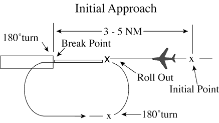
- EXAMPLE
- “Air Force Three Six Eight, Runway Six, wind zero seven zero at eight, pattern altitude six thousand, report initial.”
- “Air Force Three Six Eight, break at midfield, report break.”
- “Air Force Three Six Eight, cleared to land.”
- “Alfa Kilo Two Two, Runway Three One, wind three three zero at one four, right turns, report initial.”
- “Alfa Kilo Two Two, report break.” “Alfa Kilo Two Two, cleared to land.”
- Timely and positive controller action is required to prevent a conflict when an overhead pattern could extend into the path of a departing or a missed approach aircraft. Local procedures and/or coordination requirements should be set forth in an appropriate letter of agreement, facility directive, base flying manual etc., when the frequency of occurrence warrants.
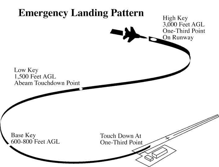
3-10-13. SIMULATED FLAMEOUT (SFO) APPROACHES/EMERGENCY LANDING PATTERN (ELP) OPERATIONS/PRACTICE PRECAUTIONARY APPROACHES
- Authorize military aircraft to make SFO/ELP/ practice precautionary approaches if the following conditions are met:
- A letter of agreement or local operating procedure is in effect between the military flying organization and affected ATC facility.
- (a) Include specific coordination, execution, and approval procedures for the operation.
- (b) The exchange or issuance of traffic information as agreed to in any interfacility letter of agreement is accomplished.
- (c) Include a statement in the procedure that clarifies at which points SFOs/ELPs may/may not be terminated. (See FIG 3-10-14 and FIG 3-10-16.)
- Traffic information regarding aircraft in radio communication with or visible to tower controllers which are operating within or adjacent to the flameout maneuvering area is provided to the SFO/ELP aircraft and other concerned aircraft.
- The high-key altitude or practice precautionary approach maneuvering altitudes of the aircraft concerned are obtained prior to approving the approach. (See FIG 3-10-14 and FIG 3-10-16.)
- NOTE:
- 1. Practice precautionary/SFO/ELP approaches are authorized only for specific aircraft. Any aircraft, however, might make precautionary approaches, when engine failure is considered possible. The practice precautionary approach maneuvering area/altitudes may not conform to the standard SFO/ELP maneuvering area/altitudes.
- 2. SFO/ELP approaches generally require high descent rates. Visibility ahead and beneath the aircraft is greatly restricted.
- 3. Pattern adjustments for aircraft conducting SFOs and ELPs may impact the effectiveness of SFO and ELP training.
- REFERENCE
- FAA Order JO 7110.65, Para 4-8-12, Low Approach and Touch-and-Go.
- FAA Order JO 7610.4, Para 9-3-7, Simulated Flameout (SFO)/Emergency Landing Pattern (ELP) Operations.
- A letter of agreement or local operating procedure is in effect between the military flying organization and affected ATC facility.
- For overhead SFO/ELP approaches:
- Request a report at the entry point.
- PHRASEOLOGY
- REPORT (high or low) KEY (as appropriate).
- Request a report at low key.
- PHRASEOLOGY
- REPORT LOW KEY.
- At low key, issue low approach clearance or alternate instructions.
- REFERENCE
- FAA Order JO 7110.65, Para 3-8-1, Sequence/Spacing Application.
- FAA Order JO 7110.65, Para 10-1-7, Inflight Emergencies Involving Military Fighter-type Aircraft.
- FAA Order JO 7610.4, Para 9-3-7, Simulated Flameout (SFO)/Emergency Landing Pattern (ELP) Operations.
- Request a report at the entry point.
- For straight-in simulation flameout approaches:
- Request a position report from aircraft conducting straight-in SFO approaches.
- PHRASEOLOGY
- REPORT (distance) MILE SIMULATED FLAMEOUT FINAL.
- At the appropriate position on final (normally no closer than 3 miles), issue low approach clearance or alternate instruction. (See FIG 3-10-15.)
- Request a position report from aircraft conducting straight-in SFO approaches.
FIG 3-10-14 Simulated Flameout [1] 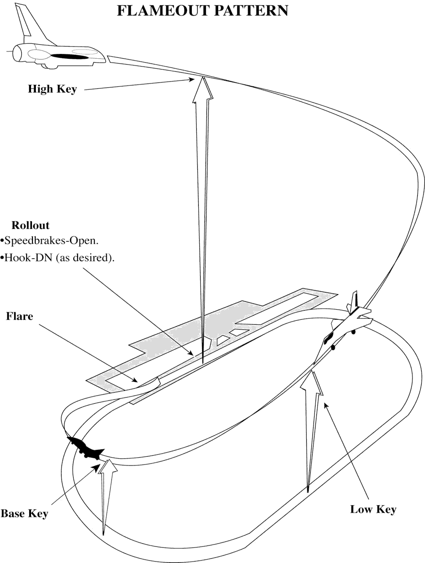
FIG 3-10-15 Simulated Flameout [2] 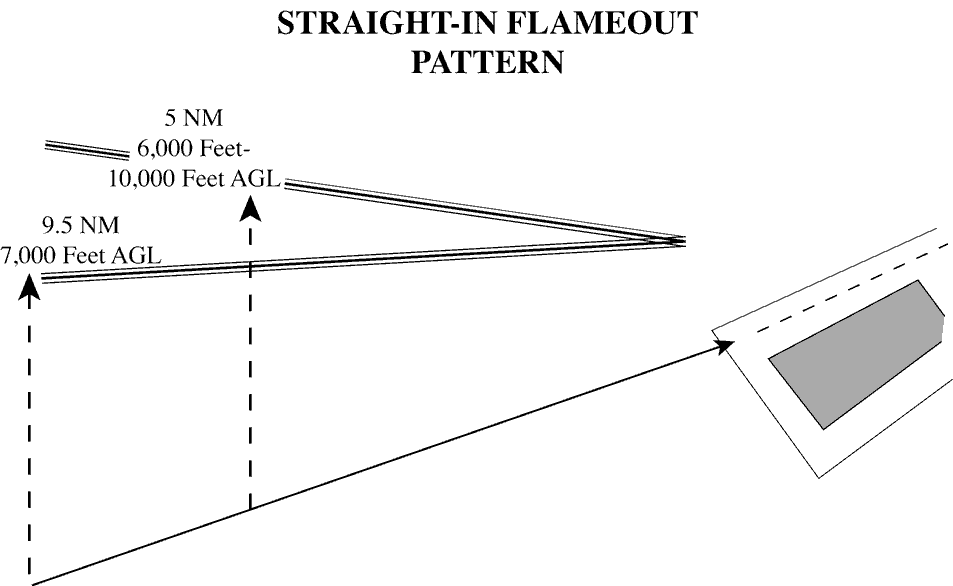
FIG 3-10-16 Emergency Landing Pattern