Section 1. General
2-1-1. ATC SERVICE
interpretation 10- The primary purpose of the ATC system is to prevent a collision involving aircraft operating in the system.
-
In addition to its primary purpose, the ATC system also:
- Provides a safe, orderly, and expeditious flow of air traffic.
- Supports National Security and Homeland Defense missions.
-
The ATC system must provide certain additional services to the extent permitted. The provision of additional
services is not optional on the part of the controller, but rather required when the work situation permits. It is
recognized that the provision of these services may be precluded by various factors, including, but not limited
to:
- Volume of traffic.
- Frequency congestion.
- Quality of surveillance.
- Controller workload.
- Higher priority duties.
- The physical inability to scan and detect situations falling in this category.
-
Controllers must provide air traffic control service in accordance with the procedures and minima in this order,
except when one or more of the following conditions exists:
- A deviation is necessary to conform with ICAO Documents, National Rules of the Air, or special agreements where the U.S. provides air traffic control service in airspace outside the U.S. and its possessions or:
- Other procedures/minima are prescribed in a letter of agreement, FAA directive, or a military document, or:
- A deviation is necessary to assist an aircraft when an emergency has been declared.
NOTE: Pilots are required to abide by CFRs or other applicable regulations regardless of the application of any procedure or minima in this order.
NOTE: These procedures may include altitude reservations, air refueling, fighter interceptor operations, law enforcement, etc.
-
Air Traffic Control services are not provided for model aircraft operating in the NAS or to any UAS operating in
the NAS at or below 400ft AGL.
- NOTE:
- This does not prohibit ATC from providing services to civil and public UAS.
- The provisions of this paragraph apply to model aircraft operating at any altitude. For all other UAS, this paragraph applies only to those UAS operating entirely at or below 400ft AGL.
- REFERENCE
- P/CG Term - Model Aircraft.
2-1-2. DUTY PRIORITY
- Give first priority to separating aircraft and issuing safety alerts as required in this order. Good judgment must be used in prioritizing all other provisions of this order based on the requirements of the situation at hand.
- Provide support to national security and homeland defense activities to include, but not be limited to, reporting of suspicious and/or unusual aircraft/pilot activities.
- REFERENCE
- FAA Order JO 7610.4 Special Operations.
- Provide and/or solicit weather information in accordance with procedures and requirements outlined in this order.
- Provide additional services to the extent possible, contingent only upon higher priority duties and other factors including limitations of radar, volume of traffic, frequency congestion, and workload.
NOTE: Because there are many variables involved, it is virtually impossible to develop a standard list of duty priorities that would apply uniformly to every conceivable situation. Each set of circumstances must be evaluated on its own merit, and when more than one action is required, controllers must exercise their best judgment based on the facts and circumstances known to them. That action which is most critical from a safety standpoint is performed first.
NOTE: Controllers are responsible to become familiar with and stay aware of current weather information needed to perform ATC duties.
2-1-3. PROCEDURAL PREFERENCE
- Use automation procedures in preference to non-automation procedures when workload, communications, and equipment capabilities permit.
- Use automation procedures that provide closed loop clearances in preference to open loop clearances to promote operational advantage for time-based management (TBM) when workload permits. (e.g., a QU route pick that anticipates length of vector and includes the next fix that ties into the route of flight.)
- Use radar separation in preference to nonradar separation when it will be to an operational advantage and workload, communications, and equipment permit.
-
Use nonradar separation in preference to radar separation when the situation dictates that an operational
advantage will be gained.
NOTE: One situation may be where vertical separation would preclude excessive vectoring.
2-1-4. OPERATIONAL PRIORITY
It is recognized that traffic flow may affect the controller's ability to provide priority handling. However, without compromising safety, good judgment must be used in each situation to facilitate the most expeditious movement of priority aircraft. Provide air traffic control service to aircraft on a “first come, first served” basis as circumstances permit, except the following:
NOTE: It is solely the pilot's prerogative to cancel an IFR flight plan. However, a pilot's retention of an IFR flight plan does not afford priority over VFR aircraft. For example, this does not preclude the requirement for the pilot of an arriving IFR aircraft to adjust his/her flight path, as necessary, to enter a traffic pattern in sequence with arriving VFR aircraft.
- An aircraft in distress has the right of way over all other air traffic.
- REFERENCE
- 14 CFR Section 91.113(c).
- Treat air ambulance flights as follows:
- Provide priority handling to civil air ambulance flights when the pilot, in radio transmissions, verbally
identifies the flight by stating “MEDEVAC” followed by the FAA authorized call sign or the full civil
registration letters/numbers. Good judgment must be used in each situation to facilitate the most expeditious
movement of a MEDEVAC aircraft.
NOTE: If a flight plan includes the letter “L” for “MEDEVAC” and/or includes “MEDEVAC” in Item 11 (Remarks) of the flight plan or Item 18 (Other Information) of an international flight plan, the entries are considered informational in nature only and not an identification for operational priority.
- Provide priority handling to AIR EVAC and HOSP flights when verbally requested by the pilot.
If a flight plan includes “HOSP” or “AIR EVAC” in either Item 11 (Remarks) or Item 18 (Other Information) of an international flight plan, the entries are considered informational in nature only and not an identification for operational priority. For aircraft identification in radio transmissions, civilian pilots will use normal call signs when filing “HOSP” and military pilots will use the “EVAC” call sign.
- Assist the pilots of MEDEVAC, AIR EVAC, and HOSP aircraft to avoid areas of significant weather and adverse conditions.
- If requested by a pilot, provide additional assistance (i.e., landline notifications) to expedite ground handling of patients, vital organs, or urgently needed medical materials.
- Provide priority handling to civil air ambulance flights when the pilot, in radio transmissions, verbally
identifies the flight by stating “MEDEVAC” followed by the FAA authorized call sign or the full civil
registration letters/numbers. Good judgment must be used in each situation to facilitate the most expeditious
movement of a MEDEVAC aircraft.
- Provide priority handling and expedite the movement of presidential aircraft and entourage and any rescue
support aircraft as well as related control messages when traffic conditions and communications facilities permit.
NOTE: As used herein the terms presidential aircraft and entourage include aircraft and entourage of the President, Vice President, or other public figures when designated by the White House.
- REFERENCE
- FAA Order JO 7110.65, Para 2-4-20 Aircraft Identification.
- FAA Order JO 7110.65, Para 4-3-2 Departure Clearances.
- FAA Order JO 7210.3, Para 5-1-1 Advance Coordination.
- Provide priority handling and maximum assistance to SAR aircraft performing a SAR mission.
- REFERENCE
- FAA Order JO 7110.65, Para 10-1-3, Providing Assistance.
- Provide priority handling and maximum assistance to expedite the movement of interceptor aircraft on active air defense missions until the unknown aircraft is identified.
- Provide priority handling to NIGHT WATCH aircraft when NAOC (pronounced NA-YOCK) is indicated in the remarks
section of the flight plan or in air/ground communications.
NOTE: The term “NAOC” will not be a part of the call sign but may be used when the aircraft is airborne to indicate a request for special handling.
- REFERENCE
- FAA Order JO 7610.4, Para 12-1-1 Applications.
- Provide priority handling to any civil or military aircraft using the code name “FLYNET.”
- REFERENCE
- FAA Order JO 7110.65, Para 9-2-5, FLYNET.
- FAA Order JO 7610.4, Para 12-4-1 “FLYNET” Flights, Nuclear Emergency Teams.
- Provide priority handling to aircraft using the code name “Garden Plot” only when CARF notifies you that such
priority is authorized. Refer any questions regarding flight procedures to CARF for resolution.
NOTE: Garden Plot flights require priority movement and are coordinated by the military with CARF. State authority will contact the Regional Administrator to arrange for priority of National Guard troop movements within a particular state.
- Provide priority handling to USAF or other government aircraft engaged in aerial sampling/surveying missions
using the call sign "SAMP."
- REFERENCE
- FAA Order JO 7110.65, Para 9-2-17, SAMP FLIGHTS.
- FAA Order JO 7210.3, Para 5-3-2, Aerial Sampling/Surveying For Nuclear Contamination.
- Provide priority handling to Special Air Mission aircraft when SCOOT is indicated in the remarks section of the
flight plan or used in air/ground communications.
NOTE: The term “SCOOT” will not be part of the call sign but may be used when the aircraft is airborne to indicate a request for special handling.
- REFERENCE
- FAA Order JO 7610.4, Para 12-6-1, Applications.
- When requested, provide priority handling to TEAL and NOAA mission aircraft.
- Provide priority handling, as required to expedite Flight Check aircraft.
NOTE: It is recognized that unexpected wind conditions, weather, or heavy traffic flows may affect controller's ability to provide priority or special handling at the specific time requested.
- IFR aircraft must have priority over SVFR aircraft.
- Aircraft operating under the North American Route Program (NRP) are not subject to route limiting restrictions
(e.g., published preferred IFR routes, letter of agreement requirements, standard operating procedures).
- REFERENCE
- FAA Order JO 7110.65, Para 2-3-2, En Route Data Entries.
- FAA Order JO 7110.65, Para 2-2-15, North American Route Program (NRP) Information.
- FAA Order JO 7110.65, Para 4-2-5, Route or Altitude Amendments.
- FAA Order JO 7210.3, Chapter 18, Section 17, North American Route Program.
- If able, provide priority handling to diverted flights. Priority handling may be requested via use of “DVRSN” in
the remarks section of the flight plan or by the flight being placed on the Diversion Recovery Tool (DRT).
- REFERENCE
- FAA Order JO 7210.3, Para 17-4-5, Diversion Recovery.
- If able, provide priority handling to FALLEN HERO flights when "FALLEN HERO" is indicated in the remarks section of the flight plan or requested in air/ground communications.
2-1-5. EXPEDITIOUS COMPLIANCE
- Use the word “immediately” only when expeditious compliance is required to avoid an imminent situation.
- Use the word “expedite” only when prompt compliance is required to avoid the development of an imminent situation. If an “expedite” climb or descent clearance is issued by ATC, and subsequently the altitude to maintain is changed or restated without an expedite instruction, the expedite instruction is canceled.
- In either case, if time permits, include the reason for this action.
2-1-6. SAFETY ALERT
Issue a safety alert to an aircraft if you are aware the aircraft is in a position/altitude that, in your judgment, places it in unsafe proximity to terrain, obstructions, or other aircraft. Once the pilot informs you action is being taken to resolve the situation, you may discontinue the issuance of further alerts. Do not assume that because someone else has responsibility for the aircraft that the unsafe situation has been observed and the safety alert issued; inform the appropriate controller.
- NOTE:
- 1. The issuance of a safety alert is a first priority (see para 2-1-2, Duty Priority) once the controller observes and recognizes a situation of unsafe aircraft proximity to terrain, obstacles, or other aircraft. Conditions, such as workload, traffic volume, the quality/limitations of the radar system, and the available lead time to react are factors in determining whether it is reasonable for the controller to observe and recognize such situations. While a controller cannot see immediately the development of every situation where a safety alert must be issued, the controller must remain vigilant for such situations and issue a safety alert when the situation is recognized.
- 2. Recognition of situations of unsafe proximity may result from MSAW/E-MSAW, automatic altitude readouts, Conflict/Mode C Intruder Alert, observations on a PAR scope, or pilot reports.
- 3. Once the alert is issued, it is solely the pilot's prerogative to determine what course of action, if any, will be taken.
- Terrain/Obstruction Alert. Immediately issue/ initiate an alert to an aircraft if you are aware the aircraft is at an altitude that, in your judgment, places it in unsafe proximity to terrain and/or obstructions. Issue the alert as follows:
- PHRASEOLOGY
- LOW ALTITUDE ALERT (call sign),
- CHECK YOUR ALTITUDE IMMEDIATELY.
- and, if the aircraft is not yet on final approach,
- THE (as appropriate) MEA/MVA/MOCA/MIA IN YOUR AREA IS (altitude)
- REFERENCE
- P/CG Term - Final Approach - IFR.
- Aircraft Conflict/Mode C Intruder Alert. Immediately issue/initiate an alert to an aircraft if you are aware of another aircraft at an altitude that you believe places them in unsafe proximity. If feasible, offer the pilot an alternate course of action. When an alternate course of action is given, end the transmission with the word “immediately.”
- PHRASEOLOGY
- TRAFFIC ALERT (call sign) (position of aircraft) ADVISE YOU TURN LEFT/RIGHT (heading),
- and/or
- CLIMB/DESCEND (specific altitude if appropriate) IMMEDIATELY.
- EXAMPLE
- “Traffic Alert, Cessna Three Four Juliet, 12'o clock, 1 mile advise you turn left immediately.”
- or
- “Traffic Alert, Cessna Three-Four Juliet, 12'o clock, 1 mile advise you turn left and climb immediately.”
- REFERENCE
- FAA Order JO 7110.65, Para 5-13-1, Conflict Alert (CA) and Mode C Intruder (MCI) Alert.
- FAA Order JO 7110.65, Para 5-13-2, En Route Minimum Safe Altitude Warning (E-MSAW).
- FAA Order JO 7110.65, Para 5-14-6, CA/MCI.
- FAA Order JO 7110.65, Para 5-2-21, Altitude Filters.
- FAA Order JO 7110.65, Para 2-1-21, Traffic Advisories.
2-1-7. INFLIGHT EQUIPMENT MALFUNCTIONS
- When a pilot reports an inflight equipment malfunction, determine the nature and extent of any special handling desired.
- Provide the maximum assistance possible consistent with equipment, workload, and any special handling requested.
- Relay to other controllers or facilities who will subsequently handle the aircraft, all pertinent details concerning the aircraft and any special handling required or being provided.
NOTE: Inflight equipment malfunctions include partial or complete failure of equipment, which may affect either safety, separation standards, and/or the ability of the flight to proceed under IFR, or in Reduced Vertical Separation Minimum (RVSM) airspace, in the ATC system. Controllers may expect reports from pilots regarding VOR, TACAN, ADF, GPS, RVSM capability, or low frequency navigation receivers, impairment of air-ground communications capability, or other equipment deemed appropriate by the pilot (e.g., airborne weather radar). Pilots should communicate the nature and extent of any assistance desired from ATC.
2-1-8. MINIMUM FUEL
If an aircraft declares a state of “minimum fuel,” inform any facility to whom control jurisdiction is transferred of the minimum fuel problem and be alert for any occurrence which might delay the aircraft en route.
NOTE: Use of the term “minimum fuel” indicates recognition by a pilot that his/her fuel supply has reached a state where, upon reaching destination, he/she cannot accept any undue delay. This is not an emergency situation but merely an advisory that indicates an emergency situation is possible should any undue delay occur. A minimum fuel advisory does not imply a need for traffic priority. Common sense and good judgment will determine the extent of assistance to be given in minimum fuel situations. If, at any time, the remaining usable fuel supply suggests the need for traffic priority to ensure a safe landing, the pilot should declare an emergency and report fuel remaining in minutes.
2-1-9. REPORTING ESSENTIAL FLIGHT INFORMATION
Report as soon as possible to the appropriate FSS, airport manager's office, ARTCC, approach control facility, operations office, or military operations office any information concerning components of the NAS or any flight conditions which may have an adverse effect on air safety.
NOTE: FSSs are responsible for classifying and disseminating Notices to Air Missions.
- REFERENCE
- FAA Order JO 7110.65, Para 3-3-3, Timely Information.
- FAA Order JO 7210.3, Para 3-1-2, Periodic Maintenance.
- USN, See OPNAVINST 3721.30.
2-1-10. NAVAID MALFUNCTIONS
- When an aircraft reports a ground-based NAVAID malfunction, take the following actions:
- Request a report from a second aircraft.
- If the second aircraft reports normal operations, continue use and inform the first aircraft. Record the incident on FAA Form 7230-4 or appropriate military form.
- If the second aircraft confirms the malfunction or in the absence of a second aircraft report, activate the standby equipment or request the monitor facility to activate.
- If normal operation is reported after the standby equipment is activated, continue use, record the incident on FAA Form 7230-4 or appropriate military form, and notify technical operations personnel (the Systems Engineer of the ARTCC when an en route aid is involved).
- If continued malfunction is reported after the standby equipment is activated or the standby equipment cannot be activated, inform technical operations personnel and request advice on whether or not the aid should be shut down. In the absence of a second aircraft report, advise the technical operations personnel of the time of the initial aircraft report and the estimated time a second aircraft report could be obtained.
- When an aircraft reports a GPS or WAAS anomaly, request the following information and/or take the following actions:
- Record the following minimum information:
- (a) Aircraft make, model, and call sign.
- (b) Location or position, and altitude at the time where GPS or WAAS anomaly was observed.
- (c) Date/time of occurrence.
- Request a report from a second aircraft.
- Record the incident on FAA Form 7230-4 or appropriate military form.
- Inform other aircraft of the anomaly as specified in paragraph 4-8-1j or k, as applicable.
- PHRASEOLOGY
- ATTENTION ALL AIRCRAFT, GPS REPORTED UNRELIABLE (OR WAAS UNAVAILABLE) IN VICINITY/AREA (position).
- EXAMPLE
- “Attention all aircraft, GPS reported unreliable (or WAAS unavailable) in the area 30 miles south of Waco VOR.”
- Record the following minimum information:
- When a pilot reports a WAAS anomaly, determine from the pilot what indications he or she observes and record the information in accordance with sub-paragraph b above.
2-1-11. USE OF MARSA
- MARSA may only be applied to military operations specified in a letter of agreement or other appropriate FAA or military document.
NOTE: Application of MARSA is a military command prerogative. It will not be invoked indiscriminately by individual units or pilots. It will be used only for IFR operations requiring its use. Commands authorizing MARSA will ensure that its implementation and terms of use are documented and coordinated with the control agency having jurisdiction over the area in which the operations are conducted. Terms of use will assign responsibility and provide for separation among participating aircraft.
- ATC facilities do not invoke or deny MARSA. Their sole responsibility concerning the use of MARSA is to provide separation between military aircraft engaged in MARSA operations and other nonparticipating IFR aircraft.
- DOD must ensure that military pilots requesting special-use airspace/ATCAAs have coordinated with the scheduling agency, have obtained approval for entry, and are familiar with the appropriate MARSA procedures. ATC is not responsible for determining which military aircraft are authorized to enter special-use airspace/ATCAAs.
2-1-12. MILITARY PROCEDURES
Military procedures in the form of additions, modifications, and exceptions to the basic FAA procedure are prescribed herein when a common procedure has not been attained or to fulfill a specific requirement. They must be applied by:
- ATC facilities operated by that military service.
- EXAMPLE
- 1. An Air Force facility providing service for an Air Force base would apply USAF procedures to all traffic regardless of class.
- 2. A Navy facility providing service for a Naval Air Station would apply USN procedures to all traffic regardless of class.
- ATC facilities, regardless of their parent organization (FAA, USAF, USN, USA), supporting a designated military airport exclusively. This designation determines which military procedures are to be applied.
- EXAMPLE
- 1. An FAA facility supports a USAF base exclusively; USAF procedures are applied to all traffic at that base.
- 2. An FAA facility provides approach control service for a Naval Air Station as well as supporting a civil airport; basic FAA procedures are applied at both locations by the FAA facility.
- 3. A USAF facility supports a USAF base and provides approach control service to a satellite civilian airport; USAF procedures are applied at both locations by the USAF facility.
- Other ATC facilities when specified in a letter of agreement.
- EXAMPLE
- A USAF unit is using a civil airport supported by an FAA facility- USAF procedures will be applied as specified in a letter of agreement between the unit and the FAA facility to the aircraft of the USAF unit. Basic FAA procedures will be applied to all other aircraft.
2-1-13. FORMATION FLIGHTS
interpretation 23 interpretation 26Control formation flights as a single aircraft. Separation responsibility between aircraft within the formation rests with the flight leader and the pilots of the other aircraft in the flight. This includes transition periods when aircraft within the formation are maneuvering to attain separation from each other to effect individual control during join-up and breakaway.
- REFERENCE
- P/CG Term - Formation Flight
- FAA Order JO 7610.4, Chapter 12, Section 11. Formation Flight ICAO Annex 2, 3.1.8 Formation Flights
-
Support formation flight join-up for two aircraft when all of the following occur:
- Requested by any participating pilot.
- All participating pilots concur.
- Either of the participating pilots reports the other/s in sight.
- EXAMPLE
- “ROOK01 has EAGLE03 in sight, request formation join-up with EAGLE03 at flight level two zero zero. EAGLE03 will be the lead.”
- “EAGLE03 verify requesting flight join-up with ROOK01.”
- If affirmative:
- “ROOK01 climb and maintain flight level two zero zero. Report (advise) when formation join-up is complete.”
-
If multiple single aircraft request to join-up, multiple formations are joining as one, or aircraft are joining an
established formation, obtain confirmation of required items listed in subparagraph 2-1-13a, from the lead
aircraft.
- REFERENCE
- P/CG Term - Formation Flight
-
After join-up, aircraft beacon code assignment will be determined by formation type.
- For a standard formation only the aircraft acting as the lead will squawk an ATC assigned beacon code. Ensure all other aircraft squawk standby.
-
For a nonstandard formation, each aircraft should squawk an ATC assigned beacon code. Controller discretion
allows aircraft in a nonstandard formation to squawk standby if operationally advantageous.
- REFERENCE
- FAA Order JO 7610.4, Paragraph 12-11-6, Nonstandard Formation Tactics, subparagraph b3
- EXAMPLE
- “N123JP squawk standby.”
- Or
- “N123SP have N123JP squawk standby.”
-
When formation break-up is requested, issue control instructions and/or clearances which will result in approved
separation through the lead or directly to the requesting aircraft in the formation.
- EXAMPLE
- “N5871S requesting flight break-up with N731K. N731K is changing destination to PHL.”
- “N731K squawk 5432, turn right, fly heading zero-seven-zero.
-
“Center, BAMA21. BAMA23 is requesting to RTB.”
“BAMA21 have BAMA23 squawk 5544, descend and maintain flight level one-niner-zero and change to my frequency.” -
“Center, BAMA21. BAMA23 is requesting to RTB.”
“BAMA23 squawk 5544. BAMA23 Radar contact (position if required). Cleared to SSC via direct. Descend and maintain flight level one-niner-zero.”
-
Military and civil formation flights in RVSM airspace.
- Utilize RVSM separation standards for a formation flight, which consists of all RVSM approved aircraft.
- Utilize non-RVSM separation standards for a formation flight at or above FL 290, which does not consist of all RVSM approved aircraft.
- If aircraft are requesting to form a formation flight to FL 290 or above, the controller who issues the clearance creating the formation flight is responsible for ensuring that the proper equipment suffix is entered for the lead aircraft.
- If the flight departs as a formation, and is requesting FL 290 or above, the first center sector must ensure that the proper equipment suffix is entered.
- If the formation flight is below FL 290 and later requests FL 290 or above, the controller receiving the RVSM altitude request must ensure the proper equipment suffix is entered.
- Upon break-up of the formation flight, the controller initiating the break-up must ensure that all aircraft or flights are assigned their proper equipment suffix.
2-1-14. COORDINATE USE OF AIRSPACE
- Ensure that the necessary coordination has been accomplished before you allow an aircraft under your control to enter another controller's area of jurisdiction.
- Before you issue a control instruction directly to a pilot that will change the aircraft's heading, route, speed, or altitude, you must ensure that coordination has been completed with all controllers whose area of jurisdiction is affected by those instructions unless otherwise specified by a letter of agreement or facility directive. If your control instruction will be relayed to the pilot through a source other than another radar controller (FSS, New York Radio, San Francisco Radio, another pilot, etc.), you are still responsible to ensure that all required coordination is completed.
- NOTE:
- 1. It is good operating practice for controllers to confirm that required coordination has been/will be effected, especially in unusual circumstances, such as recently modified sector configurations, airspace changes, route changes, etc.
- 2. Ensuring that all required coordination has been completed does not necessarily imply that the controller issuing the control instruction directly to the pilot has to perform the coordination action.
2-1-15. CONTROL TRANSFER
- Transfer control of an aircraft in accordance with the following conditions:
- At a prescribed or coordinated location, time, fix, or altitude; or,
- At the time a radar handoff and frequency change to the receiving controller have been completed and when authorized by a facility directive or letter of agreement which specifies the type and extent of control that is transferred.
- Transfer control of an aircraft only after eliminating any potential conflict with other aircraft for which you have separation responsibility.
- Assume control of an aircraft only after it is in your area of jurisdiction unless specifically coordinated or as specified by letter of agreement or a facility directive.
2-1-16. SURFACE AREAS
- Coordinate with the appropriate nonapproach control tower on an individual aircraft basis before issuing a clearance which would require flight within a surface area for which the tower has responsibility unless otherwise specified in a letter of agreement.
- REFERENCE
- FAA Order JO 7210.3, Para 4-3-1, Letters of Agreement.
- 14 CFR Section 91.127, Operating on or in the Vicinity of an Airport in Class E Airspace.
- P/CG Term - Surface Area.
- Coordinate with the appropriate control tower for transit authorization when you are providing radar traffic advisory service to an aircraft that will enter another facility's airspace.
NOTE: The pilot is not expected to obtain his/her own authorization through each area when in contact with a radar facility.
- Transfer communications to the appropriate facility, if required, prior to operation within a surface area for which the tower has responsibility.
- REFERENCE
- FAA Order JO 7110.65, Para 2-1-17, Radio Communications Transfer.
- FAA Order JO 7110.65, Para 3-1-11, Surface Area Restrictions.
- FAA Order JO 7110.65, Para 7-6-1, Application.
- 14 CFR Section 91.129, Operations in Class D Airspace.
2-1-17. RADIO COMMUNICATIONS
- Transfer radio communications before an aircraft enters the receiving controller's area of jurisdiction unless otherwise coordinated or specified by a letter of agreement or a facility directive.
- Transfer radio communications by specifying the following:
NOTE: Radio communications transfer procedures may be specified by a letter of agreement or contained in the route description of an MTR as published in the DOD Planning AP/1B (AP/3).
- The facility name or location name and terminal function to be contacted.
TERMINAL: Omit the location name when transferring communications to another controller within your facility, or, when the tower and TRACON share the same name (for example, Phoenix Tower and Phoenix TRACON).
EXCEPTION: Controllers must include the name of the facility when instructing an aircraft to change frequency for final approach guidance. - Frequency to use except the following may be omitted:
- (a) FSS frequency.
- (b) Departure frequency if previously given or published on a SID chart for the procedure issued.
- (c) TERMINAL:
- (1) Ground or local control frequency if in your opinion the pilot knows which frequency is in use.
- (2) The numbers preceding the decimal point if the ground control frequency is in the 121 MHz bandwidth.
- EXAMPLE
- “Contact Tower.”
- “Contact Ground.”
- “Contact Ground Point Seven.”
- “Contact Ground, One Two Zero Point Eight.”
- “Contact Huntington Radio.”
- “Contact Departure.”
- “Contact Los Angeles Center, One Two Three Point Four.”
- Time, fix, altitude, or specifically when to contact a facility. You may omit this when compliance is expected upon receipt.
NOTE: AIM, para 5-3-1, ARTCC Communications, informs pilots that they are expected to maintain a listening watch on the transferring controller's frequency until the time, fix, or altitude specified.
- PHRASEOLOGY
- CONTACT (facility name or location name and terminal function), (frequency).
- If required,
- AT (time, fix, or altitude).
- The facility name or location name and terminal function to be contacted.
- Controllers must, within a reasonable amount of time, take appropriate action to establish/restore communications with all aircraft for which a communications transfer or initial contact to his/her sector is expected/required.
NOTE: For the purposes of this paragraph, a reasonable amount of time is considered to be 5 minutes from the time the aircraft enters the controller's area of jurisdiction or comes within range of radio/communications coverage. Communications include two-way VHF or UHF radio contact, data link, or high frequency (HF) radio through an approved third-party provider such as New York Radio or San Francisco Radio.
- ERAM facilities, beginning with initial audio contact with an aircraft, must utilize the voice communication indicator to reflect the current status of voice communications.
- In situations where an operational advantage will be gained, and following coordination with the receiving controller, you may instruct aircraft on the ground to monitor the receiving controller's frequency.
- EXAMPLE
- “Monitor Tower.”
- “Monitor Ground.”
- “Monitor Ground Point Seven.”
- “Monitor Ground, One Two Zero Point Eight.”
- In situations where a sector has multiple frequencies or when sectors are combined using multiple frequencies and the aircraft will remain under your jurisdiction, transfer radio communication by specifying the following:
- PHRASEOLOGY
- (Identification) CHANGE TO MY FREQUENCY (state frequency).
- EXAMPLE
- “United two twenty-two change to my frequency one two three point four.”
- REFERENCE
- AIM, Para 4-2-3, Contact Procedures.
- Avoid issuing a frequency change to helicopters known to be single-piloted during air-taxiing, hovering, or low-level flight. Whenever possible, relay necessary control instructions until the pilot is able to change frequency.
NOTE: Most light helicopters are flown by one pilot and require the constant use of both hands and feet to maintain control. Although Flight Control Friction Devices assist the pilot, changing frequency near the ground could result in inadvertent ground contact and consequent loss of control. Pilots are expected to advise ATC of their single-pilot status if unable to comply with a frequency change.
- REFERENCE
- AIM, Para 4-3-14, Communications.
- In situations where the controller does not want the pilot to change frequency but the pilot is expecting or may want a frequency change, use the following phraseology.
- PHRASEOLOGY
- REMAIN THIS FREQUENCY.
2-1-18. OPERATIONAL REQUESTS
Respond to a request from another controller, a pilot or vehicle operator by one of the following verbal means:
- Restate the request in complete or abbreviated terms followed by the word “APPROVED.” The phraseology “APPROVED AS REQUESTED” may be substituted in lieu of a lengthy readback.
- PHRASEOLOGY
- (Requested operation) APPROVED. or
- APPROVED AS REQUESTED.
- State restrictions followed by the word “APPROVED.”
- PHRASEOLOGY
- (Restriction and/or additional instructions, requested operation) APPROVED.
- State the word “UNABLE” and, time permitting, a reason.
- PHRASEOLOGY
- UNABLE (requested operation).
- and when necessary,
- (reason and/or additional instructions.)
- State the words “STAND BY.”
NOTE: “STAND BY” is not an approval or denial. The controller acknowledges the request and will respond at a later time.
2-1-19. WAKE TURBULENCE
- Apply wake turbulence procedures to an aircraft operating behind another aircraft when wake turbulence separation is required.
NOTE: Para 5-5-4, Minima, subparagraphs g and h specify the required radar wake turbulence separations. Time-based separations are contained in Para 3-9-6, Same Runway Separation, Para 3-9-7, Wake Turbulence Separation for Intersection Departures, Para 3-9-8, Intersecting Runway Separation, Para 3-9-9, Nonintersecting Converging Runway Operations, Para 3-10-3, Same Runway Separation, Para 3-10-4, Intersecting Runway Separation, Para 6-1-4, Adjacent Airport Operation, Para 6-1-5, Arrival Minima, and Para 6-7-5, Interval Minima.
- The separation minima must continue to touchdown for all IFR aircraft not making a visual approach or maintaining visual separation.
2-1-20. WAKE TURBULENCE CAUTIONARY ADVISORIES
- Issue wake turbulence cautionary advisories including the position, altitude if known, and direction of flight to aircraft operating behind an aircraft that requires wake turbulence separation when:
- REFERENCE
- AC 90-23, Aircraft Wake Turbulence, Pilot Responsibility, Para 11
- FAA Order JO 7110.65, Para 5-5-4, Minima, Subparagraph g
- TERMINAL. VFR aircraft not being radar vectored are behind the larger aircraft.
- IFR aircraft accept a visual approach or visual separation.
- TERMINAL. VFR arriving aircraft that have previously been radar vectored and the vectoring has been discontinued.
- Issue cautionary information to any aircraft if in your opinion, wake turbulence may have an adverse effect on it. When traffic is known to be a Super aircraft, include the word Super in the description. When traffic is known to be a Heavy aircraft, include the word Heavy in the description.
NOTE: Wake turbulence is generated when an aircraft produces lift. Because the location of wake turbulence is difficult to determine, the controller is not responsible for anticipating its existence or effect. Aircraft flying through a Super/Heavy aircraft's flight path may have an increased chance of a wake encounter.
- PHRASEOLOGY
- CAUTION WAKE TURBULENCE (traffic information).
2-1-21. TRAFFIC ADVISORIES
Unless an aircraft is operating within Class A airspace or omission is requested by the pilot, issue traffic advisories to all aircraft (IFR or VFR) on your frequency when, in your judgment, their proximity may diminish to less than the applicable separation minima. Where no separation minima applies, such as for VFR aircraft outside of Class B/Class C airspace, or a TRSA, issue traffic advisories to those aircraft on your frequency when in your judgment their proximity warrants it. Provide this service as follows:
- To radar identified aircraft:
- Azimuth from aircraft in terms of the 12-hour clock, or
- When rapidly maneuvering aircraft prevent accurate issuance of traffic as in 1 above, specify the direction from an aircraft's position in terms of the eight cardinal compass points (N, NE, E, SE, S, SW, W, and NW). This method must be terminated at the pilot's request.
- Distance from aircraft in miles.
- Direction in which traffic is proceeding and/or relative movement of traffic.
NOTE: Relative movement includes closing, converging, parallel same direction, opposite direction, diverging, overtaking, crossing left to right, crossing right to left.
- If known, type of aircraft and altitude.
- PHRASEOLOGY
- TRAFFIC, (number) O'CLOCK, or when appropriate,
- (direction) (number) MILES, (direction)-BOUND and/or (relative movement),
- and if known,
- (type of aircraft and altitude). or
- When appropriate,
- (type of aircraft and relative position), (number of feet) FEET ABOVE/BELOW YOU.
- If altitude is unknown, ALTITUDE UNKNOWN.
- EXAMPLE
- “Traffic, eleven o'clock, one zero miles, southbound, converging, Boeing Seven Twenty Seven, one seven thousand.”
- “Traffic, twelve o'clock, one five miles, opposite direction, altitude unknown.”
- “Traffic, ten o'clock, one two miles, southeast bound, one thousand feet below you.”
- When requested by the pilot, issue radar vectors to assist in avoiding the traffic, provided the aircraft to
be vectored is within your area of jurisdiction or coordination has been effected with the sector/facility in
whose area the aircraft is operating. If unable to provide vector service,inform the pilot.
- PHRASEOLOGY
- (Identification) UNABLE RADAR VECTORS (time permitting, a reason).
- EXAMPLE
- “November 123, unable radar vectors, you are not under my jurisdiction.
- Inform the pilot of the following when traffic you have issued is not reported in sight:
- (a) The traffic is no factor.
- (b) The traffic is no longer depicted on radar.
- PHRASEOLOGY
- TRAFFIC NO FACTOR/NO LONGER OBSERVED, or
- (number) O'CLOCK TRAFFIC NO FACTOR/NO LONGER OBSERVED,
- or
- (direction) TRAFFIC NO FACTOR/NO LONGER OBSERVED.
- To aircraft that are not radar identified:
- Distance and direction from fix.
- Direction in which traffic is proceeding.
- If known, type of aircraft and altitude.
- ETA over the fix the aircraft is approaching, if appropriate.
- PHRASEOLOGY
- TRAFFIC, (number) MILES/MINUTES (direction) OF (airport or fix), (direction)-BOUND,
- and if known,
- (type of aircraft and altitude), ESTIMATED (fix) (time),
- or
- TRAFFIC, NUMEROUS AIRCRAFT VICINITY (location).
- If altitude is unknown, ALTITUDE UNKNOWN.
- EXAMPLE
- “Traffic, one zero miles east of Forsythe V-O-R, Southbound, M-D Eighty, descending to one six thousand.”
- “Traffic, reported one zero miles west of Downey V-O-R, northbound, Apache, altitude unknown, estimated Joliet V-O-R one three one five.”
- “Traffic, eight minutes west of Chicago Heights V-O-R, westbound, Mooney, eight thousand, estimated Joliet V-O-R two zero three five.”
- “Traffic, numerous aircraft, vicinity of Delia airport.”
- For aircraft displaying Mode C, not radar identified, issue indicated altitude.
- EXAMPLE
- “Traffic, one o'clock, six miles, eastbound, altitude indicates six thousand five hundred.”
2-1-22. UNMANNED AIRCRAFT SYSTEM (UAS) ACTIVITY INFORMATION
- Issue UAS advisory information for known UAS activity, when in your judgment their proximity warrants it. If known, include position, distance, course, type of unmanned aircraft (UA), and altitude.
- EXAMPLE
- “U-A-S activity, 12 o'clock, 1 mile, southbound, quad copter, 400 feet and below.”
- “Unmanned aircraft system activity, 2 miles east of Brandywine Airport, 300 feet and below.”
- Issue UAS advisory information for pilot-reported or tower-observed activity, when in your judgment, their proximity warrants it. If known, include position, altitude, course, and type. Continue to issue advisories to potentially impacted aircraft for at least 15 minutes following the last report.
- EXAMPLE
- “U-A-S activity reported, 12 o'clock, 1 mile, altitude reported one thousand two hundred.”
- “Unmanned aircraft system activity observed, 1 mile east of Trenton Airport, altitude unknown.”
2-1-23. BIRD ACTIVITY INFORMATION
- Issue advisory information on pilot-reported, tower-observed, or radar-observed and pilot-verified bird activity. Include position, species or size of birds, if known, course of flight, and altitude. Do this for at least 15 minutes after receipt of such information from pilots or from adjacent facilities unless visual observation or subsequent reports reveal the activity is no longer a factor.
- EXAMPLE
- “Flock of geese, one o'clock, seven miles, northbound, last reported at four thousand.”
- “Flock of small birds, southbound along Mohawk River, last reported at three thousand.”
- “Numerous flocks of ducks, vicinity Lake Winnebago, altitude unknown.”
- Relay bird activity information to adjacent facilities and to FSSs whenever it appears it will become a factor in their areas.
2-1-24. TRANSFER OF POSITION RESPONSIBILITY
The transfer of position responsibility must be accomplished in accordance with the “Standard Operating Practice (SOP) for the Transfer of Position Responsibility,” and appropriate facility directives each time operational responsibility for a position is transferred from one specialist to another.
2-1-25. WHEELS DOWN CHECK
USA/USN
Remind aircraft to check wheels down on each approach unless the pilot has previously reported wheels down for that approach.
NOTE: The intent is solely to remind the pilot to lower the wheels, not to place responsibility on the controller.
- Tower must issue the wheels down check at an appropriate place in the pattern.
- PHRASEOLOGY
- CHECK WHEELS DOWN.
- Approach/arrival control, GCA must issue the wheels down check as follows:
- To aircraft conducting ASR, PAR, or radar monitored approaches, before the aircraft starts descent on final approach.
- To aircraft conducting instrument approaches and remaining on the radar facility's frequency, before the aircraft passes the outer marker/final approach fix.
- PHRASEOLOGY
- WHEELS SHOULD BE DOWN.
2-1-26. SUPERVISORY NOTIFICATION
Ensure supervisor/controller-in-charge (CIC) is aware of conditions which impact sector/position operations including, but not limited to, the following:
- Weather.
- Equipment status.
- Potential sector overload.
- Emergency situations.
- Special flights/operations.
- Aircraft/pilot activity, including unmanned aircraft system (UAS) operation that is considered suspicious, as prescribed in FAA Order JO 7610.4, paragraph 7-3-1, and for information more specific to UAS, FAA Order JO 7210.3, paragraph 2-1-33.
- REFERENCE
- P/CG Term - Suspicious UAS.
2-1-27. POSSIBLE PILOT DEVIATION NOTIFICATION
When it appears that the actions of a pilot constitute a pilot deviation, notify the pilot, workload permitting.
- PHRASEOLOGY
- (Identification) POSSIBLE PILOT DEVIATION ADVISE YOU CONTACT (facility) AT (telephone number).
NOTE: The phraseology example identified in this paragraph is commonly referred to as the “Brasher Notification” or “Brasher Warning,” which gives flight crews the opportunity to make note of the occurrence for future reference. The use of these terms during direct pilot communications is not appropriate.
- REFERENCE
- FAA Order JO 8020.16, Air Traffic Organization Aircraft Accident and Aircraft Incident Notification, Investigation, and Reporting, Chapter 11, Para 3, Air Traffic Facility Responsibilities.
2-1-28. TCAS RESOLUTION ADVISORIES
- When an aircraft under your control jurisdiction informs you that it is responding to a TCAS Resolution Advisory (RA), do not issue control instructions that are contrary to the RA procedure that a crew member has advised you that they are executing. Provide safety alerts regarding terrain or obstructions and traffic advisories for the aircraft responding to the RA and all other aircraft under your control jurisdiction, as appropriate.
-
Unless advised by other aircraft that they are also responding to a TCAS RA, do not assume that other aircraft in
the proximity of the responding aircraft are involved in the RA maneuver or are aware of the responding aircraft's
intended maneuvers. Continue to provide control instructions, safety alerts, and traffic advisories as appropriate
to such aircraft.
NOTE: When notified by the pilot of an RA, the controller is not prohibited from issuing traffic advisories and safety alerts.
-
Once the responding aircraft has begun a maneuver in response to an RA, the controller is not responsible for
providing approved separation between the aircraft that is responding to an RA and any other aircraft, airspace,
terrain or obstructions. Responsibility for approved separation resumes when one of the following conditions is
met:
- The responding aircraft has returned to its assigned altitude, or
- A crew member informs you that the TCAS maneuver is completed and you observe that approved separation has been reestablished, or
- The responding aircraft has executed an alternate clearance and you observe that approved separation has been reestablished.
NOTE: 1. AC 120-55, Air Carrier Operational Approval and Use of TCAS II, suggests pilots use the following phraseology to notify controllers during TCAS events. When a TCAS RA may affect an ATC clearance, inform ATC when beginning the maneuver, or as soon as workload permits.
- EXAMPLE
- 1. “New York Center, United 321, TCAS RA.”
NOTE: 2. When the RA has been resolved, the flight crew should advise ATC they are returning to their previously assigned clearance or subsequent amended clearance.
- EXAMPLE
- 2. “New York Center, United 321, clear of conflict, returning to assigned altitude.”
2-1-29. RVSM OPERATIONS
RVSM operations are conducted in RVSM airspace that is defined as any airspace between FL 290 and FL 410 inclusive, where eligible aircraft are separated vertically by 1,000 feet. Controller responsibilities must include but not be limited to the following:
- Non-RVSM aircraft operating in RVSM airspace.
- Ensure non-RVSM aircraft are not permitted in RVSM airspace unless they meet the criteria of excepted
aircraft and are previously approved by the operations supervisor/CIC. The following aircraft are excepted:
DOD, DOD-certified aircraft operated by NASA (T38, F15, F18, WB57, S3, and U2 aircraft only), MEDEVAC,
manufacturer aircraft being flown for development/certification, and Foreign State aircraft. These exceptions
are accommodated on a workload or traffic-permitting basis.
NOTE: The operations supervisor/CIC is responsible for system acceptance of a non-RVSM aircraft beyond the initial sector-to-sector coordination following the pilot request to access the airspace. Operations supervisor/CIC responsibilities are defined in FAA Order JO 7210.3, Chapter 6, Section 9, Reduced Vertical Separation Minimum (RVSM).
- Ensure sector-to-sector coordination for all non-RVSM aircraft operations within RVSM airspace.
- Inform the operations supervisor/CIC when a non-RVSM exception flight is denied clearance into RVSM airspace or is removed from RVSM airspace.
- Ensure non-RVSM aircraft are not permitted in RVSM airspace unless they meet the criteria of excepted
aircraft and are previously approved by the operations supervisor/CIC. The following aircraft are excepted:
DOD, DOD-certified aircraft operated by NASA (T38, F15, F18, WB57, S3, and U2 aircraft only), MEDEVAC,
manufacturer aircraft being flown for development/certification, and Foreign State aircraft. These exceptions
are accommodated on a workload or traffic-permitting basis.
- Non-RVSM aircraft transitioning RVSM airspace. Ensure that operations supervisors/CICs are made aware when non-RVSM aircraft are transitioning through RVSM airspace.
- Apply appropriate separation standards and remove any aircraft from RVSM airspace that advises it is unable RVSM due to equipment while en route.
- Use “negative RVSM” in all verbal ground-to-ground communications involving non-RVSM aircraft while cleared to
operate within RVSM airspace.
- EXAMPLE
- “Point out Baxter21 climbing to FL 360, negative RVSM.”
- For the following situations, use the associated phraseology:
- To deny clearance into RVSM airspace.
- PHRASEOLOGY
- “UNABLE CLEARANCE INTO RVSM AIRSPACE.”
- To request a pilot to report when able to resume RVSM.
- PHRASEOLOGY
- “REPORT ABLE TO RESUME RVSM.”
- To deny clearance into RVSM airspace.
- In the event of a change to an aircraft's RVSM eligibility, amend the RVSM qualifier (“W”) in the ICAO equipment
string in order to properly identify non RVSM aircraft on the controller display.
NOTE: Changing the equipment suffix instead of amending the equipment string may result in incorrect revisions to other ICAO qualifiers.
- ATC may allow aircraft to remain in RVSM airspace using reduced vertical separation minima after the loss of a
transponder or Mode C altitude reporting.
NOTE: In a transponder out situation, the aircraft's altitude-keeping capabilities required for flight in RVSM airspace should remain operational.
- REFERENCE
- FAA Order JO 7110.65, Para 4-5-1, Vertical Separation Minima.
- FAA Order JO 7110.65, Para 2-3-8, Aircraft Equipment Suffix.
- 14 CFR Section 91.215 ATC Transponder and Altitude Reporting Equipment and Use.
- Advisory Circular AC 91-85B, Authorization of Aircraft and Operators for Flight in Reduced Vertical Separation Minimum (RVSM) Airspace.
2-1-30. TERRAIN AWARENESS WARNING SYSTEM (TAWS) ALERTS
- When an aircraft under your control jurisdiction informs you that it is responding to a TAWS (or other on-board low altitude) alert, do not issue control instructions that are contrary to the TAWS procedure that a crew member has advised you that they are executing. Provide safety alerts regarding terrain or obstructions and traffic advisories for the aircraft responding to the TAWS alert and all other aircraft under your control jurisdiction, as appropriate.
-
Once the responding aircraft has begun a maneuver in response to TAWS alert, the controller is not responsible for
providing approved separation between the aircraft that is responding to a TAWS alert and any other aircraft,
airspace, terrain or obstructions. Responsibility for approved separation resumes when one of the following
conditions is met:
- The responding aircraft has returned to its assigned altitude, or
- A crew member informs you that the TAWS maneuver is completed and you observe that approved separation has been reestablished, or
- The responding aircraft has executed an alternate clearance and you observe that approved separation has been reestablished.
2-1-31. “BLUE LIGHTNING” EVENTS
Ensure that the supervisor/controller-in-charge (CIC) is notified of reports of possible human trafficking. These may be referred to as “Blue Lightning” events.
Section 2. Flight Plans and Control Information
2-2-1. RECORDING INFORMATION
- Record flight plan information required by the type of flight plan and existing circumstances. Use authorized abbreviations when possible.
NOTE: Generally, all military overseas flights are required to clear through a specified military base operations office (BASOPS). Pilots normally will not file flight plans directly with an FAA facility unless a BASOPS is not available. BASOPS will, in turn, forward the IFR flight notification message to the appropriate center.
- ENROUTE. When flight plans are filed directly with the center, record all items given by the pilot either on a flight progress strip/flight data entry or on a voice recorder. If the latter, enter in box 26 of the initial flight progress strip the sector or position number to identify where the information may be found in the event search and rescue (SAR) activities become necessary.
2-2-2. FORWARDING INFORMATION
- Except during EAS FDP operation, forward the flight plan information to the appropriate ATC facility, FSS, or BASOPS and record the time of filing and delivery on the form.
- EN ROUTE. During EAS FDP operation, the above manual actions are required in cases where the data is not forwarded automatically by the computer.
NOTE: During EAS FDP operation, data is exchanged between interfaced automated facilities and both the data and time of transmission are recorded automatically.
- EN ROUTE. Forward proposed tower en route flight plans and any related amendments to the appropriate departure terminal facility.
2-2-3. FORWARDING VFR DATA
TERMINAL
Forward aircraft departure times to FSSs or military operations offices when they have requested them. Forward other VFR flight plan data only if requested by the pilot.
2-2-4. MILITARY DVFR DEPARTURES
TERMINAL
Forward departure times on all DVFR departures from joint-use airports to the military operations office.
- NOTE:
- 1. Details for handling air carrier and nonscheduled civil DVFR flight data are contained in FAA Order JO 7610.4, Special Operations.
- 2. Civil pilots departing DVFR from a joint-use airport will include the phrase “DVFR to (destination)” in their initial call-up to an FAA-operated tower.
2-2-5. IFR TO VFR FLIGHT PLAN CHANGE
Request a pilot to contact the appropriate FSS if the pilot informs you of a desire to change from an IFR to a VFR flight plan.
2-2-6. IFR FLIGHT PROGRESS DATA
Forward control information from controller to controller within a facility, then to the receiving facility as the aircraft progresses along its route. Where appropriate, use computer equipment in lieu of manual coordination procedures. Do not use the remarks section of flight progress strips in lieu of voice coordination to pass control information. Ensure that flight plan and control information is correct and up-to-date. When covered by a letter of agreement/facility directive, the time requirements of subparagraph a may be reduced, and the time requirements of subparagraph b1 and paragraph 2-2-11, Forwarding Amended and UTM Data, subparagraph a may be increased up to 15 minutes when facilitated by automated systems or mandatory radar handoffs; or if operationally necessary because of manual data processing or nonradar operations, the time requirements of subparagraph a may be increased.
- NOTE:
- 1. The procedures for preparing flight plan and control information related to altitude reservations (ALTRVs) are contained in FAA Order JO 7210.3, paragraph 8-1-2, Facility Operation and Administration, ALTRV Flight Data Processing. Development of the methods for assuring the accuracy and completeness of ALTRV flight plan and control information is the responsibility of the military liaison and security officer.
- 2. The term facility in this paragraph refers to centers and terminal facilities when operating in an en route capacity.
-
Forward the following information at least 15 minutes before the aircraft is estimated to enter the receiving
facility's area:
- Aircraft identification.
- Number of aircraft if more than one, heavy aircraft indicator “H/” if appropriate, type of aircraft, and aircraft equipment suffix.
- Assigned altitude and ETA over last reporting point/fix in transferring facility's area or assumed departure time when the departure point is the last point/fix in the transferring facility's area.
- Altitude at which aircraft will enter the receiving facility's area if other than the assigned altitude.
- True airspeed.
- Point of departure.
- Route of flight remaining.
- Destination airport and clearance limit if other than destination airport.
- ETA at destination airport (not required for military or scheduled air carrier aircraft).
-
Altitude requested by the aircraft if assigned altitude differs from requested altitude (within a facility
only).
NOTE: When an aircraft has crossed one facility's area and assignment at a different altitude is still desired, the pilot will re-initiate the request with the next facility.
-
When flight plan data must be forwarded manually and an aircraft has been assigned a beacon code by the
computer, include the code as part of the flight plan.
NOTE: When an airborne aircraft that has been assigned a beacon code by the ARTCC computer and whose flight plan will terminate in another facility's area cancels ATC service, appropriate action should be taken to remove flight plan information on that aircraft.
- Longitudinal separation being used in non-radar operations between aircraft at the same altitude if it results in these aircraft having less than 10 minutes separation at the facilities' boundary, unless (otherwise) specified in a Letter of Agreement (LOA).
- Any additional nonroutine operational information pertinent to flight safety.
NOTE: EN ROUTE. This includes alerting the receiving controller that the flight is conducting celestial navigation training.
-
Forward position report over last reporting point in the transferring facility's area if any of the following
conditions exist:
- Time differs more than 3 minutes from estimate given.
- Requested by receiving facility.
- Agreed to between facilities.
2-2-7. MANUAL INPUT OF COMPUTER-ASSIGNED BEACON CODES
When a flight plan is manually entered into the computer and a computer-assigned beacon code has been forwarded with the flight plan data, insert the beacon code in the appropriate field as part of the input message.
2-2-8. ALTRV INFORMATION
EN ROUTE
When an aircraft is a part of an approved ALTRV, forward only those items necessary to properly identify the flight, update flight data contained in the ALTRV APVL, or revise previously given information.
2-2-9. COMPUTER MESSAGE VERIFICATION
EN ROUTE
Unless your facility is equipped to automatically obtain acknowledgment of receipt of transferred data, when you transfer control information by computer message, obtain, via Service F, acknowledgment that the receiving center has received the message and verification of the following:
-
Within the time limits specified by a letter of agreement or when not covered by a letter of agreement, at least
15 minutes before the aircraft is estimated to enter the receiving facility's area, or at the time of a radar
handoff, or coordination for transfer of control:
- Aircraft identification.
- Assigned altitude.
- Departure or coordination fix time.
- Any cancellation of IFR or EAS generated VFR flight plan.
2-2-10. TRANSMIT PROPOSED FLIGHT PLAN
EN ROUTE
- Transmit proposed flight plans which fall within an ARTCC's Proposed Boundary Crossing Time (PBCT) parameter to adjacent ARTCC's via the Computer B network during hours of inter-center computer operation. In addition, when the route of flight of any proposed flight plan exceeds 20 elements external to the originating ARTCC's area, NADIN must be used to forward the data to all affected centers.
- During nonautomated operation, the proposed flight plans must be sent via NADIN to the other centers involved when any of the following conditions are met:
- The route of flight external to the originating center's area consists of 10 or more elements and the flight will enter 3 or more other center areas.
NOTE: An element is defined as either a fix or route as specified in FAA Order JO 7110.10, Flight Services, para 5-3-3, IFR Flight Plan Control Messages.
- The route of flight beyond the first point of exit from the originating center's area consists of 10 or more elements, which are primarily fixes described in fix-radial-distance or latitude/longitude format, regardless of the number of other center areas entered.
- The flight plan remarks are too lengthy for interphone transmission.
- The route of flight external to the originating center's area consists of 10 or more elements and the flight will enter 3 or more other center areas.
2-2-11. FORWARDING AMENDED AND UTM DATA
- Forward any amending data concerning previously forwarded flight plans except that revisions to ETA information in para 2-2-6, IFR Flight Progress Data, need only be forwarded when the time differs by more than 3 minutes from the estimate given.
- PHRASEOLOGY
- (Identification), REVISED (revised information).
- EXAMPLE
- “American Two, revised flight level, three three zero.”
- “United Eight Ten, revised estimate, Front Royal two zero zero five.”
- “Douglas Five Zero One Romeo, revised altitude, eight thousand.”
- “U.S. Air Eleven Fifty-one, revised type, heavy Boeing Seven Sixty-seven.”
- Computer acceptance of an appropriate input message fulfills the requirement for sending amended data. During EAS FDP operations, the amendment data are considered acknowledged on receipt of a computer update message or a computer-generated flight progress strip containing the amended data.
- NOTE:
- 1. The successful utilization of automation equipment requires timely and accurate insertion of changes and/or new data.
- 2. If a pilot is not issued a computer-generated ADR/ADAR/AAR and if amendment data is not entered into the computer, the next controller will have incorrect route information.
- Forward any amended control information and record the action on the appropriate flight progress strip. Additionally, when a route or altitude in a previously issued clearance is amended within 30 minutes of an aircraft's proposed departure time, the facility that amended the clearance must coordinate the amendment with the receiving facility via verbal AND automated means to ensure timely passage of the information. If the automated means of coordination are unavailable, then verbal coordination is sufficient.
NOTE: The term “receiving” facility means the ATC facility that is expected to transmit the amended clearance to the intended aircraft/pilot.
- EN ROUTE. Effect manual coordination on any interfacility flight plan data that is not passed through automated means.
- EN ROUTE. When a controller receives a UTM notification to an FDIO only facility, they must effect manual coordination for the flight plan data. In addition, the controller must verify the flight plan data to the receiving facility within three minutes of the transfer of control point estimate.
NOTE: FDIO only facilities are facilities with FDIO but without STARS.
2-2-12. AIRBORNE MILITARY FLIGHTS
Forward to FSSs the following information received from airborne military aircraft:
- IFR flight plans and changes from VFR to IFR flight plans.
- Changes to an IFR flight plan as follows:
- Change in destination:
- (a) Aircraft identification and type.
- (b) Departure point.
- (c) Original destination.
- (d) Position and time.
- (e) New destination.
- (f) ETA.
- (g) Remarks including change in fuel exhaustion time.
- (h) Revised ETA.
- Change in fuel exhaustion time.
NOTE: This makes current information available to FSSs for relay to military bases concerned and for use by centers in the event of two-way radio communications failure.
- Change in destination:
2-2-13. FORWARDING FLIGHT PLAN DATA BETWEEN U.S. ARTCCs AND CANADIAN ACCs
EN ROUTE
- Domestic.(Continental U.S./Canadian airspace except Alaska) Proposed departure flight plans and en route estimates will be handled on a 30 minute lead time (or as bilaterally agreed) between any ACC and ARTCC.
- International. Any route changes (except SIDs) must be forwarded to the appropriate Oceanic/Pre-oceanic ACC or ARTCC with an optimum lead time of 30 minutes or as soon as this information becomes available.
- Initially, if a flight goes from U.S. airspace into Canadian airspace and returns to U.S. airspace, the ACC will be responsible for forwarding the flight plan data to the appropriate ARTCC by voice transmission except for flights which traverse mutually agreed on airways/fixes. These airways/ fixes will be determined on a case-by-case basis and will be based on time and distance considerations at the service area office.
2-2-14. TELETYPE FLIGHT DATA FORMAT- U.S. ARTCCs - CANADIAN ACCs
EN ROUTE
The exchange of flight plan data between Canadian ACCs and U.S. ARTCCs must be made as follows:
- The U.S. ARTCCs will transmit flight data to the Canadian ACCs in one of the following formats:
- NADIN II input format as described in the NAS Management Directives (MDs) for:
- (a) Flight Plan Messages:
- (1) Active.
- (2) Proposed.
- (b) Amendment messages.
- (c) Cancellation messages.
- (d) Response Messages to Canadian Input:
- (1) Acknowledgment messages.
- (2) Error messages.
- (3) Rejection messages.
- (a) Flight Plan Messages:
- Transport Canada (TC) ACC Flight Strip Format: Where the data to be printed on the ACC strip form exceeds the strip form field size, the NADIN II input format in 1 above will be used. Input sequentially fields 1 through 8 in para 2-2-6, IFR Flight Progress Data, subpara a.
- NADIN II input format as described in the NAS Management Directives (MDs) for:
- TC's ACCs will transmit flight data to the FAA ARTCCs in the following format:
- NADIN II input format as described in NAS MDs for:
- (a) Flight Plan Messages:
- (1) Active.
- (2) Proposed.
- (b) Amendment messages.
- (c) Cancellation messages.
- (d) Correction messages.
- (a) Flight Plan Messages:
- NADIN II input format as described in NAS MDs for:
2-2-15. NORTH AMERICAN ROUTE PROGRAM (NRP) INFORMATION
- “NRP” must be retained in the remarks section of the flight plan if the aircraft is moved due to weather, traffic, or other tactical reasons.
NOTE: Every effort should be made to ensure the aircraft is returned to the original filed flight plan/altitude as soon as conditions warrant.
- If the route of flight is altered due to a pilot request, “NRP” must be removed from the remarks section of the flight plan.
- “NRP” must not be entered in the remarks section of a flight plan, unless prior coordination is accomplished with the ATCSCC or as prescribed by international NRP flight operations procedures.
- The en route facility within which an international flight entering the conterminous U.S. requests to participate in the NRP must enter “NRP” in the remarks section of the flight plan.
- REFERENCE
- FAA Order JO 7110.65, Para 2-1-4, Operational Priority.
- FAA Order JO 7110.65, Para 2-3-2, En Route Data Entries.
- FAA Order JO 7110.65, Para 4-2-5, Route or Altitude Amendments.
- FAA Order JO 7210.3, Chapter 18, Section 17, North American Route Program.
Section 3. Flight Progress Strips
2-3-1. GENERAL
Unless otherwise authorized in a facility directive, use flight progress strips to post current data on air traffic and clearances required for control and other air traffic control services. To prevent misinterpretation when data is hand printed, use standard hand-printed characters.
En route: Flight progress strips must be posted.
- REFERENCE
- FAA Order JO 7210.3, Para 6-1-6, Flight Progress Strip Usage.
-
Maintain only necessary current data and remove the strips from the flight progress boards when no longer required
for control purposes. To correct, update, or preplan information:
- Do not erase or overwrite any item. Use an “X” to delete a climb/descend and maintain arrow, an at or above/below symbol, a cruise symbol, and unwanted altitude information. Write the new altitude information immediately adjacent to it and within the same space.
- Do not draw a horizontal line through an altitude being vacated until after the aircraft has reported or is observed (valid Mode C) leaving the altitude.
- Preplanning may be accomplished in red pencil.
- Manually prepared strips must conform to the format of machine-generated strips and manual strip preparation procedures will be modified simultaneously with the operational implementation of changes in the machine-generated format. (See FIG 2-3-1.)
-
Altitude information may be written in thousands of feet provided the procedure is authorized by the facility
manager, and is defined in a facility directive, i.e. 5,000 feet as 5, and 2,800 as 2.8.
NOTE: A slant line crossing through the number zero and underline of the letter “s” on handwritten portions of flight progress strips are required only when there is reason to believe the lack of these markings could lead to misunderstanding. A slant line crossing through the number zero is required on all weather data.
| Typed | Hand Printed | Typed | Hand Printed |
|---|---|---|---|
| A |  |
T |  |
| B |  |
U |  |
| C |  |
V |  |
| D |  |
W |  |
| E |  |
X |  |
| F |  |
Y |  |
| G |  |
Z |  |
| H |  |
||
| I |  |
1 |  |
| J |  |
2 |  |
| K |  |
3 |  |
| L |  |
4 |  |
| M |  |
5 |  |
| N |  |
6 |  |
| O |  |
7 |  |
| P |  |
8 |  |
| Q |  |
9 |  |
| R |  |
0 |  |
| S |  |
2-3-2. EN ROUTE DATA ENTRIES
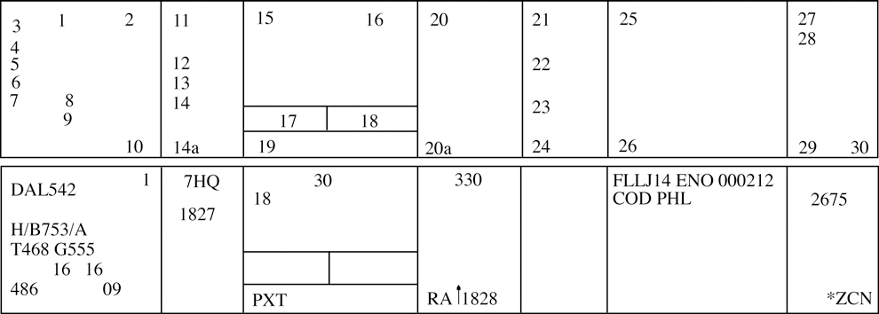
- Information recorded on the flight progress strips (FAA Forms 7230-19) must be entered in the correspondingly numbered spaces:
TBL 2-3-1 Block Information Recorded 1. Verification symbol if required. 2. Revision number.
DSR - Not used.3. Aircraft identification. 4. Number of aircraft if more than one, heavy aircraft indicator “H/” if appropriate, type of aircraft, and aircraft equipment suffix. 5. Filed true airspeed. 6. Sector number. 7. Computer identification number if required. 8. Estimated ground speed. 9. Revised ground speed or strip request (SR) originator. 10. Strip number.
DSR - Strip number/Revision number.11. Previous fix. 12. Estimated time over previous fix. 13. Revised estimated time over previous fix. 14. Actual time over previous fix, or actual departure time entered on first fix posting after departure. 14a. Plus time expressed in minutes from the previous fix to the posted fix. 15. Center-estimated time over fix (in hours and minutes), or clearance information for departing aircraft. 16. Arrows to indicate if aircraft is departing (↑) or arriving (↓). 17. Pilot-estimated time over fix. 18. Actual time over fix, time leaving holding fix, arrival time at nonapproach control airport, or symbol indicating cancellation of IFR flight plan for arriving aircraft, or departure time (actual or assumed). 19. Fix. For departing aircraft, add proposed departure time. 20. Altitude information (in hundreds of feet) or as noted below. NOTE: Altitude information may be written in thousands of feet provided the procedure is authorized by the facility manager, and is defined in a facility directive, i.e. FL 330 as 33, 5,000 feet as 5, and 2,800 as 2.8.
20a. OPTIONAL USE, when voice recorders are operational;
REQUIRED USE, when the voice recorders are not operating and strips are being use at the facility. This space is used to record reported RA events. The letters RA followed by a climb or descent arrow (if the climb or descent action is reported) and the time (hhmm) the event is reported.21. Next posted fix or coordination fix. 22. Pilot's estimated time over next fix. 23. Arrows to indicate north (↑), south (↓), east (→), or west (←) direction of flight if required. 24. Requested altitude. NOTE: Altitude information may be written in thousands of feet provided the procedure is authorized by the facility manager, and is defined in a facility directive, i.e., FL 330 as 33, 5,000 feet as 5, and 2,800 as 2.8.
25. Point of origin, route as required for control and data relay, and destination. 26. Pertinent remarks, minimum fuel, point out/radar vector/speed adjustment information or sector/position number (when applicable in accordance with para 2-2-1, Recording Information), or NRP. 27. Mode 3/A beacon code if applicable. 28. Miscellaneous control data (expected further clearance time, time cleared for approach, etc.). 29-30. Transfer of control data and coordination indicators. - Latitude/longitude coordinates may be used to define waypoints and may be substituted for nonadapted NAVAIDs in space 25 of domestic en route flight progress strips provided it is necessary to accommodate a random RNAV or GNSS route request.
- Facility air traffic managers may authorize the optional use of spaces 13, 14, 14a, 22, 23, 24, and 28 for point out information, radar vector information, speed adjustment information, or transfer of control data.
2-3-3. OCEANIC DATA ENTRIES
- The ATOP system displays information on electronic flight progress strips and, in the event of a catastrophic system failure, will print flight progress strips with data in the corresponding numbered spaces:
- Indicators are available for:
- M - Mach Number Technique (MNT),
- R - Reduced MNT,
- D or 3 - Distance-based longitudinal separation using 50 NM (D) or 30 NM (3), and
- W - Reduced Vertical Separation Minimum (RVSM).
- Standard annotations and abbreviations for Field 22 may be specified by facility directives.
| Block | Information Recorded |
|---|---|
| 1. | Mode 3/A beacon code, if applicable. |
| 2. | Number of aircraft, if more than one, and type of aircraft. |
| 3. | Aircraft identification. |
| 4. | Reduced separation flags.
|
| 5. | Controlling sector number. |
| 6. | Filed airspeed or assigned Mach number/True airspeed. |
| 7. | Reported flight level. May contain an indicator for a flight that is climbing (↑) or descending (↓). Reports from Mode C, ADS or position reports are displayed in that order of preference. |
| 8. | Cleared flight level. May contain an indicator for a future conditional altitude ( * ) that cannot be displayed. |
| 9. | Requested flight level, if applicable. |
| 10. | Previously reported position. |
| Block | Information Recorded |
|---|---|
| 11. | Actual time over previously reported position. |
| 12. | Last reported position. |
| 13. | Actual time over last reported position. |
| 14. | Next reporting position. |
| 15. | In-conformance pilot's estimate or controller-accepted pilot's estimate for next reporting position. |
| 16. | Future reporting position(s). |
| 17. | System estimate for future reporting position(s). |
| 18. | Departure airport or point of origin. |
| 19. | Destination airport or filed point of flight termination. |
| 20. | Indicators. Indicators and toggles for displaying or suppressing the display of the route of flight (F), second flight profile (2), radar contact (A), annotations (&), degraded Required Navigation Performance (RNP, indicator R) and clearance restrictions (X). |
| 21. | Coordination indicator(s). |
| 22. | Annotations. |
| 23. | Clearance restrictions and conditions (may be multiple lines). |
| 24. | Strip number and total number of strips (printed strips only). |
2-3-4. TERMINAL DATA ENTRIES
-
Arrivals: Information recorded on the flight progress strips (FAA Forms 7230-7.1, 7230-7.2, and 7230-8) must be
entered in the correspondingly numbered spaces.
Facility managers can authorize omissions and/or optional use of spaces 2A, 8A, 8B, 9A, 9B, 9C, and 10-18, if no misunderstanding will result. These omissions and/or optional uses must be specified in a facility directive.
-
Departures: Information recorded on the flight progress strips (FAA Forms 7230-7.1, 7230-7.2, and 7230-8) shall be
entered in the correspondingly numbered spaces.
Facility managers can authorize omissions and/or optional use of spaces 2A, 8A, 8B, 9A, 9B, 9C, and 10-18, if no misunderstanding will result. These omissions and/or optional uses shall be specified in a facility directive.
-
Overflights: Information recorded on the flight progress strips (FAA Forms 7230-7.1, 7230-7.2, and 7230-8) shall
be entered in the correspondingly numbered spaces.
Facility managers can authorize omissions and/or optional use of spaces 2A, 8A, 8B, 9A, 9B, 9C, and 10-18, if no misunderstanding will result. These omissions and/or optional uses shall be specified in a facility directive.
-
Air traffic managers at automated terminal radar facilities may waive the requirement to use flight progress
strips provided:
- Backup systems such as multiple radar sites/systems are utilized.
-
Local procedures are documented in a facility directive. These procedures should include but not be limited
to:
- (a) Departure areas and/or procedures.
- (b) Arrival procedures.
- (c) Overflight handling procedures.
- (d) Transition from radar to nonradar.
- (e) Transition to or from ESL.
- No misunderstanding will occur as a result of no strip usage.
- Unused flight progress strips, facility developed forms and/or blank notepads shall be provided for controller use.
- Facilities shall revert to flight progress strip usage if backup systems referred to in subparagraph d1 are not available.
- Air traffic managers at FDIO locations may authorize reduced lateral spacing between fields so as to print all FDIO data to the left of the strip perforation. When using FAA Form 7230-7.2, all items will retain the same relationship to each other as they do when the full length strip (FAA Form 7230-7.1) is used.

| Block | Information Recorded |
|---|---|
| 1. | Aircraft identification. |
| 2. | Revision number (FDIO locations only). |
| 2a. | Strip request originator. (At FDIO locations this indicates the sector or position that requested a strip be printed.) |
| 3. | Number of aircraft if more than one, heavy aircraft indicator “H/” if appropriate, type of aircraft, and aircraft equipment suffix. |
| 4. | Computer identification number if required. |
| 5. | Secondary radar (beacon) code assigned. |
| 6. |
(FDIO Locations.) The previous fix will be printed. (Non-FDIO Locations.) Use of the inbound airway. This function is restricted to facilities where flight data is received via interphone when agreed upon by the center and terminal facilities. |
| 7. | Coordination fix. |
| 8. | Estimated time of arrival at the coordination fix or destination airport. |
| 8a. | OPTIONAL USE. |
| 8b. |
OPTIONAL USE, when voice recorders are operational; REQUIRED USE, when the voice recorders are not operating and strips are being used at the facility. This space is used to record reported RA events when the voice recorders are not operational and strips are being used at the facility. The letters RA followed by a climb or descent arrow (if the climb or descent action is reported) and the time (hhmm) the event is reported. |
| Block | Information Recorded |
|---|---|
| 9. |
Altitude (in hundreds of feet) and remarks.
NOTE: Altitude information may be written in thousands of feet provided the procedure is authorized by the facility manager, and is defined in a facility directive, i.e., FL 230 as 23, 5,000 feet as 5, and 2,800 as 2.8. |
| 9a. |
Minimum fuel, destination airport/point out/radar vector/speed adjustment information. Air traffic managers
may authorize in a facility directive the omission of any of these items,
except minimum fuel, if no misunderstanding will result.
NOTE: Authorized omissions and optional use of spaces must be specified in the facility directive concerning strip marking procedures. |
| 9b. | OPTIONAL USE. |
| 9c. | OPTIONAL USE. |
| 10-18 | Enter data as specified by a facility directive. Radar facility personnel need not enter data in these spaces except when nonradar procedures are used or when radio recording equipment is inoperative. |
| Block | Information Recorded |
|---|---|
| 1. | Aircraft identification. |
| 2. | Revision number (FDIO locations only). |
| 2a. | Strip request originator. (At FDIO locations this indicates the sector or position that requested a strip be printed.) |
| 3. | Number of aircraft if more than one, heavy aircraft indicator “H/” if appropriate, type of aircraft, and aircraft equipment suffix. |
| 4. | Computer identification number if required. |
| 5. | Secondary radar (beacon) code assigned. |
| 6. | Proposed departure time. |
| 7. |
Requested altitude.
NOTE: Altitude information may be written in thousands of feet provided the procedure is authorized by the facility manager, and is defined in a facility directive, i.e., FL 230 as 23, 5,000 feet as 5, and 2,800 as 2.8. |
| 8. | Departure airport. |
| 8a. | OPTIONAL USE. |
| 8b. |
OPTIONAL USE, when voice recorders are operational; REQUIRED USE, when the voice recorders are not operating and strips are being used at the facility. This space is used to record reported RA events when the voice recorders are not operational and strips are being used at the facility. The letters RA followed by a climb or descent arrow (if the climb or descent action is reported) and the time (hhmm) the event is reported. |
| Block | Information Recorded |
|---|---|
| 9. |
Computer-generated: Route, destination, and remarks. Manually enter altitude/altitude restrictions in
the order flown, if appropriate, and remarks. Hand-prepared: Clearance limit, route, altitude/altitude restrictions in the order flown, if appropriate, and remarks. NOTE: Altitude information may be written in thousands of feet provided the procedure is authorized by the facility manager, and is defined in a facility directive, i.e., FL 230 as 23, 5,000 feet as 5, and 2,800 as 2.8. |
| 9a. | OPTIONAL USE. |
| 9b. | OPTIONAL USE. |
| 9c. | OPTIONAL USE. |
| 10-18 | Enter data as specified by a facility directive. Radar facility personnel need not enter data in these spaces except when nonradar procedures are used or when radio recording equipment is inoperative. |
| Block | Information Recorded |
|---|---|
| 1. | Aircraft identification. |
| 2. | Revision number (FDIO locations only). |
| 2a. | Strip request originator. (At FDIO locations this indicates the sector or position that requested a strip be printed.) |
| 3. | Number of aircraft if more than one, heavy aircraft indicator “H/” if appropriate, type of aircraft, and aircraft equipment suffix. |
| 4. | Computer identification number if required. |
| 5. | Secondary radar (beacon) code assigned. |
| 6. | Proposed departure time. |
| 7. |
Overflight coordination indicator (FDIO locations only).
NOTE: The overflight coordination indicator identifies the facility to which flight data has been forwarded. |
| 8. | Estimated time of arrival at the coordination fix. |
| Block | Information Recorded |
|---|---|
| 8a. | OPTIONAL USE. |
| 8b. |
OPTIONAL USE, when voice recorders are operational; REQUIRED USE, when the voice recorders are not operating and strips are being used at the facility. This space is used to record reported RA events when the voice recorders are not operational and strips are being used at the facility. The letters RA followed by a climb or descent arrow (if the climb or descent action is reported) and the time (hhmm) the event is reported. |
| 9. |
Altitude and route of flight through the terminal area.
NOTE: Altitude information may be written in thousands of feet provided the procedure is authorized by the facility manager, and is defined in a facility directive, i.e., FL 230 as 23, 5,000 feet as 5, and 2,800 as 2.8. |
| 9a. | OPTIONAL USE. |
| 9b. | OPTIONAL USE. |
| 9c. | OPTIONAL USE. |
| 10-18 | Enter data as specified by a facility directive. |
NOTE: National standardization of items (10 through 18) is not practical because of regional and local variations in operating methods; e.g., single fix, multiple fix, radar, tower en route control, etc.
2-3-5. AIRCRAFT IDENTITY
Indicate aircraft identity by one of the following using combinations not to exceed seven alphanumeric characters:
- Civil aircraft, including the air carrier letter digit registration number which can include the letter “T” for air taxi, the letter “L” for MEDEVAC, or the 3-letter company designator specified in FAA Order JO 7340.2, Contractions, followed by the trip or flight number. Use the operating air carrier's company name in identifying equipment interchange flights.
- EXAMPLE
- “N12345.”
- “TN5552Q.”
- “AAl192.”
- “LN751B.”
- Military Aircraft.
- Prefixes indicating branch of service and/or type of mission followed by the last 5 digits of the serial number (the last 4 digits for CFC and CTG). (See TBL 2-3-6 and TBL 2-3-7.)
- Pronounceable words of 3, 4, 5, and 6 letters followed by a 4, 3, 2, or 1-digit number.
- EXAMPLE
- “SAMP Three One Six.”
- Assigned double-letter 2-digit flight number.
- Navy or Marine fleet and training command aircraft, one of the following:
- (a) The service prefix and 2 letters (use phonetic alphabet equivalent) followed by 2 or 3 digits.
- (b) The service prefix and a digit and a letter (use phonetic alphabet equivalent) followed by 2 or 3 digits.
- Aircraft carrying the President, Vice President, and/or their family members will use the identifiers in the following tables. See TBL 2-3-8 and TBL 2-3-9.
- Special-use. Approved special-use identifiers.
NOTE: The letter “L” is not to be used for air carrier/air taxi MEDEVAC aircraft.
| Prefix | Branch |
|---|---|
| A | U.S. Air Force |
| C | U.S. Coast Guard |
| G | Air or Army National Guard |
| R | U.S. Army |
| VM | U.S. Marine Corps |
| VV | U.S. Navy |
| CFC | Canadian Forces |
| CTG | Canadian Coast Guard |
| Prefix | Mission |
|---|---|
| E | Medical Air Evacuation |
| F | Flight Check |
| L | LOGAIR (USAF Contract) |
| RCH | AMC (Air Mobility Command) |
| S | Special Air Mission |
| Service | President | Family |
|---|---|---|
| Air Force | AF1 | EXEC1F |
| Marine | VM1 | EXEC1F |
| Navy | VV1 | EXEC1F |
| Army | RR1 | EXEC1F |
| Coast Guard | C1 | EXEC1F |
| Guard | G1 | EXEC1F |
| Commercial | EXEC1 | EXEC1F |
| Service | President | Family |
|---|---|---|
| Air Force | AF2 | EXEC2F |
| Marine | VM2 | EXEC2F |
| Navy | VV2 | EXEC2F |
| Army | RR2 | EXEC2F |
| Coast Guard | C1 | EXEC2F |
| Guard | G1 | EXEC2F |
| Commercial | EXEC2 | EXEC2F |
2-3-6. AIRCRAFT TYPE
Use the approved aircraft type designator, in accordance with FAA Order 7360.1, Aircraft Type Designators.
2-3-7. USAF/USN UNDERGRADUATE PILOTS
To identify aircraft piloted by solo USAF/USN undergraduate student pilots (who may occasionally request revised clearances because they normally are restricted to flight in VFR conditions), the aircraft identification in the flight plan shall include the letter “Z” as a suffix. Do not use this suffix, however, in ground-to-air communication.
NOTE: USAF solo students who have passed an instrument certification check may penetrate cloud layers in climb or descent only. Requests for revised clearances to avoid clouds in level flight can still be expected. This does not change the requirement to use the letter “Z” as a suffix to the aircraft identification.
- REFERENCE
- FAA Order JO 7110.65, Para 2-4-20, Aircraft Identification.
- FAA Order JO 7610.4, Chapter 12, Section 10, USAF Undergraduate Flying Training (UFT)/Pilot Instructor Training (PIT)/Introduction To Fighter Fundamentals.
2-3-8. AIRCRAFT EQUIPMENT SUFFIX
- The aircraft equipment suffix identifying communication, navigation and surveillance (CNS) capability is generated by automation using the equipment codes of the ICAO flight plan. To change a suffix, the CNS equipment codes must be modified, allowing automation to translate them into the proper suffix. If using unsupported automation platforms (OFDPS and FDP2000), verbally coordinate changes with adjacent supported facilities.
- ERAM and ATOP are best suited for making changes to the equipment codes in an ICAO flight plan. For FDIO entries, if uncertain of the proper format to correctly amend an equipment code, verbally coordinate the change with the appropriate en route facility.
NOTE: Directly changing the equipment suffix with a symbol preceded by a slant instead of amending the aircraft equipment codes may unintentionally alter or delete other equipment codes.
- For VFR operations, indicate the aircraft's transponder and navigation capabilities by adding the appropriate symbol, preceded by a slant (See TBL 2-3-10).
- GNSS-equipped aircraft:
- Have an equipment suffix of /G, /L, /S, or /V.
- May be determined by executing an ICAO flight plan readout and verifying a filed “G” in the ICAO equipment list.
- May be determined by verifying with the pilot that the aircraft is GNSS-equipped.
- When forwarding this information, state the aircraft type followed by the word “slant” and the appropriate phonetic letter equivalent of the suffix.
- EXAMPLE
- “Cessna Three-ten slant Tango.”
- “A-Ten slant November.”
- “F-Sixteen slant Papa.”
- “Seven-sixty-seven slant Golf.”
/H and /O are intended for ATC use only. These suffixes are not published in the Aeronautical Information Manual.
| Separation Standard | Navigation Capability | Transponder Capability | Suffix |
|---|---|---|---|
| RVSM | Any | Failed transponder | /H |
| Any | Failed Mode C capability | /O | |
| No RNAV, No GNSS | Transponder with Mode C | /W | |
| RNAV, No GNSS | Transponder with Mode C | /Z | |
| GNSS | Transponder with Mode C | /L | |
| Non-RVSM | No DME | No transponder | /X |
| Transponder, no Mode C | /T | ||
| Transponder with Mode C | /U | ||
| DME | No transponder | /D | |
| Transponder, no Mode C | /B | ||
| Transponder with Mode C | /A | ||
| TACAN | No transponder | /M | |
| Transponder, no Mode C | /N | ||
| Transponder with Mode C | /P | ||
| RNAV, No GNSS | No transponder | /Y | |
| Transponder, no Mode C | /C | ||
| Transponder with Mode C | /I | ||
| GNSS | No transponder | /V | |
| Transponder, no Mode C | /S | ||
| Transponder with Mode C | /G | ||
2-3-9. CLEARANCE STATUS
Use an appropriate clearance symbol followed by a dash (-) and other pertinent information to clearly show the clearance status of an aircraft. To indicate delay status use:
- The symbol “H” at the clearance limit when holding instructions have been included in the aircraft's original clearance. Show detailed holding information following the dash when holding differs from the established pattern for the fix; i.e., turns, leg lengths, etc.
- The symbols “F” or “O” to indicate the clearance limit when a delay is not anticipated.
2-3-10. CONTROL SYMBOLOGY
Use authorized control and clearance symbols or abbreviations for recording clearances, reports, and instructions. Control status of aircraft must always be current. You may use:
- Plain language markings when it will aid in understanding information.
- Locally approved identifiers. Use these only within your facility and not on teletypewriter or interphone circuits.
- Plain sheets of paper or locally prepared forms to record information when flight progress strips are not used. (See TBL 2-3-11 and TBL 2-3-12.)
- Control Information Symbols. (See FIG 2-3-7 and FIG 2-3-8.)
| Abbreviation | Meaning |
|---|---|
| A | Cleared to airport (point of intended landing) |
| B | Center clearance delivered |
| C | ATC clears (when clearance relayed through non-ATC facility) |
| CAF | Cleared as filed |
| D | Cleared to depart from the fix |
| F | Cleared to the fix |
| H | Cleared to hold and instructions issued |
| L | Cleared to land |
| N | Clearance not delivered |
| O | Cleared to the outer marker |
| PD | Cleared to climb/descend at pilot's discretion |
| Q | Cleared to fly specified sectors of a NAVAID defined in terms of courses, bearings, radials or quadrants within a designated radius. |
| T | Cleared through (for landing and takeoff through intermediate point) |
| V | Cleared over the fix |
| X | Cleared to cross (airway, route, radial) at (point) |
| Z | Tower jurisdiction |
| Abbreviations | Meaning |
|---|---|
| BC | Back course approach |
| CT | Contact approach |
| FA | Final approach |
| FMS | Flight management system approach |
| GPS | GPS approach |
| I | Initial approach |
| ILS | ILS approach |
| MA | Missed approach |
| NDB | Nondirectional radio beacon approach |
| OTP | VFR conditions-on-top |
| PA | Precision approach |
| PT | Procedure turn |
| RA | Resolution advisory (Pilot reported TCAS event) |
| RH | Runway heading |
| RNAV | Area navigation approach |
| RP | Report immediately upon passing (fix/altitude) |
| RX | Report crossing |
| SA | Surveillance approach |
| SI | Straight-in approach |
| TA | TACAN approach |
| TL | Turn left |
| TR | Turn right |
| VA | Visual approach |
| VR | VOR approach |
| Symbols | Meaning |
|---|---|
| T → ( ) | Depart (direction, if specified) |
| ↑ | Climb and maintain |
| ↓ | Descend and maintain |
| → | Cruise |
| @ | At |
| X | Cross |
| ―M→ | Maintain |
| ⇁ | Join or intercept airway/jet route/track or course |
| While in controlled airspace | |
| Δ | While in control area |
| ↘︎Δ | Enter control area |
| ↗︎Δ | Out of control area |
|
NW◯↘︎ ◯↗︎ NE ◯→E |
Cleared to enter, depart or through surface area. Indicated direction of flight by arrow and appropriate compass letter. Maintain Special VFR conditions (altitude, if appropriate) while in surface area. |
| 250 K | Aircraft requested to adjust speed to 250 knots. |
| -20 K | Aircraft requested to reduce speed 20 knots. |
| +30 K | Aircraft requested to increase speed 30 knots. |
| ◯W | Local Special VFR operations in the vicinity of (name) airport are authorized until (time). Maintain Special VFR conditions (altitude if appropriate). |
| < | Before |
| > | After or Past |
| 170 | Inappropriate altitude/flight level for direction of flight. (Underline assigned altitude/flight level in red). |
| / | Until |
| ( ) | Alternate instructions |
| Restriction | Restriction |
| ↧ | At or Below |
| ↥ | At or Above |
| - (Dash) | From-to (route, time, etc.) |
| (Alt)B(Alt) | Indicates a block altitude assignment. Altitudes area inclusive, and the first altitude shall be lower than the second. Example: 310B370 |
| v < | Clearance void if aircraft not off ground by (time) |
| NOTE: The absence of an airway route number between two fixes in the route of flight indicates "direct"; no symbol or abbreviation is required. | |
| CL | Pilot canceled flight plan |
| ✓ | EN ROUTE: Aircraft has reported at assigned altitude. Example: 80✓ |
| ✓ | TERMINAL/FSS: Information forwarded (indicated information forwarded as required) |
| ◯ | EN ROUTE: Information or revised information forwarded. (Circle, in red, inappropriate altitude/flight level for direction of flight or other control information when coordinated. Also circle, in red, the time (minutes and altitude) when a flight plan or estimate is forwarded. Use method in both inter-center and intra-center coordination. |
| ◯50 | Other than assigned altitude reported (circle reported altitude) |
| 10H6 | DME holding (use with mileages)(Upper figure indicates distance from station to DME fix, lower figure indicates length of holding pattern.) In this example, the DME fix is 10 miles out with a 6 mile pattern indicated. |
| (mi.)(dir.)⁀ | DME arc of VORTAC, TACAN, or MLS. |
| C―(freq.) | Contact (facility) on (freq.), (time, fix, or altitude if appropriate). Insert frequency only when it is other than standard. |
| R | Radar Contact |
| R | EN ROUTE: Requested altitude (preceding altitude information) |
| R╱ | Radar service terminated |
| R✕ | Radar contact lost |
| RV | Radar vector |
| RV✕ | Pilot resumed own navigation |
| ◯R | Radar handoff (circle symbol when handoff completed) |
| E | EMERGENCY |
| W | WARNING |
| P | Point out initiated. Indicate the appropriate facility, sector or position. Example: PZFW. |
| FUEL | Minimum fuel |
| NOTE: The absence of an airway route number between two fixes in the route of flight indicates "direct"; no symbol or abbreviation is required. | |
Section 4. Radio and Interphone Communications
2-4-1. RADIO COMMUNICATIONS
Use radio frequencies for the special purposes for which they are intended. A single frequency may be used for more than one function except as follows:
TERMINAL. When combining positions in the tower, do not use ground control frequency for airborne communications.
NOTE: Due to the limited number of frequencies assigned to towers for the ground control function, it is very likely that airborne use of a ground control frequency could cause interference to other towers or interference to your aircraft from another tower. When combining these functions, it is recommended combining them on local control. The ATIS may be used to specify the desired frequency.
2-4-2. MONITORING
Monitor interphones and assigned radio frequencies continuously.
NOTE: Although all FAA facilities, including RAPCONs and RATCFs, are required to monitor all assigned frequencies continuously, USAF facilities may not monitor all unpublished discrete frequencies.
2-4-3. PILOT ACKNOWLEDGMENT/READ BACK
Ensure pilots acknowledge all Air Traffic Clearances and ATC Instructions. When a pilot reads back an Air Traffic Clearance or ATC Instruction:
- Ensure that items read back are correct.
- Ensure the read back of hold short instructions, whether a part of taxi instructions or a LAHSO clearance.
- Ensure pilots use call signs and/or registration numbers in any read back acknowledging an Air Traffic Clearance or ATC Instruction.
- NOTE:
- 1. ATC Clearance/Instruction Read Back guidance for pilots in the AIM states:
- Although pilots should read back the “numbers,” unless otherwise required by procedure or controller request, pilots may acknowledge clearances, control instructions, or other information by using “Wilco,” “Roger,” “Affirmative,” or other words or remarks with their aircraft identification.
- Altitudes contained in charted procedures, such as departure procedures, instrument approaches, etc., need not be read back unless they are specifically stated by the controller.
- Initial read back of a taxi, departure or landing clearance should include the runway assignment, including left, right, center, etc. if applicable.
- 2. Until a pilot acknowledges a controller's clearance or instruction, a controller cannot know if a pilot will comply with the clearance or remain as previously cleared.
- EXAMPLE
- “Climbing to Flight Level three three zero, United Twelve” or “November Five Charlie Tango, roger, cleared to land runway four left.”
- REFERENCE
- P/CG Term - Air Traffic Clearance.
- P/CG Term - ATC Instructions.
- JO 7110.65, 3-7-2, Taxi and Ground Movement Operations.
- JO 7110.65, 10-4-4, Communications Failure.
- AIM Para 4-2-3, Contact Procedures..
- AIM Para 4-4-7, Pilot Responsibility upon Clearance Issuance.
- AIM Para 6-4-1, Two-way Radio Communications Failure.
- Federal Register, April 1, 1999 14 CFR Part 91 Pilot Responsibility for Compliance with ATC Clearances and Instructions.
2-4-4. AUTHORIZED INTERRUPTIONS
As necessary, authorize a pilot to interrupt his/her communications guard.
NOTE: Some users have adopted procedures to ensure uninterrupted receiving capability with ATC when a pilot with only one operative communications radio must interrupt his/her communications guard because of a safety related problem requiring airborne communications with his/her company. In this event, pilots will request approval to abandon guard on the assigned ATC frequency for a mutually agreeable time period. Additionally, they will inform controllers of the NAVAID voice facility and the company frequency they will monitor.
2-4-5. AUTHORIZED TRANSMISSIONS
Transmit only those messages necessary for air traffic control or otherwise contributing to air safety.
- REFERENCE
- FAA Order JO 7210.3, Para 3-2-2, Authorized Messages Not Directly Associated with Air Traffic Services.
2-4-6. FALSE OR DECEPTIVE COMMUNICATIONS
Take action to detect, prevent, and report false, deceptive, or phantom controller communications to an aircraft or controller. The following must be accomplished when false or deceptive communications occur:
- Correct false information.
- Broadcast an alert to aircraft operating on all frequencies within the area where deceptive or phantom transmissions have been received.
- EXAMPLE
- “Attention all aircraft. False ATC instructions have been received in the area of Long Beach Airport. Exercise extreme caution on all frequencies and verify instructions.”
- Collect pertinent information regarding the incident.
- Notify the operations supervisor of the false, deceptive, or phantom transmission and report all relevant information pertaining to the incident.
2-4-7. AUTHORIZED RELAYS
- Relay operational information to aircraft or aircraft operators as necessary. Do not agree to handle such messages on a regular basis. Give the source of any such message you relay.
- Relay official FAA messages as required.
NOTE: The FAA Administrator and Deputy Administrator will sometimes use code phrases to identify themselves in air-to-ground communications as follows:
- Administrator: “SAFEAIR ONE.”
- Deputy Administrator: “SAFEAIR TWO.”
- EXAMPLE
- “Miami Center, Jetstar One, this is SAFEAIR ONE, (message).”
- Relay operational information to military aircraft operating on, or planning to operate on IRs.
2-4-8. RADIO MESSAGE FORMAT
Use the following format for radio communications with an aircraft:
- Sector/position on initial radio contact:
- Identification of aircraft.
- Identification of ATC unit.
- Message (if any).
- The word “over” if required.
- Subsequent radio transmissions from the same sector/position must use the same format, except the identification of the ATC unit may be omitted.
TERMINAL. You may omit aircraft identification after initial contact when conducting the final portion of a radar approach.
2-4-9. ABBREVIATED TRANSMISSIONS
Transmissions may be abbreviated as follows:
- Use the identification prefix and the last 3 digits or letters of the aircraft identification after communications have been established with a U.S. civil aircraft using the aircraft registration as identification.
- Do not abbreviate:
- Similar sounding aircraft identifications.
- Aircraft call signs, including:
- (a) Aircraft having an International Civil Aviation Organization three letter designator (ICAO 3LD) and other aircraft with an FAA authorized call sign (U.S. special or local).
- (b) Aircraft with a military call sign.
- Foreign aircraft using the foreign civil registration number as identification.
- REFERENCE
- FAA Order JO 7110.65, Para 2-4-15, Emphasis for Clarity.
- FAA Order JO 7110.65, Para 2-4-20, Aircraft Identification.
- FAA Order JO 7610.12, Assignment and Authorization of Call Sign Designators and Associated Telephonies.
- Omit the facility identification after communication has been established.
- Transmit the message immediately after the callup (without waiting for the aircraft's reply) when the message is short and receipt is generally assured.
- Omit the word “over” if the message obviously requires a reply.
2-4-10. INTERPHONE TRANSMISSION PRIORITIES
Give priority to interphone transmissions as follows:
- First priority. Emergency messages including essential information on aircraft accidents or suspected accidents. After an actual emergency has passed, give a lower priority to messages relating to that accident.
- Second priority. Clearances and control instructions.
- Third priority. Movement and control messages using the following order of preference when possible:
- Progress reports.
- Departure or arrival reports.
- Flight plans.
- Fourth priority. Movement messages on VFR aircraft.
2-4-11. PRIORITY INTERRUPTION
Use the words “emergency” or “control” for interrupting lower priority messages when you have an emergency or control message to transmit.
2-4-12. INTERPHONE MESSAGE FORMAT
Use the following format for interphone intra/interfacility communications:
- Both the caller and receiver identify their facility and/or position in a manner that ensures they will not be confused with another position.
NOTE: Other means of identifying a position, such as substituting departure or arrival gate/fix names for position identification, may be used. However, it must be operationally beneficial, and the procedure fully covered in a letter of agreement or a facility directive, as appropriate.
- EXAMPLE
- Caller: “Albuquerque Center Sixty Three, Amarillo Departure.”
- Receiver: “Albuquerque Center.”
- Between two facilities which utilize numeric position identification, the caller must identify both facility and position.
- EXAMPLE
- Caller: “Albuquerque Sixty Three, Fort Worth Eighty Two.”
- Caller states the type of coordination to be accomplished when advantageous. For example, handoff or APREQ.
- The caller states the message.
- The receiver states the response to the caller's message followed by the receiver's operating initials.
- The caller states his or her operating initials.
- EXAMPLE
- 1. Caller: “Denver High, R Twenty-five.”
- Receiver: “Denver High.”
- Caller: “Request direct Denver for Northwest Three Twenty-eight.”
- Receiver: “Northwest Three Twenty-eight direct Denver approved. H.F.”
- Caller: “G.M.”
- 2. Receiver: “Denver High, Go ahead override.”
- Caller: “R Twenty-five, Request direct Denver for Northwest Three Twenty-eight.”
- Receiver: “Northwest Three Twenty-eight direct Denver approved. H.F.”
- Caller: “G.M.”
- 3. Caller: (“Bolos” is a departure gate in Houston ARTCC's Sabine sector)-“Bolos, Houston local.”
- Receiver: “Bolos.”
- Caller: “Request Flight Level three five zero for American Twenty-five.”
- Receiver: “American Twenty-five Flight Level three five zero approved, A.C.”
- Caller: “G.M.”
- 4. Caller: “Sector Twelve, Ontario Approach, APREQ.”
- Receiver: “Sector Twelve.”
- Caller: “Cactus Five forty-two heading one three zero and climbing to one four thousand.”
- Receiver: “Cactus Five forty-two heading one three zero and climbing to one four thousand approved. B.N.”
- Caller: “A.M.”
- 5. Caller: “Zanesville, Columbus, seventy-three line, handoff.”
- Receiver: “Zanesville.”
- Caller: “Five miles east of Appleton VOR, United Three Sixty-six.”
- Receiver: “United Three Sixty-six, radar contact, A.Z.” Caller: “M.E.”
- Identify the interphone voice line on which the call is being made when two or more such lines are collocated at the receiving operating position.
- EXAMPLE
- “Washington Center, Washington Approach on the Fifty Seven line.”
- “Chicago Center, O'Hare Tower handoff on the Departure West line.”
- TERMINAL. The provisions of sub paras a, b, c, e, f, g, and para 2-4-13, Interphone Message Termination, may be omitted provided:
- Abbreviated standard coordination procedures are contained in a facility directive describing the specific conditions and positions that may utilize an abbreviated interphone message format; and
- There will be no possibility of misunderstanding which positions are using the abbreviated procedures.
2-4-13. INTERPHONE MESSAGE TERMINATION
Terminate interphone messages with your operating initials.
2-4-14. WORDS AND PHRASES
- Use the words or phrases in radiotelephone and interphone communication as contained in the P/CG or, within areas where Controller Pilot Data Link Communications (CPDLC) is in use, the phraseology contained in the applicable CPDLC message set.
- The word super must be used as part of the identification in all communications with or about super aircraft.
- The word heavy must be used as part of the identification in all communications with or about heavy aircraft.
- EN ROUTE. The use of the words super or heavy may be omitted except as follows:
- In communications with a terminal facility about super or heavy aircraft operations.
- In communications with or about super or heavy aircraft with regard to an airport where the en route center is providing approach control service.
- In communications with or about super or heavy aircraft when the separation from a following aircraft may become less than 5 miles by approved procedure.
- When issuing traffic advisories.
- EXAMPLE
- “United Fifty-Eight Heavy.”
NOTE: Most airlines will use the word “super” or “heavy” following the company prefix and flight number when establishing communications or when changing frequencies within a terminal facility's area.
- When in radio communications with “Air Force One” or “Air Force Two,” do not add the heavy designator to the call sign. State only the call sign “Air Force One/Two” regardless of the type aircraft.
2-4-15. EMPHASIS FOR CLARITY
Emphasize appropriate digits, letters, or similar sounding words to aid in distinguishing between similar sounding aircraft identifications. Additionally:
- Treat aircraft with similar sounding aircraft identifications by emphasizing appropriate digits, letters, or similar sounding words to aid in distinguishing between similar sounding aircraft identifications. Do not abbreviate similar sounding aircraft identifications.
- Treat aircraft with similar sounding call signs by restating the call sign after the flight number.
- EXAMPLE
- “United Thirty-one United.”
- “American Thirty-one American.”
NOTE: Similar sounding call signs procedures may apply to ICAO 3LD U.S. special, local, or military call sign.
- Notify each pilot concerned when communicating with aircraft having similar sounding identifications.
- EXAMPLE
- “United Thirty-one United, Miami Center, U.S. Air Thirty-one is also on this frequency, acknowledge.”
- “U.S. Air Thirty-one U.S. Air, Miami Center, United Thirty-one is also on this frequency, acknowledge.”
- REFERENCE
- FAA Order JO 7110.65, Para 2-4-20, Aircraft Identification.
- FAA Order JO 7210.3, Para 2-1-14, Aircraft Identification Problems.
- Notify the operations supervisor-in-charge of any duplicate call signs or phonetically similar-sounding call signs when the aircraft are operating simultaneously within the same sector.
- REFERENCE
- FAA Order JO 7210.3, Para 2-1-14, Aircraft Identification Problems.
2-4-16. ICAO PHONETICS
Use the ICAO pronunciation of numbers and individual letters. (See the ICAO radiotelephony alphabet and pronunciation in TBL 2-4-1.)
| Character | Word | Pronunciation |
|---|---|---|
| 0 | Zero | ZE-RO |
| 1 | One | WUN |
| 2 | Two | TOO |
| 3 | Three | TREE |
| 4 | Four | FOW-ER |
| 5 | Five | FIFE |
| 6 | Six | SIX |
| 7 | Seven | SEV-EN |
| 8 | Eight | AIT |
| 9 | Nine | NIN-ER |
| A | Alfa | ALFAH |
| B | Bravo | BRAHVOH |
| C | Charlie | CHARLEE |
| D | Delta | DELLTAH |
| E | Echo | ECKOH |
| F | Foxtrot | FOKSTROT |
| G | Golf | GOLF |
| H | Hotel | HOHTELL |
| I | India | INDEE AH |
| J | Juliet | JEWLEE ETT |
| K | Kilo | KEYLOH |
| L | Lima | LEEMAH |
| M | Mike | MIKE |
| N | November | NOVEMBER |
| O | Oscar | OSSCAH |
| P | Papa | PAHPAH |
| Q | Quebec | KEHBECK |
| R | Romeo | ROWME OH |
| S | Sierra | SEEAIRAH |
| T | Tango | TANGGO |
| U | Uniform | YOUNEE FORM |
| V | Victor | VIKTAH |
| W | Whiskey | WISSKEY |
| X | X-ray | ECKSRAY |
| Y | Yankee | YANGKEY |
| Z | Zulu | ZOOLOO |
2-4-17. NUMBERS USAGE
interpretation 2State numbers as follows:
- Serial numbers. The separate digits.
- EXAMPLE
Number Statement 11,495 “One one four niner five.” 20,069 “Two zero zero six niner.”
- Altitudes or flight levels:
- Altitudes. Pronounce each digit in the number of hundreds or thousands followed by the word “hundred” or “thousand” as appropriate.
- EXAMPLE
Number Statement 10,000 “One zero thousand.” 11,000 “One one thousand.” 17,900 “One seven thousand niner hundred.”
NOTE: Altitudes may be restated in group form for added clarity if the controller chooses.
- EXAMPLE
Number Statement 10,000 “Ten thousand.” 11,000 “Eleven thousand.” 17,900 “Seventeen thousand niner hundred.”
- Flight levels. The words “flight level” followed by the separate digits of the flight level.
- EXAMPLE
Flight Level Statement 180 “Flight level one eight zero.” 275 “Flight level two seven five.”
- MDA/DH Altitudes. The separate digits of the MDA/DH altitude.
- EXAMPLE
MDA/DH Altitude Statement 1,320 “Minimum descent altitude, one three two zero.” 486 “Decision height, four eight six.”
- Altitudes. Pronounce each digit in the number of hundreds or thousands followed by the word “hundred” or “thousand” as appropriate.
- Time:
- General time information. The four separate digits of the hour and minute/s in terms of UTC.
- EXAMPLE
UTC Time (12 hour) Statement 0715 1:15 a.m. CST “Zero seven one five.” 1915 1:15 p.m. CST “One niner one five.”
- Upon request. The four separate digits of the hours and minute/s in terms of UTC followed by the local standard time equivalent; or the local time equivalent only. Local time may be based on the 24-hour clock system, and the word “local” or the time zone equivalent must be stated when other than UTC is referenced. The term “ZULU” may be used to denote UTC.
- EXAMPLE
UTC Time (24 hour) Time (12 hour) Statement 2230 1430 PST 2:30 p.m. “Two two three zero, one four three zero Pacific or Local.” or “Two-thirty P-M.”
- Time check. The word “time” followed by the four separate digits of the hour and minutes, and nearest quarter minute. Fractions of a quarter minute less than eight seconds are stated as the preceding quarter minute; fractions of a quarter minute of eight seconds or more are stated as succeeding quarter minute.
- EXAMPLE
Time Statement 1415:06 “Time, one four one five.” 1415:10 “Time, one four one five and one-quarter.”
- Abbreviated time. The separate digits of the minutes only.
- EXAMPLE
Time Statement 1415 “One five.” 1420 “Two zero.”
- General time information. The four separate digits of the hour and minute/s in terms of UTC.
- Field elevation. The words “field elevation” followed by the separate digits of the elevation.
- EXAMPLE
Elevation Statement 17 feet “Field elevation, one seven.” 817 feet “Field elevation, eight one seven.” 2,817 feet “Field elevation, two eight one seven.”
- The number “0” as “zero” except where it is used in approved “group form” for authorized aircraft call signs, and in stating altitudes.
- EXAMPLE
As Zero As Group “Field elevation one six zero.”
“Heading three zero zero.”
“One zero thousand five hundred.”“Western five thirty.”
“EMAIR One Ten.”
“Ten thousand five hundred.”
- Altimeter setting. The word “altimeter” followed by the separate digits of the altimeter setting.
- EXAMPLE
Setting Statement 30.01 “Altimeter, three zero zero one.”
- Surface wind. The word “wind” followed by the separate digits of the indicated wind direction to the nearest 10-degree multiple, the word “at” and the separate digits of the indicated velocity in knots, to include any gusts.
- EXAMPLE
- “Wind zero three zero at two five.”
- “Wind two seven zero at one five gusts three five.”
- Heading. The word “heading” followed by the three separate digits of the number of degrees, omitting the word “degrees.” Use heading 360 degrees to indicate a north heading.
- EXAMPLE
Heading Statement 5 degrees “Heading zero zero five.” 30 degrees “Heading zero three zero.” 360 degrees “Heading three six zero.”
- Radar beacon codes. The separate digits of the 4-digit code.
- EXAMPLE
Code Statement 1000 “One zero zero zero.” 2100 “Two one zero zero.”
- Runways. The word “runway,” followed by the separate digits of the runway designation. For a parallel runway, state the word “left,” “right,” or “center” if the letter “L,” “R,” or “C” is included in the designation.
- EXAMPLE
Designation Statement 3 “Runway Three.” 8L “Runway Eight Left.” 27R “Runway Two Seven Right.”
- Frequencies.
- The separate digits of the frequency, inserting the word “point” where the decimal point occurs.
- (a) Omit digits after the second digit to the right of the decimal point.
- (b) When the frequency is in the L/MF band, include the word “kilohertz.”
- EXAMPLE
Frequency Statement 126.55 MHz “One two six point five five.” 369.0 MHz “Three six niner point zero.” 121.5 MHz “One two one point five.” 135.275 MHz “One three five point two seven.” 302 kHz “Three zero two kilohertz.”
- USAF/USN. Local channelization numbers may be used in lieu of frequencies for locally based aircraft when local procedures are established to ensure that local aircraft and ATC facilities use the same channelization.
- EXAMPLE
Frequency Statement 275.8 MHz “Local channel one six.”
- Issue TACAN frequencies by stating the assigned two or three-digit channel number.
- The separate digits of the frequency, inserting the word “point” where the decimal point occurs.
- Speeds.
- The separate digits of the speed followed by “knots” except as required by para 5-7-2, Methods.
- EXAMPLE
Speed Statement 250 “Two five zero knots.” 190 “One niner zero knots.”
- The separate digits of the Mach number preceded by “Mach.”
- EXAMPLE
Mach Number Statement 1.5 “Mach one point five.” 0.64 “Mach point six four.” 0.7 “Mach point seven.”
- The separate digits of the speed followed by “knots” except as required by para 5-7-2, Methods.
- Miles. The separate digits of the mileage followed by the word “mile.”
- EXAMPLE
- “Three zero mile arc east of Nottingham.”
- “Traffic, one o'clock, two five miles, northbound, D-C Eight, flight level two seven zero.”
2-4-18. NUMBER CLARIFICATION
- If deemed necessary for clarity, and after stating numbers as specified in para 2-4-17, Numbers Usage, controllers may restate numbers using either group or single-digit form.
- EXAMPLE
- “One Seven Thousand, Seventeen Thousand.” “Altimeter Two Niner Niner Two, Twenty Nine Ninety Two.”
- “One Two Six Point Five Five, One Twenty Six Point Fifty Five.”
2-4-19. FACILITY IDENTIFICATION
Identify facilities as follows:
- Airport traffic control towers. State the name of the facility followed by the word “tower.” Where military and civil airports are located in the same general area and have similar names, state the name of the military service followed by the name of the military facility and the word “tower.”
- EXAMPLE
- “Columbus Tower.” “Barksdale Tower.”
- “Navy Jacksonville Tower.”
- Air route traffic control centers. State the name of the facility followed by the word “center.”
- Approach control facilities, including RAPCONs, RATCFs, and ARACs. State the name of the facility followed by the word “approach.” Where military and civil facilities are located in the same general area and have similar names, state the name of the military service followed by the name of the military facility and the word “approach.”
- EXAMPLE
- “Denver Approach.”
- “Griffiss Approach.”
- “Navy Jacksonville Approach.”
- Functions within a terminal facility. State the name of the facility followed by the name of the function.
- EXAMPLE
- “Boston Departure.”
- “La Guardia Clearance Delivery.” “O'Hare Ground.”
- When calling or replying on an interphone line which connects only two non-VSCS equipped facilities, you may omit the facility name.
- EXAMPLE
- “Bradford High, Handoff.”
- Flight service stations. State the name of the station followed by the word “radio.”
- EXAMPLE
- "Leesburg Radio.”
- Radar facilities having ASR or PAR but not providing approach control service. State the name of the facility, followed by the letters “G-C-A.”
- EXAMPLE
- “Corpus Christi G-C-A.”
- “Davison G-C-A.”
2-4-20. AIRCRAFT IDENTIFICATION
Use the full identification in reply to aircraft with similar sounding identifications. For other aircraft, the same identification may be used in reply that the pilot used in his/her initial callup except use the correct identification after communications have been established. Identify aircraft as follows:
- U.S. registry aircraft. State one of the following:
- REFERENCE
- FAA Order JO 7110.65, Para 2-4-8, Radio Message Format.
- FAA Order JO 7110.65, Para 2-4-9, Abbreviated Transmissions.
- FAA Order JO 7110.65, Para 2-4-15, Emphasis for Clarity.
- FAA Order JO 7110.65, Para 2-4-17, Numbers Usage.
- Civil. State the prefix “November” when establishing initial communications with U.S. registered aircraft
followed by the ICAO phonetic pronunciation of the numbers/letters of the aircraft registration. The
controller may state the aircraft type, the model, the manufacturer's name, followed by the ICAO phonetic
pronunciation of the numbers/letters of the aircraft registration if used by the pilot on the initial or
subsequent call.
- EXAMPLE
- Air traffic controller's initiated call:
“November One Two Three Four Golf.”
“November One Two Three Four.” - Responding to pilot's initial or subsequent call:
“Jet Commander One Two Three Four Papa.”
“Bonanza One Two Three Four Tango.”
“Sikorsky Six Three Eight Mike Foxtrot.”
NOTE: If aircraft identification becomes a problem when the procedures specified above are used, see paragraph 2-4-15, Emphasis for Clarity.
- Aircraft having an ICAO 3LD and other FAA authorized call sign (U.S. special or local). State the call sign
followed by the flight number in group form.
NOTE: “Group form” is the pronunciation of a series of numbers as the whole number, or pairs of numbers they represent rather than pronouncing each separate digit. The use of group form may, however, be negated by four-digit identifiers or the placement of zeros in the identifier.
- EXAMPLE
- “American Fifty-Two.”
- “Delta One Hundred.”
- “Eastern Metro One Ten.”
- “General Motors Thirty Fifteen.”
- “United One Zero One.”
- “Delta Zero One Zero.”
- “TWA Ten Zero Four.”
NOTE: For clarity, aircraft having an ICAO 3LD and other FAA authorized call sign may be pronounced using single digits if necessary.
- EXAMPLE
- “United Five One Seven.”
- “United Five Seven Zero.”
NOTE: For procedures that address similar sounding call signs, see paragraph 2-4-15, Emphasis for Clarity.
- REFERENCE
- Air taxi and commercial operators not having FAA authorized call signs. State the prefix “TANGO” on initial
contact, if used by the pilot, followed by the registration number. The prefix may be dropped in subsequent
communications.
- EXAMPLE
- “Tango Mooney Five Five Five Two Quebec.”
- “Tango November One Two Three Four.”
- Air carrier/taxi ambulance. State the prefix “MEDEVAC” if used by the pilot, followed by the call sign and
flight number in group form.
- EXAMPLE
- “MEDEVAC Delta Fifty-One.”
- Civilian air ambulance. State the word “MEDEVAC” followed by the numbers/letters of the registration number.
- EXAMPLE
- “MEDEVAC Two Six Four Six.”
- U.S. military. State one of the following:
- (a) The service name, followed by the word “copter,” when appropriate, and the last 5 digits of the serial
number.
- EXAMPLE
- “Navy Five Six Seven One Three.”
- “Coast Guard Six One Three Two Seven.”
- “Air Guard One Three Five Eight Six.”
- “Army Copter Three Two One Seven Six.”
NOTE: If aircraft identification becomes a problem, the procedures reflected in FAA Order JO 7210.3, Facility Operation and Administration, para 2-1-14, Aircraft Identification Problems, will apply.
- (b) Special military operations. State one of the following followed by the last 5 digits of the serial number:
- (c) Air evacuation flights. “AIR EVAC,” “MARINE AIR EVAC,” or “NAVY AIR EVAC.”
- EXAMPLE
- “Air Evac One Seven Six Five Two.”
- (d) Rescue flights. (Service name) “RESCUE.”
- EXAMPLE
- “Air Force Rescue Six One Five Seven Niner.”
- (e) Air Mobility Command. “REACH.”
- EXAMPLE
- “Reach Seven Eight Five Six Two.”
- (f) Special Air Mission. “SAM.”
- EXAMPLE
- “Sam Niner One Five Six Two.”
- (g) USAF Contract Aircraft “LOGAIR.”
- EXAMPLE
- “Logair Seven Five Eight Two Six.”
- (h) Military tactical and training:
- (1) U.S. Air Force, Air National Guard, Military District of Washington priority aircraft, and USAF
civil disturbance aircraft. Pronounceable words of 3 to 6 letters followed by a 1 to 5 digit number.
- EXAMPLE
- “Paul Two Zero.”
- “Pat One Five Seven.”
- “Gaydog Four.”
NOTE: When the “Z” suffix described in para 2-3-7, USAF/USN Undergraduate Pilots, is added to identify aircraft piloted by USAF undergraduate pilots, the call sign will be limited to a combination of six characters.
- (2) Navy or Marine fleet and training command aircraft. The service name and 2 letters, or a digit and a
letter (use letter phonetic equivalents), followed by 2 or 3 digits.
- EXAMPLE
- “Navy Golf Alfa Two One.”
- “Marine Four Charlie Two Three Six.”
- (1) U.S. Air Force, Air National Guard, Military District of Washington priority aircraft, and USAF
civil disturbance aircraft. Pronounceable words of 3 to 6 letters followed by a 1 to 5 digit number.
- (a) The service name, followed by the word “copter,” when appropriate, and the last 5 digits of the serial
number.
- Presidential aircraft and Presidential family aircraft:
- (a) When the President is aboard a military aircraft, state the name of the military service, followed by the word “One.”
- EXAMPLE
- “Air Force One.”
- “Army One.”
- “Marine One.”
- (b) When the President is aboard a civil aircraft, state the words “Executive One.”
- (c) When a member of the President's family is aboard any aircraft, if the U.S. Secret Service or the White House Staff determines it is necessary, state the words “Executive One Foxtrot.”
- Vice Presidential aircraft:
- (a) When the Vice President is aboard a military aircraft, state the name of the military service, followed by the word “Two.”
- EXAMPLE
- “Air Force Two.”
- “Army Two.”
- “Marine Two.”
- (b) When the Vice President is aboard a civil aircraft, state the words “Executive Two.”
- (c) When a member of the Vice President's family is aboard any aircraft, if the U.S. Secret Service or the White House Staff determines it is necessary, state the words “Executive Two Foxtrot.”
- DOT and FAA flights. The following alphanumeric identifiers and radio/interphone call signs are established for
use in air/ground communications when the Secretary of Transportation, Deputy Secretary of Transportation, FAA
Administrator or FAA Deputy Administrator have a requirement to identify themselves. (See TBL 2-4-2.)
TBL 2-4-2 DOT and FAA Alphanumeric Identifiers and Call Sign Official Identifier Call Sign Secretary of Transportation DOT-1 Transport-1 Deputy Secretary of Transportation DOT-2 Transport-2 Administrator, Federal Aviation Administration FAA-1 Safeair-1 Deputy Administrator, Federal Aviation Administration FAA-2 Safeair-2 - Other Special Flights.
- (a) Flight Inspection of navigational aids. State the call sign “FLIGHT CHECK” followed by the digits of the
registration number.
- EXAMPLE
- “Flight Check Three Niner Six Five Four.”
- (b) USAF or other government aircraft engaged in aerial sampling/surveying missions. State the callsign
"SAMP" followed by a three-digit flight number.
- EXAMPLE
- “SAMP Three One Six.”
- (a) Flight Inspection of navigational aids. State the call sign “FLIGHT CHECK” followed by the digits of the
registration number.
- Use a pilot's name in identification of an aircraft only in special or emergency situations.
- Civil. State the aircraft type or the manufacturer's name followed by the letters/numbers of the full aircraft
registration, or state the letters or digits of the full aircraft registration. Do not abbreviate.
- EXAMPLE
- Citation C-G-L-R-B.”
- “C-G-L-R-B.”
- NOTE:
- Letters may be spoken individually or phonetically.
- Some foreign civil aircraft registrations begin with a number.
- ICAO 3LD. State the associated telephony followed by the flight number in group form, or separate digits may
be used if that is the format used by the pilot. Do not abbreviate.
- EXAMPLE
- “Scandinavian Sixty-eight.”
- “Scandinavian Six Eight.”
- Foreign Military. Except for military services identified in FAA Order JO 7340.2, Contractions, state the name
of the country and the military service followed by the separate digits or letters of the registration or call
sign. For military services listed in FAA Order JO 7340.2, state the approved telephony followed by the separate
digits of the flight number.
- EXAMPLE
- “Canforce Five Six Two Seven.”
- “Brazilian Air Force Five Three Two Seven.”
2-4-21. DESCRIPTION OF AIRCRAFT TYPES
Except for super and heavy aircraft, describe aircraft as follows when issuing traffic information.
- Military:
- Military designator, with numbers spoken in group form, or
- Service and type, or
- Type only if no confusion or misidentification is likely.
- Air Carrier:
- Manufacturer's model or type designator.
- Add the manufacturer's name, company name or other identifying features when confusion or misidentification is likely.
- EXAMPLE
- “L-Ten-Eleven.”
- “American MD-Eighty. Seven Thirty-Seven.”
- “Boeing Seven Fifty-Seven.”
NOTE: Pilots of “interchange” aircraft are expected to inform the tower on the first radio contact the name of the operating company and trip number followed by the company name, as displayed on the aircraft, and the aircraft type.
- General Aviation and Air Taxi:
- Manufacturer's model or type designator.
- Manufacturer's name, or add color when considered advantageous.
- EXAMPLE
- “Tri-Pacer.”
- “P A Twenty-Two.”
- “Cessna Four-Oh-One.”
- “Blue and white King Air.”
- “Airliner.”
- “Sikorsky S-Seventy-Six.”
- When issuing traffic information to aircraft following a super aircraft, specify the word super before the manufacturer's name and model.
- When issuing traffic information to aircraft following a heavy aircraft, specify the word heavy before the manufacturer's name and model.
- EXAMPLE
- “Super A-Three-Eighty” or “Super A-three-eighty-eight.”
- “Heavy C-Seventeen.”
- “Heavy Boeing Seven Forty-Seven.”
2-4-22. AIRSPACE CLASSES
A, B, C, D, E, and G airspace are pronounced in the ICAO phonetics for clarification. The term “Class” may be dropped when referring to airspace in pilot/controller communications.
- EXAMPLE
- “Cessna 123 Mike Romeo cleared to enter Bravo airspace.”
- “Sikorsky 123 Tango Sierra cleared to enter New York Bravo airspace.”
Section 5. Route and NAVAID Description
2-5-1. AIR TRAFFIC SERVICE (ATS) ROUTES
Describe ATS routes as follows:
- VOR/VORTAC/TACAN airways or jet routes. State the word “Victor” or the letter “J” followed by the number of the airway or route in group form.
- EXAMPLE
- “Victor Twelve.”
- “J Five Thirty-Three.”
- VOR/VORTAC/TACAN alternate airways. State the word “Victor” followed by the number of the airway in group form and the alternate direction.
- EXAMPLE
- “Victor Twelve South.”
- Colored/L/MF airways. State the color of the airway followed by the number in group form.
- EXAMPLE
- “Blue Eighty-One.”
- Named Routes. State the words “North American Route” or “Bahama Route” followed by the number of the route in group form.
- EXAMPLE
- “North American Route Sixty-Seven Bravo.”
- “Bahama Route Fifty-Five Victor.”
- Air Traffic Service (ATS) routes. State the letter(s) of the route phonetically, followed by the number of the route in group form.
- EXAMPLE
- “Romeo Twenty.”
- “Alfa Fifty.”
- “Golf Sixty-one.”
- “Alfa Seven Hundred.”
- Military Training Routes (MTRs). State the letters “I-R” or “V-R” followed by the number of the route in group form.
- EXAMPLE
- “I-R Five Thirty-one.”
- “V-R Fifty-two.”
- Published RNAV routes.
- High Altitude - State the letter “Q” followed by the route number in group form.
- EXAMPLE
- “Q One Forty-five.”
- Low Altitude - State the letter of the route phonetically, followed by the number of the route in group form.
- EXAMPLE
- “Tango Two Ten.”
- High Altitude - State the letter “Q” followed by the route number in group form.
2-5-2. NAVAID TERMS
- Describe NAVAIDs as follows:
- State the name or phonetic alphabet equivalent (location identifier) of a NAVAID when using it in a routing.
- EXAMPLE
- “V6 Victor Whiskey Victor (Waterville) V45 Jackson”
- When utilized as the clearance limit, state the name of the NAVAID followed by the type of NAVAID if the type is known.
- PHRASEOLOGY
- CLEARED TO (NAVAID name and type)
- EXAMPLE
- “Cleared to Grand Rapids VOR”
- State the name or phonetic alphabet equivalent (location identifier) of a NAVAID when using it in a routing.
- Describe radials, arcs, courses, bearings, and quadrants of NAVAIDs as follows:
- VOR/VORTAC/TACAN/GPS Waypoint. State the name of the NAVAID or GPS Waypoint followed by the separate digits of the radial/azimuth/ bearing (omitting the word “degrees”) and the word “radial/azimuth/bearing.”
- EXAMPLE
- “Appleton Zero Five Zero Radial.”
- Arcs about VOR-DME/VORTAC/TACAN NAVAIDs. State the distance in miles from the NAVAID followed by the words “mile arc,” the direction from the NAVAID in terms of the eight principal points of the compass, the word “of,” and the name of the NAVAID.
- EXAMPLE
- “Two Zero mile arc southwest of Kirksville VOR”
- Quadrant within a radius of NAVAID. State direction from NAVAID in terms of the quadrant; e.g., NE, SE, SW, NW, followed by the distance in miles from the NAVAID.
- EXAMPLE
- “Cleared to fly northeast quadrant of Phillipsburg VORTAC within Four Zero mile radius.”
- Nondirectional beacons. State the course to or the bearing from the radio beacon, omitting the word “degree,” followed by the words “course to” or “bearing from,” the name of the radio beacon, and the words “radio beacon.”
- EXAMPLE
- “Three Four Zero bearing from Randolph Radio Beacon.”
- MLS. State the azimuth to or azimuth from the MLS, omitting the word “degree” followed by the words “azimuth to” or “azimuth from,” the name of the MLS, and the term MLS.
- EXAMPLE
- “Two Six Zero azimuth to Linburgh Runway Two Seven MLS.”
- Navigation Reference System (NRS) Waypoint. State the single letter corresponding to the ICAO Flight Information Region (FIR) identifier, followed by the letter corresponding to the FIR subset (ARTCC area for the conterminous U.S.), the latitude increment in single digit or group form, and the longitude increment.
- EXAMPLE
- “Kilo Delta Three Four Uniform.”
- “Kilo Delta Thirty Four Uniform.”
- VOR/VORTAC/TACAN/GPS Waypoint. State the name of the NAVAID or GPS Waypoint followed by the separate digits of the radial/azimuth/ bearing (omitting the word “degrees”) and the word “radial/azimuth/bearing.”
2-5-3. NAVAID FIXES
Describe fixes determined by reference to a radial/localizer/azimuth and distance from a VOR-DME/VORTAC/TACAN/ILS-DME as follows:
- When a fix is not named, state the name of the NAVAID followed by a specified radial/localizer/ azimuth, and state the distance in miles followed by the phrase “mile fix.”
- EXAMPLE
- “Appleton Zero Five Zero radial Three Seven mile fix.”
- “Reno localizer back course Four mile fix.”
- When a fix is charted on a SID, STAR, enroute chart, or approach plate, state the name of the fix.
- Use specific terms to describe a fix. Do not use expressions such as “passing Victor Twelve” or “passing J Eleven.”
Section 6. Weather Information
2-6-1. FAMILIARIZATION
Controllers must become familiar with pertinent weather information when coming on duty, and stay aware of current and forecasted weather information needed to perform ATC duties.
NOTE: Every phase of flight has the potential to be impacted by weather, and emphasis must be placed on gathering, reporting and disseminating weather information.
2-6-2. PIREP SOLICITATION AND DISSEMINATION
Emphasis must be placed on the solicitation and dissemination of Urgent (UUA) and Routine (UA) PIREPs. Timely dissemination of PIREPs alerts pilots to weather conditions and provides information useful to forecasters in the development of aviation forecasts. PIREPs also provide information required by ATC in the provision of safe and efficient use of airspace. This includes reports of strong frontal activity, squall lines, thunderstorms, light to severe icing, wind shear and turbulence (including clear air turbulence) of moderate or greater intensity, braking action, volcanic eruptions and volcanic ash clouds, detection of sulfur gases in the cabin, and other conditions pertinent to flight safety. Null reports are critical to aviation weather forecasters and pilots and must be disseminated. Controllers must provide the information in sufficient detail to assist pilots in making decisions pertinent to flight safety.
NOTE: Routine PIREPs indicating a lack of forecasted weather conditions, for example, a lack of icing or turbulence, are also valuable to aviation weather forecasters and pilots. This is especially true when adverse conditions are expected or forecasted but do not develop or no longer exist.
- REFERENCE
- FAA Order JO 7110.65, Para 3-1-8, Low Level Wind Shear/Microburst Advisories.
- FAA Order JO 7110.65, Para 3-3-4, Braking Action.
- P/CG Term - Braking Action.
- FAA Order JO 7210.3, Para 6-3-1, Handling of SIGMETs, CWAs, and PIREPs.
- AIM, Para 7-5-9, Flight Operations in Volcanic Ash.
- FAA Order JO 7210.3, Para 10-3-1, SIGMET and PIREP Handling.
- FAA Order JO 7110.10, Chapter 8, Section 2, Pilot Weather Report (UA/UUA).
- Solicit PIREPs when requested, deemed necessary or any of the following conditions exists or is forecast for
your area of jurisdiction:
- Ceilings at or below 5,000 feet. These PIREPs must include cloud bases, tops and cloud coverage when available. Additionally, when providing approach control services, ensure that at least one descent/climb–out PIREP and other related phenomena is obtained each hour.
- Visibility (surface or aloft) at or less than 5 miles.
- Thunderstorms and related phenomena.
- Turbulence of moderate degree or greater.
- Icing of light degree or greater.
- Wind shear.
- Braking action reports less than good.
- Volcanic eruptions, ash clouds, and/or detection of sulfur gases in the cabin: sulfur dioxide (SO2) or
hydrogen sulfide (H2S).
- If only SO2 or H2S are detected with no reported volcanic ash clouds, ask the pilot if volcanic ash clouds are in the vicinity.
- NOTE
- 1. The smell of sulfur gases in the cockpit may indicate volcanic activity that has not yet been detected or reported and/or possible entry into an ash-bearing cloud. SO2 is identifiable as the sharp, acrid odor of a freshly struck match. H2S has the odor of rotten eggs.
- 2. Pilots may forward PIREPs regarding volcanic activity using the format described in the Volcanic Activity Reporting Form (VAR) as depicted in the AIM, Appendix 2.
- Time.
- Aircraft position.
- Type aircraft.
- Altitude.
- When the PIREP involves icing include:
- (a) Icing type and intensity.
- (b) Air temperature in which icing is occurring.
- PHRASEOLOGY
- REQUEST/SAY FLIGHT CONDITIONS.
- Or if appropriate,
- REQUEST/SAY (specific conditions; i.e., ride, cloud, visibility, etc.) CONDITIONS.
- If necessary,
- OVER (fix),
- or
- ALONG PRESENT ROUTE,
- or
- BETWEEN (fix) AND (fix).
- Relay pertinent PIREP information to concerned aircraft in a timely manner.
NOTE: Use the word gain and/or loss when describing to pilots the effects of wind shear on airspeed.
- EXAMPLE
- “Delta Seven Twenty-one, a Boeing Seven Thirty-seven, previously reported wind shear, loss of two five knots at four hundred feet.”
- “Alaska One, a Boeing Seven Thirty-seven, previously reported wind shear, gain of two-five knots between niner hundred and six hundred feet, followed by a loss of five zero knots between five hundred feet and the surface.”
- REFERENCE
- AIM, Para 7-1-22, Wind Shear PIREPs.
- EN ROUTE. Relay all operationally significant PIREPs to the facility weather
coordinator and to all aircraft in sector(s) below and adjacent to the report.
- REFERENCE
- FAA Order JO 7210.3, Para 6-3-1, HANDLING OF SIGMETs, CWAs, AND PIREPs.
- TERMINAL. Relay all operationally significant PIREPs to:
- (a) The appropriate intrafacility positions.
- (b) The OS/CIC for long line dissemination via an FAA approved electronic system (for example, AIS-R, or similar systems); or,
- (c) Outside Alaska: The overlying ARTCC's Flight Data Unit for long-line dissemination.
- (d) Alaska Only: The FSS serving the area in which the report was obtained.
NOTE: The FSS in Alaska is responsible for long line dissemination.
- (e) Other concerned terminal or en route ATC facilities, including non-FAA facilities.
2-6-3. REPORTING WEATHER CONDITIONS
- When the prevailing visibility at the usual point of observation, or at the tower level, is less than 4 miles, tower personnel must take prevailing visibility observations and apply the observations as follows:
- Use the lower of the two observations (tower or surface) for aircraft operations.
- Forward tower visibility observations to the weather observer.
- Notify the weather observer when the tower observes the prevailing visibility decrease to less than 4 miles or increase to 4 miles or more.
- Describe the wind as calm when the wind velocity is less than three knots.
- Forward current weather changes to the appropriate control facility as follows:
- When the official weather changes to a condition:
- (a) Less than a 1,000-foot ceiling or below the highest circling minimum, whichever is greater.
- (b) Where the visibility is less than 3 miles.
- (c) Where conditions improve to values greater than those listed in (a) and (b).
- When changes which are classified as special weather observations during the time that weather conditions are below 1,000-foot ceiling or the highest circling minimum, whichever is greater, or less than 3 miles visibility.
- When the official weather changes to a condition:
- Towers at airports where military turbo-jet en route descents are routinely conducted must also report the conditions to the ARTCC even if it is not the controlling facility.
- If the receiving facility informs you that weather reports are not required for a specific time period, discontinue the reports.
- EN ROUTE. When you determine that weather reports for an airport will not be required for a specific time period, inform the FSS or tower of this determination.
2-6-4. ISSUING WEATHER AND CHAFF AREAS
-
Controllers must issue pertinent information on observed/reported weather and chaff areas to potentially affected
aircraft. Define the area of coverage in terms of:
- Azimuth (by referring to the 12-hour clock) and distance from the aircraft and/or
- The general width of the area and the area of coverage in terms of fixes or distance and direction from fixes.
NOTE: Weather significant to the safety of aircraft includes conditions such as funnel cloud activity, lines of thunderstorms, embedded thunderstorms, large hail, wind shear, microbursts, moderate to extreme turbulence (including CAT), and light to severe icing.
- PHRASEOLOGY
- WEATHER/CHAFF AREA BETWEEN (number) O'CLOCK AND (number) O'CLOCK (number) MILES,
- and/or
- (number) MILE BAND OF WEATHER/CHAFF FROM (fix or number of miles and direction from fix) TO (fix or number of miles and direction from fix).
- Inform any tower for which you provide approach control services of observed precipitation on radar which is likely to affect their operations.
-
Use the term “precipitation” when describing radar-derived weather. Issue the precipitation intensity from the
lowest descriptor (LIGHT) to the highest descriptor (EXTREME) when that information is available. Do not use the
word “turbulence” in describing radar-derived weather.
- LIGHT.
- MODERATE.
- HEAVY.
- EXTREME.
NOTE: Weather and Radar Processor (WARP) does not display light intensity.
- PHRASEOLOGY
- AREA OF (Intensity) PRECIPITATION BETWEEN (number) O'CLOCK AND (number) O'CLOCK, (number) MILES, MOVING (direction) AT (number) KNOTS, TOPS (altitude). AREA IS (number) MILES IN DIAMETER.
- EXAMPLE
- 1. “Area of heavy precipitation between ten o'clock and two o'clock, one five miles. Area is two five miles in diameter.”
- 2. “Area of heavy to extreme precipitation between ten o'clock and two o'clock, one five miles. Area is two five miles in diameter.”
-
TERMINAL. In STARS, correlate precipitation descriptors from subparagraph c as
follows:
- Level 1 = LIGHT
- Level 2 = MODERATE
- Level 3 and 4 = HEAVY
- Level 5 and 6 = EXTREME
-
When precipitation intensity information is not available.
- PHRASEOLOGY
- AREA OF PRECIPITATION BETWEEN (number) O' CLOCK AND (number) O' CLOCK, (number) MILES. MOVING (direction) AT (number) KNOTS, TOPS (altitude). AREA IS (number) MILES IN DIAMETER, INTENSITY UNKNOWN.
- EXAMPLE
- “Area of precipitation between one o'clock and three o'clock, three five miles moving south at one five knots, tops flight level three three zero. Area is three zero miles in diameter, intensity unknown.”
NOTE: Phraseology using precipitation intensity descriptions is only applicable when the radar precipitation intensity information is determined by NWS radar equipment or NAS ground based digitized radar equipment with weather capabilities. This precipitation may not reach the surface.
-
EN ROUTE. When issuing Air Route Surveillance Radar (ARSR) precipitation
intensity use the following:
- Describe the lowest displayable precipitation intensity as MODERATE.
-
Describe the highest displayable precipitation intensity as HEAVY to EXTREME.
- PHRASEOLOGY
- AREA OF (Intensity) PRECIPITATION BETWEEN (number) O'CLOCK and (number) O'CLOCK, (number) MILES, MOVING (direction) AT (number) KNOTS, TOPS (altitude). AREA IS (number) MILES IN DIAMETER.
- EXAMPLE
- 1. “Area of moderate precipitation between ten o'clock and one o'clock, three zero miles moving east at two zero knots, tops flight level three seven zero."
- 2. “Area of moderate precipitation between ten o'clock and three o'clock, two zero miles. Area is two five miles in diameter.”
- Controllers must ensure that the highest available level of precipitation intensity within their area of jurisdiction is displayed unless operational/equipment limitations exist.
-
When requested by the pilot, provide radar navigational guidance and/or approve deviations around weather or chaff
areas. In areas of significant weather, plan ahead and be prepared to suggest, upon pilot request, the use of
alternative routes/altitudes.
- An approval for lateral deviation authorizes the pilot to maneuver left or right within the lateral limits specified in the clearance.
-
When approving a weather deviation for an aircraft that had previously been issued a crossing altitude,
including climb via or descend via clearances, issue an altitude to maintain and, if necessary, assign a speed
along with the clearance to deviate. If you intend on clearing the aircraft to resume the procedure, advise
the pilot.
- PHRASEOLOGY
- DEVIATION (restrictions, if necessary) APPROVED, MAINTAIN (altitude), (if necessary) MAINTAIN (speed), (if applicable) EXPECT TO RESUME (SID/STAR, etc.) AT (NAVAID, fix/waypoint).
NOTE: After a climb via or descend via clearance has been issued, a vector/deviation off of a SID/STAR cancels all published altitude and speed restrictions on the procedure. The aircraft's Flight Management System (FMS) may be unable to process crossing altitude restrictions once the aircraft leaves the SID/STAR lateral path. Without an assigned altitude, the aircraft's FMS may revert to leveling off at the altitude set by the pilot, which may be the SID/STAR published top or bottom altitude.
-
If a pilot enters your area of jurisdiction already deviating for weather, advise the pilot of any additional
weather which may affect the route.
NOTE: When aircraft are deviating around weather and transitioning from sector to sector, unless previously coordinated, the receiving controller should not assume that the transferring controller has issued weather affecting the aircraft's route of flight.
-
If traffic and airspace (i.e., special use airspace boundaries, LOA constraints) permit, combine the approval
for weather deviation with a clearance on course.
- PHRASEOLOGY
- DEVIATION (restrictions if necessary) APPROVED, WHEN ABLE, PROCEED DIRECT (name of NAVAID/WAYPOINT/FIX)
- or
- DEVIATION (restrictions if necessary) APPROVED, WHEN ABLE, FLY HEADING (degrees), VECTOR TO JOIN (airway) AND ADVISE.
- EXAMPLE
- 1. “Deviation 20 degrees right approved, when able proceed direct O'Neill VORTAC and advise.” En Route: The corresponding fourth line entry is “D20R/ONL” or “D20R/F.”
- 2. “Deviation 30 degrees left approved, when able fly heading zero niner zero, vector to join J324 and advise.” En Route: In this case the free text character limitation prevents use of fourth line coordination and verbal coordination is required.
-
If traffic or airspace prevents you from clearing the aircraft on course at the time of the approval for a
weather deviation, instruct the pilot to advise when clear of weather.
- PHRASEOLOGY
- DEVIATION (restrictions if necessary) APPROVED, ADVISE CLEAR OF WEATHER.
- EXAMPLE
- “Deviation North of course approved, advise clear of weather.”
- En Route: In this case the corresponding fourth line entry is “DN,” and the receiving controller must provide a clearance to rejoin the route in accordance with paragraph 2-1-15 c.
-
When a deviation cannot be approved as requested because of traffic, take an alternate course of action that
provides positive control for traffic resolution and satisfies the pilot's need to avoid weather.
- PHRASEOLOGY
- UNABLE REQUESTED DEVIATION, FLY HEADING (heading), ADVISE CLEAR OF WEATHER.
- or
- UNABLE REQUESTED DEVIATION, TURN (number of degrees) DEGREES (left or right) VECTOR FOR TRAFFIC, ADVISE CLEAR OF WEATHER.
- EXAMPLE
- “Unable requested deviation, turn thirty degrees right vector for traffic, advise clear of weather.”
-
When forwarding weather deviation information, the transferring controller must clearly coordinate the nature of
the route guidance service being provided. This coordination should include, but is not limited to: assigned
headings, suggested headings, pilot-initiated deviations. Coordination can be accomplished by: verbal, automated,
or predetermined procedures. Emphasis should be made between: controller assigned headings, suggested headings, or
pilot initiated deviations.
- EXAMPLE
- “(call sign) assigned heading three three zero for weather avoidance”
- “(call sign) deviating west, pilot requested...”
- REFERENCE
- FAA Order JO 7110.65 2-1-14 Coordinate Use Of Airspace.
- FAA Order JO 7110.65 5-4-5 Transferring Controller Handoff.
- FAA Order JO 7110.65 5-4-6 Receiving Controller Handoff.
- FAA Order JO 7110.65 5-4-9 Prearranged Coordination.
- FAA Order JO 7110.65 5-4-10 En Route Fourth Line Data Block Usage.
-
En Route Fourth Line Data Transfer
-
The inclusion of /(NAVAID) or /(waypoint), when preceded by the designated characters for weather deviations,
indicates that a pilot has been authorized to deviate for weather and rejoin the route at the specified NAVAID
or waypoint. The use of /F, following the designated weather deviation characters, indicates that a pilot has
been authorized to deviate and rejoin the route of flight at the next NAVAID or waypoint in the flight plan.
- EXAMPLE
- "Deviation twenty degrees right approved, when able proceed direct O'Neill VORTAC and advise." In this case, the corresponding fourth line entry is “D20R/ONL,” or “D20R/F” if O'Neill is the next NAVAID in the flight plan.
-
The absence of a NAVAID, waypoint, or /F in the fourth line indicates that:
-
(a) The pilot has been authorized to deviate for weather only, and the receiving controller must provide a
clearance to rejoin the route in accordance with paragraph 2-1-15c.
- EXAMPLE
- “Deviation twenty degrees right approved, advise clear of weather.”
-
(b) The free text character limitation prevents the use of fourth line coordination. Verbal coordination
is required.
- EXAMPLE
- “Deviation 30 degrees left approved, when able fly heading zero niner zero, vector to join J324 and advise.”
-
(a) The pilot has been authorized to deviate for weather only, and the receiving controller must provide a
clearance to rejoin the route in accordance with paragraph 2-1-15c.
-
The inclusion of /(NAVAID) or /(waypoint), when preceded by the designated characters for weather deviations,
indicates that a pilot has been authorized to deviate for weather and rejoin the route at the specified NAVAID
or waypoint. The use of /F, following the designated weather deviation characters, indicates that a pilot has
been authorized to deviate and rejoin the route of flight at the next NAVAID or waypoint in the flight plan.
-
The supervisory traffic management coordinator-in-charge/operations supervisor/controller-in-charge must verify
the digitized radar weather information by the best means available (e.g., pilot reports, local tower personnel,
etc.) if the weather data displayed by digitized radar is reported as questionable or erroneous. Errors in weather
radar presentation must be reported to the technical operations technician and the air traffic supervisor must
determine if the digitized radar derived weather data is to be displayed and a NOTAM distributed.
NOTE: Anomalous propagation (AP) is a natural occurrence affecting radar and does not in itself constitute a weather circuit failure.
2-6-5. DISSEMINATING OFFICIAL WEATHER INFORMATION
TERMINAL. Observed elements of weather information must be disseminated as follows:
- General weather information, such as “large breaks in the overcast,” “visibility lowering to the south,” or similar statements which do not include specific values, and any elements derived directly from instruments, pilots, or radar may be transmitted to pilots or other ATC facilities without consulting the weather reporting station.
- Specific values, such as ceiling and visibility, may be transmitted if obtained by one of the following means:
- You are properly certificated and acting as official weather observer for the elements being reported.
NOTE: USAF controllers do not serve as official weather observers.
- You have obtained the information from the official observer for the elements being reported.
- The weather report was composed or verified by the weather station.
- The information is obtained from a FAA approved automation surface weather system.
- You are properly certificated and acting as official weather observer for the elements being reported.
- Differences between weather elements observed from the tower and those reported by the weather station must be reported to the official observer for the element concerned.
2-6-6. HAZARDOUS INFLIGHT WEATHER ADVISORY
Controllers must advise pilots of hazardous weather that may impact operations within 150 NM of their sector or area of jurisdiction. Hazardous weather information contained in the advisories includes Airmen's Meteorological Information (AIRMET) (except over the CONUS), Significant Meteorological Information (SIGMET), Convective SIGMET (WST), Urgent Pilot Weather Reports (UUA), and Center Weather Advisories (CWA). Facilities must review alert messages to determine the geographical area and operational impact of hazardous weather information. Advisories are not required if aircraft on your frequency(s) will not be affected.
In recognition that there are several uses/definitions for the acronym CONUS, references herein to CONUS are specific to the contiguous United States (i.e., “lower 48”).
-
Controllers must broadcast a hazardous inflight weather advisory on all frequencies, except emergency frequency,
upon receipt of hazardous weather information. Controllers are required to disseminate data based on the
operational impact on the sector or area of control jurisdiction. Pilots requesting additional information must be
directed to contact the nearest Flight Service.
- PHRASEOLOGY
- ATTENTION ALL AIRCRAFT. HAZARDOUS WEATHER INFORMATION (SIGMET, Convective SIGMET, AIRMET, Urgent Pilot Weather Report (UUA), or Center Weather Advisory (CWA), Number or Numbers) FOR (specific weather phenomenon) WITHIN (geographical area) AVAILABLE ON FLIGHT SERVICE FREQUENCIES.
- Terminal facilities have the option to limit hazardous weather information broadcasts as follows: Tower cab and approach control facilities may opt to broadcast hazardous weather information alerts only when any part of the area described is within 50 NM of the airspace under their jurisdiction.
-
EN ROUTE. ERAM. Controllers must electronically acknowledge hazardous weather
information messages after appropriate action has been taken.
EN ROUTE. While hazardous weather information is commonly distributed via the SIGMET View, it is possible to receive the information via the GI View.
Section 7. Altimeter Settings
2-7-1. CURRENT SETTINGS
- Current altimeter settings must be obtained from direct-reading instruments or directly from weather reporting stations.
- REFERENCE
- FAA Order JO 7210.3, Chapter 2, Section 10, Wind/Altimeter Information.
- If a pilot requests the altimeter setting in millibars, ask the nearest weather reporting station for the equivalent millibar setting.
- USAF/USA. Use the term “Estimated Altimeter” for altimeter settings reported or received as estimated.
2-7-2. ALTIMETER SETTING ISSUANCE BELOW LOWEST USABLE FL
- TERMINAL. Identify the source of an altimeter setting when issued for a location other than the aircraft's departure or destination airport.
- EN ROUTE. Identify the source of all altimeter settings when issued.
- PHRASEOLOGY
- (If the altimeter is one hour old or less),
- THE (facility name) ALTIMETER (setting).
- or
- (If the altimeter is more than one hour old),
- THE (facility name) ALTIMETER (setting) MORE THAN ONE HOUR OLD.
- Issue the altimeter setting:
- To en route aircraft at least one time while operating in your area of jurisdiction. Issue the setting for the nearest reporting station along the aircraft's route of flight:
NOTE: 14 CFR Section 91.121(1) requires that the pilot set his/her altimeter to the setting of a station along his/her route of flight within 100 miles of the aircraft if one is available. However, issuance of the setting of an adjacent station during periods that a steep gradient exists will serve to inform the pilot of the difference between the setting he/she is using and the pressure in the local area and better enable him/her to choose a more advantageous setting within the limitations of 14 CFR Section 91.121.
- TERMINAL. To all departures. Unless specifically requested by the pilot, the altimeter setting need not be issued to local aircraft operators who have requested this omission in writing or to scheduled air carriers.
- TERMINAL. To arriving aircraft on initial contact or as soon as possible thereafter. The tower may omit the altimeter if the aircraft is sequenced or vectored to the airport by the approach control having jurisdiction at that facility.
- EN ROUTE. For the destination airport to arriving aircraft, approximately 50 miles from the destination, if an approach control facility does not serve the airport.
- In addition to the altimeter setting provided on initial contact, issue changes in altimeter setting to aircraft executing a nonprecision instrument approach as frequently as practical when the official weather report includes the remarks “pressure falling rapidly.”
- To en route aircraft at least one time while operating in your area of jurisdiction. Issue the setting for the nearest reporting station along the aircraft's route of flight:
- If the altimeter setting must be obtained by the pilot of an arriving aircraft from another source, instruct the pilot to obtain the altimeter setting from that source.
- NOTE:
- 1. The destination altimeter setting, whether from a local or remote source, is the setting upon which the instrument approach is predicated.
- 2. Approach charts for many locations specify the source of altimeter settings as non-FAA facilities, such as UNICOMs.
- When issuing clearance to descend below the lowest usable flight level, advise the pilot of the altimeter setting of the weather reporting station nearest the point the aircraft will descend below that flight level. Local directives may delegate this responsibility to an alternate sector when Optimized Profile Descents (OPD) commence in sectors consisting entirely of Class A airspace.
- Department of Defense (DOD) aircraft that are authorized to operate in restricted areas, MOAs, and ATC assigned airspace areas on “single altimeter settings” (CFR Exemption 2861A), must be issued altimeter settings in accordance with standard procedures while the aircraft are en route to and from the restricted areas, MOAs, and ATC assigned airspace areas.
NOTE: The DOD is responsible for conducting all “single altimeter setting” operations within the boundaries of MOAs, restricted areas, and ATCAAs. Under an LOA, the DOD provides safe altitude clearance between DOD aircraft and other aircraft operating within, above, and below the MOAs, restricted areas, and ATCAAs with appropriate clearance of terrain.
- REFERENCE
- FAA Order JO 7610.4, Appendix 22, Grant of Exemption No. 2861A - Single Altimeter Setting For Frequent Transit of FL180.
- When the barometric pressure is greater than 31.00 inches Hg., issue the altimeter setting and:
- En Route/Arrivals. Advise pilots to remain set on altimeter 31.00 until reaching final approach segment.
- Departures. Advise pilots to set altimeter 31.00 prior to reaching any mandatory/crossing altitude or 1,500 feet AGL, whichever is lower.
- PHRASEOLOGY
- ALTIMETER, THREE ONE TWO FIVE, SET THREE ONE ZERO ZERO UNTIL REACHING THE FINAL APPROACH FIX.
- or
- ALTIMETER, THREE ONE ONE ZERO, SET THREE ONE ZERO ZERO PRIOR TO REACHING ONE THOUSAND THREE HUNDRED.
- NOTE:
- 1. Aircraft with Mode C altitude reporting will be displayed on the controller's radar scope with a uniform altitude offset above the assigned altitude. With an actual altimeter of 31.28 inches Hg, the Mode C equipped aircraft will show 3,300 feet when assigned 3,000 feet. This will occur unless local directives authorize entering the altimeter setting 31.00 into the computer system regardless of the actual barometric pressure.
- 2. Flight Standards will implement high barometric pressure procedures by NOTAM defining the geographic area affected.
- 3. Airports unable to accurately measure barometric pressures above 31.00 inches Hg. will report the barometric pressure as “missing” or “in excess of 31.00 inches of Hg.” Flight operations to or from those airports are restricted to VFR weather conditions.
Section 8. Runway Visibility Reporting - Terminal
2-8-1. FURNISH RVR VALUES
Where RVR equipment is operational, irrespective of subsequent operation or non-operation of navigational or visual aids for the application of RVR as a takeoff or landing minima, furnish the values for the runway in use in accordance with para 2-8-3, Terminology.
NOTE: Readout capability of different type/model RVR equipment varies. For example, older equipment minimum readout value is 600 feet. Newer equipment may have minimum readout capability as low as 100 feet. Readout value increments also may differ. Older equipment have minimum readout increments of 200 feet. New equipment increments below 800 feet are 100 feet.
- REFERENCE
- FAA Order 6560.10, Runway Visual Range (RVR).
- FAA Order 6750.24, Instrument Landing System (ILS) and Ancillary Electronic Component Configuration & Perf. Req.
2-8-2. ARRIVAL/DEPARTURE RUNWAY VISIBILITY
- Issue current touchdown RVR for the runway(s) in use:
- When prevailing visibility is 1 mile or less regardless of the value indicated.
- When RVR indicates a reportable value regardless of the prevailing visibility.
NOTE: Reportable values are: RVR 6,000 feet or less.
- When it is determined from a reliable source that the indicated RVR value differs by more than 400 feet from the actual conditions within the area of the transmissometer, the RVR data is not acceptable and must not be reported.
NOTE: A reliable source is considered to be a certified weather observer, automated weather observing system, air traffic controller, flight service specialist, or pilot.
- When the observer has reliable reports, or has otherwise determined that the instrument values are not representative of the associated runway, the data must not be used.
- Issue both mid-point and roll-out RVR when the value of either is less than 2,000 feet and the touchdown RVR is greater than the mid-point or roll-out RVR.
- Local control must issue the current RVR to each aircraft prior to landing or departure in accordance with subparagraphs a and b.
2-8-3. TERMINOLOGY
- Provide RVR information by stating the runway, the abbreviation RVR, and the indicated value. When issued along with other weather elements, transmit these values in the normal sequence used for weather reporting.
- EXAMPLE
- “Runway One Four RVR Two Thousand Four Hundred.”
- When two or more RVR systems serve the runway in use, report the indicated values for the different systems in terms of touchdown, mid, and rollout as appropriate.
- EXAMPLE
- “Runway Two Two Left RVR Two Thousand, rollout One Thousand Eight Hundred.”
- “Runway Two Seven Right RVR One Thousand, mid Eight Hundred, rollout Six Hundred.”
- When there is a requirement to issue an RVR value and a visibility condition greater or less than the reportable values of the equipment is indicated, state the condition as “MORE THAN” or “LESS THAN” the appropriate minimum or maximum readable value.
- EXAMPLE
- “Runway Three Six RVR more than Six Thousand.”
- “Runway Niner RVR One Thousand, rollout less than Six Hundred.”
- When a readout indicates a rapidly varying visibility condition (1,000 feet or more for RVR), report the current value followed by the range of visibility variance.
- EXAMPLE
- “Runway Two Four RVR Two Thousand, variable One Thousand Six Hundred to Three Thousand.”
Section 9. Automatic Terminal Information Service Procedures
2-9-1. APPLICATION
Use the ATIS, where available, to provide advance noncontrol airport/terminal area and meteorological information to aircraft.
- Identify each ATIS message by a phonetic letter code word at both the beginning and the end of the message. Automated systems will have the phonetic letter code automatically appended. Exceptions may be made where omissions are required because of special programs or equipment.
- Each alphabet letter phonetic word must be used sequentially, except as authorized in subpara a2, beginning with “Alpha,” ending with “Zulu,” and repeated without regard to the beginning of a new day. Identify the first resumed broadcast message with “Alpha” or the first assigned alphabet letter word in the event of a broadcast interruption of more than 12 hours.
- Specific sequential portions of the alphabet may be assigned between facilities or an arrival and departure ATIS when designated by a letter of agreement or facility directive.
- REFERENCE
- FAA Order JO 7210.3, Para 10-4-1, Automatic Terminal Information Service (ATIS).
- The ATIS recording must be reviewed for completeness, accuracy, speech rate, and proper enunciation before being transmitted.
- Arrival and departure messages, when broadcast separately, need only contain information appropriate for that operation.
2-9-2. OPERATING PROCEDURES
Maintain an ATIS message that reflects the most current arrival and departure information.
- Make a new recording when any of the following occur:
- Upon receipt of any new official weather regardless of whether there is or is not a change in values.
- When runway braking action reports are received that indicate runway braking is worse than that which is included in the current ATIS broadcast.
- When there is a change in any other pertinent data, such as runway change, instrument approach in use, new or canceled NOTAMs/PIREPs update, etc.
- When a pilot acknowledges that he/she has received the ATIS broadcast, controllers may omit those items contained in the broadcasts if they are current. Rapidly changing conditions will be issued by ATC, and the ATIS will contain the following:
- EXAMPLE
- “Latest ceiling/visibility/altimeter/wind/(other conditions) will be issued by approach control/tower.”
- Controllers must ensure that pilots receive the most current pertinent information by taking the following actions, as applicable:
- When a pilot does not state the appropriate ATIS code on initial contact, ask the pilot to confirm receipt of the current ATIS information.
- EXAMPLE
- “Verify you have information CHARLIE.”
- “Information CHARLIE current. Advise when you have CHARLIE.”
- When a pilot is unable to receive the ATIS, issue the current weather, runway in use, approach/departure information, pertinent NOTAMs, and airport conditions.
- EXAMPLE
- “Wind two five zero at one zero. Visibility one zero. Ceiling four thousand five hundred broken. Temperature three four. Dew point two eight. Altimeter three zero one zero. ILS-DME Runway Two Seven Approach in use. Departing Runway Two Two Right. Hazardous Weather Information for (geographical area) available on Flight Service Frequencies. Braking Action advisories are in effect.”
- When a pilot does not state the appropriate ATIS code on initial contact, ask the pilot to confirm receipt of the current ATIS information.
- Advise aircraft of changes to the ATIS code by broadcasting the change on all appropriate frequencies. The broadcast must include changes to pertinent operational information, when known, that necessitated the ATIS change.
- EXAMPLE
- “Attention all aircraft, information ALPHA current.”
- “Attention all aircraft, information BRAVO current. MICROBURST advisories in effect.”
- “Attention all aircraft, information CHARLIE current. Numerous flocks of ducks in the immediate vicinity of (name) airport, altitude unknown.”
- NOTE:
- 1. No additional acknowledgement is required when a controller broadcasts information subsequent to the pilot's initial acknowledgement of the ATIS. Requiring each aircraft to acknowledge receipt of pertinent changes (broadcast) after initial confirmation of the ATIS could significantly impact workload.
- 2. Pertinent conditions are those that have a clear decisive relevance to the safety of air traffic. As noted in Paragraph 2-1-2, Duty Priority, there are many variables involved that make it virtually impossible to develop a standard list of changes that are classified as relevant to every conceivable situation. Each set of circumstances must be evaluated on its own merit, and when more than one action is required, controllers must exercise their best judgment based on the facts and circumstances known to them.
2-9-3. CONTENT
- Include the following in ATIS broadcast as appropriate:
- Airport/facility name.
- Phonetic letter code.
- Time of the latest weather sequence (UTC).
- Weather information consisting of:
- (a) Wind direction and velocity.
- (b) Visibility.
- (c) Obstructions to vision.
- (d) Present weather consisting of: sky condition, temperature, dew point, altimeter, a density altitude advisory when appropriate, and other pertinent remarks included in the official weather observation. Always include weather observation remarks of lightning, cumulonimbus, and towering cumulus clouds.
ASOS/AWOS is to be considered the primary source of wind direction, velocity, and altimeter data for weather observation purposes at those locations that are so equipped. The ASOS Operator Interface Device (OID) displays the magnetic wind as “MAG WND” in the auxiliary data location in the lower left-hand portion of the screen. Other OID displayed winds are true and are not to be used for operational purposes.
- REFERENCE
- FAA Order JO 7900.5, Surface Weather Observing Table 3-2.
- FAA Order JO 7210.3, Para 10-2-1, Position Duties and Responsibilities.
- Instrument approach and runway in use.
- Man-Portable Air Defense Systems (MANPADS) alert and advisory. Specify the nature and location of threat or incident, whether reported or observed and by whom, time (if known), and notification to pilots to advise ATC if they need to divert.
- EXAMPLE
- 1. “MANPADS alert. Exercise extreme caution. MANPADS threat reported by TSA, Chicago area.” “Advise on initial contact if you want to divert.”
- 2. “MANPADS alert. Exercise extreme caution. MANPADS attack observed by tower one-half mile northwest of airfield at one-two-five-zero Zulu.” “Advise on initial contact if you want to divert.”
- REFERENCE
- FAA Order JO 7110.65, Para 10-2-13, MANPADS Alert.
- FAA Order JO 7210.3, Para 2-1-10, Handling MANPADS Incidents.
- Terminal facilities must include reported unauthorized laser illumination events on the ATIS broadcast for one hour following the last report. Include the time, location, altitude, color, and direction of the laser as reported by the pilot.
- PHRASEOLOGY
- UNAUTHORIZED LASER ILLUMINATION EVENT, (UTC time), (location), (altitude), (color), (direction).
- EXAMPLE
- UNAUTHORIZED LASER ILLUMINATION EVENT, AT 0100z, 8 MILE FINAL RUNWAY 18R AT 3,000 FEET, GREEN LASER FROM THE SOUTHWEST.
- REFERENCE
- FAA Order JO 7110.65, Para 10-2-14, Unauthorized Laser Illumination of Aircraft.
- FAA Order JO 7210.3, Para 2-1-29, Reporting Unauthorized Laser Illumination of Aircraft.
- The ceiling/sky condition, visibility, and obstructions to vision may be omitted if the ceiling is above 5,000 feet and the visibility is more than 5 miles.
- EXAMPLE
- A remark may be made, “The weather is better than five thousand and five.”
- Instrument/visual approach/es in use. Specify landing runway/s unless the runway is that to which the instrument approach is made. Before advertising non-precision approaches, priority should be given to available precision, then APV approaches.
- Departure runway/s (to be given only if different from landing runway/s or in the instance of a “departure only” ATIS).
- Taxiway closures which affect the entrance or exit of active runways, other closures which impact airport operations, other NOTAMs and PIREPs pertinent to operations in the terminal area. Inform pilots of where hazardous weather is occurring and how the information may be obtained. Include available information of known bird activity.
- When a runway length has been temporarily or permanently shortened, ensure that the word “WARNING” prefaces the runway number, and that the word “shortened” is also included in the text of the message.
- Available runway length, as stated in the NOTAM, must be included in the ATIS broadcast. This information must be broadcast for the duration of the construction project.
- For permanently shortened runways, facilities must continue to broadcast this information for a minimum of 30 days or until the Chart Supplement U.S. has been updated, whichever is longer.
- PHRASEOLOGY
- WARNING, RUNWAY (number) HAS BEEN SHORTENED, (length in feet) FEET AVAILABLE.
- EXAMPLE
- “Warning, Runway One-Zero has been shortened, niner-thousand eight hundred and fifty feet available.”
- Runway Condition Codes (RwyCC) when provided. Include the time of the report.
- PHRASEOLOGY
- RUNWAY (number) condition codes (first value, second value, third value) AT (time).
- EXAMPLE
- “Runway Two Seven, condition codes two, two, one at one zero one eight Zulu.”
- Runway Condition Codes “3/3/3” and the statement “Slippery When Wet.”
- EXAMPLE
- “Runway (number) condition codes three, three, three, Slippery When Wet at one two five five Zulu.”
NOTE: A Slippery When Wet FICON NOTAM indicates a runway has failed a friction survey, for example, due to excessive rubber build-up. Airport Operators will notify ATCT operational personnel of this concern and issue a FICON NOTAM prior to the expected arrival of rain. The FICON NOTAM will be cancelled when the rain has ended and the runway environment is determined to be dry by the Airport Operator.
- Runway Condition codes “X/X/X.” When a FICON NOTAM indicates these values, the statement “Runway Condition Codes Missing” must be included on the ATIS broadcast.
- EXAMPLE
- “Runway (number) condition codes missing at one three four seven Zulu.”
NOTE: A FICON NOTAM may be generated with “X/X/X” instead of Runway Condition Codes. This will occur when the NOTAM user interface is not functioning correctly; however, a FICON NOTAM is still present.
- Other optional information as local conditions dictate in coordination with ATC. This may include such items as VFR arrival frequencies, temporary airport conditions, LAHSO operations being conducted, or other perishable items that may appear only for a matter of hours or a few days on the ATIS message.
- When all 3 runway segments (touchdown, midpoint, and rollout) are reporting a code of 6, the Airport Operator will notify ATC that runway condition codes are no longer reportable.
- Low level wind shear/microburst when reported by pilots or is detected on a wind shear detection system.
- A statement which advises the pilot to read back instructions to hold short of a runway. The air traffic manager may elect to remove this requirement 60 days after implementation provided that removing the statement from the ATIS does not result in increased requests from aircraft for read back of hold short instructions.
- Instructions for the pilot to acknowledge receipt of the ATIS message by informing the controller on initial contact.
- EXAMPLE
- “Boston Tower Information Delta. One four zero zero Zulu. Wind two five zero at one zero. Visibility one zero. Ceiling four thousand five hundred broken. Temperature three four. Dew point two eight. Altimeter three zero one zero. ILS-DME Runway Two Seven Approach in use. Departing Runway Two Two Right. Hazardous Weather Information for (geographical area) available on Flight Service Frequencies. Advise on initial contact you have Delta.”
Section 10. Team Position Responsibilities
2-10-1. EN ROUTE OR OCEANIC SECTOR TEAM POSITION RESPONSIBILITIES
- En Route or Oceanic Sector Team Concept and Intent: There are no absolute divisions of responsibilities regarding position operations. The tasks to be completed remain the same whether one, two, or three people are working positions within a sector. The team, as a whole, has responsibility for the safe and efficient operation of that sector.
- Terms. The following terms will be used in en route facilities for the purpose of standardization:
- Sector. The area of control responsibility (delegated airspace) of the en route sector team, and the team as a whole.
- Radar Position (R). That position which is in direct communication with the aircraft and which uses radar information as the primary means of separation.
- Radar Associate (RA). That position some- times referred to as “D-Side” or “Manual Controller.”
- Radar Coordinator Position (RC). That position sometimes referred to as “Coordinator,” “Tracker,” or “Handoff Controller” (En Route).
- Radar Flight Data (FD). That position commonly referred to as “Assistant Controller” or “A-Side” position.
- Nonradar Position (NR). That position which is usually in direct communication with the aircraft and which uses nonradar procedures as the primary means of separation.
- Primary responsibilities of the En Route Sector Team Positions:
- Radar Position:
- (a) Ensure separation.
- (b) Initiate control instructions.
- (c) Monitor and operate radios.
- (d) Accept and initiate automated handoffs.
- (e) Assist the radar associate position with nonautomated handoff actions when needed.
- (f) Assist the radar associate position in coordination when needed.
- (g) Scan radar display. Correlate with flight progress strip information or EDST data, as applicable.
- (h) Ensure computer entries are completed on instructions or clearances you issue or receive.
- (i) Ensure strip marking and/or electronic flight data entries are completed on instructions or clearances you issue or receive.
- (j) Adjust equipment at radar position to be usable by all members of the team.
- (k) The radar controller must not be responsible for G/G communications when precluded by VSCS split functionality.
- (l) At ERAM facilities, ensure the situation display accurately reflects the status of all SAAs that impact their area of control responsibility.
- Radar Associate Position:
- (a) Ensure separation.
- (b) Where available, use EDST to plan, organize, and expedite the flow of traffic.
- (c) Initiate control instructions.
- (d) Operate interphones.
- (e) Accept and initiate nonautomated hand-offs, and ensure radar position is made aware of the actions.
- (f) Assist the radar position by accepting or initiating automated handoffs which are necessary for the continued smooth operation of the sector, and ensure that the radar position is made immediately aware of any action taken.
- (g) Coordinate, including pointouts.
- (h) Monitor radios when not performing higher priority duties.
- (i) Scan flight progress strips and/or EDST data. Correlate with radar data.
- (j) Manage flight progress strips and/or electronic flight data.
- (k) Ensure computer entries are completed on instructions issued or received. Enter instructions issued or received by the radar position when aware of those instructions.
- (l) As appropriate, ensure strip marking and/or EDST data entries are completed on instructions issued or received, and record instructions issued or received by the radar position when aware of them.
- (m) Adjust equipment at radar associate position to be usable by all members of the team.
- (n) Where authorized, perform EDST data entries to keep the activation status of designated Airspace Configuration Elements current.
- (o) At ERAM facilities, scan the radar associate display for electronically distributed information, evaluate the information, and take action as appropriate.
- Radar Coordinator Position:
- (a) Perform interfacility/intrafacility/sector/position coordination of traffic actions.
- (b) Advise the radar position and the radar associate position of sector actions required to accomplish overall objectives.
- (c) Perform any of the functions of the en route sector team which will assist in meeting situation objectives.
- (d) The RC controller must not be responsible for monitoring or operating radios when precluded by VSCS split functionality.
NOTE: The Radar Position has the responsibility for managing the overall sector operations, including aircraft separation and traffic flows. The Radar Coordinator Position assumes responsibility for managing traffic flows and the Radar Position retains responsibility for aircraft separation when the Radar Coordinator Position is staffed.
- Radar Flight Data:
- (a) Operate interphone.
- (b) Assist Radar Associate Position in managing flight progress strips.
- (c) Receive/process and distribute flight progress strips.
- (d) Ensure flight data processing equipment is operational, except for EDST capabilities.
- (e) Request/receive and disseminate weather, NOTAMs, NAS status, traffic management, and Special Use Airspace status messages.
- (f) Manually prepare flight progress strips when automation systems are not available.
- (g) Enter flight data into computer.
- (h) Forward flight data via computer.
- (i) Assist facility/sector in meeting situation objectives.
- En Route Nonradar Position:
- (a) Ensure separation.
- (b) Initiate control instructions.
- (c) Monitor and operate radios.
- (d) Accept and initiate transfer of control, communications, and flight data.
- (e) Ensure computer entries are completed on instructions or clearances issued or received.
- (f) Ensure strip marking is completed on instructions or clearances issued or received.
- (g) Facilities utilizing nonradar positions may modify the standards contained in the radar associate, radar coordinator, and radar flight data sections to accommodate facility/sector needs, i.e., nonradar coordinator, nonradar data positions.
- Radar Position:
2-10-2. TERMINAL RADAR/NONRADAR TEAM POSITION RESPONSIBILITIES
- Terminal Radar Team Concept and Intent: There are no absolute divisions of responsibilities regarding position operations. The tasks to be completed remain the same whether one, two, or three people are working positions within a facility/sector. The team, as a whole, has responsibility for the safe and efficient operation of that facility/sector.
- Terms. The following terms will be used in terminal facilities for the purposes of standardization.
- Facility/Sector. The area of control responsibility (delegated airspace) of the radar team, and the team as a whole.
- Radar Position (R). That position which is in direct communication with the aircraft and which uses radar information as the primary means of separation.
- Radar Associate Position (RA). That position commonly referred to as “Handoff Controller” or “Radar Data Controller.”
- Radar Coordinator Position (RC). That position commonly referred to as “Coordinator,” “Tracker,” “Sequencer,” or “Overhead.”
- Radar Flight Data (FD). That position commonly referred to as “Flight Data.”
- Nonradar Position (NR). That position which is usually in direct communication with the aircraft and which uses nonradar procedures as the primary means of separation.
- Primary Responsibilities of the Terminal Radar Team Positions:
- Radar Position:
- (a) Ensure separation.
- (b) Initiate control instructions.
- (c) Monitor and operate radios.
- (d) Accept and initiate automated handoffs.
- (e) Assist the Radar Associate Position with nonautomated handoff actions when needed.
- (f) Assist the Radar Associate Position in coordination when needed.
- (g) Scan radar display. Correlate with flight progress strip information.
- (h) Ensure computer entries are completed on instructions or clearances you issue or receive.
- (i) Ensure strip marking is completed on instructions or clearances you issue or receive.
- (j) Adjust equipment at Radar Position to be usable by all members of the team.
- Radar Associate Position:
- (a) Ensure separation.
- (b) Initiate control instructions.
- (c) Operate interphones.
- (d) Maintain awareness of facility/sector activities.
- (e) Accept and initiate nonautomated handoffs.
- (f) Assist the Radar Position by accepting or initiating automated handoffs which are necessary for the continued smooth operation of the facility/sector and ensure that the Radar Position is made immediately aware of any actions taken.
- (g) Coordinate, including point outs.
- (h) Scan flight progress strips. Correlate with radar data.
- (i) Manage flight progress strips.
- (j) Ensure computer entries are completed on instructions issued or received, and enter instructions issued or received by the Radar Position when aware of those instructions.
- (k) Ensure strip marking is completed on instructions issued or received, and write instructions issued or received by the Radar Position when aware of them.
- (l) Adjust equipment at Radar Associate Position to be usable by all members of the Radar Team.
- Radar Coordinator Position:
- (a) Perform interfacility/sector/position coordination of traffic actions.
- (b) Advise the Radar Position and the Radar Associate Position of facility/sector actions required to accomplish overall objectives.
- (c) Perform any of the functions of the Radar Team which will assist in meeting situation objectives.
NOTE: The Radar Position has the responsibility of managing the overall sector operations, including aircraft separation and traffic flows. The Radar Coordinator Position assumes responsibility for managing traffic flows and the Radar Position retains responsibility for aircraft separation when the Radar Coordinator Position is staffed.
- Radar Flight Data:
- (a) Operate interphones.
- (b) Process and forward flight plan information.
- (c) Compile statistical data.
- (d) Assist facility/sector in meeting situation objectives.
- Terminal Nonradar Position:
- (a) Ensure separation.
- (b) Initiate control instructions.
- (c) Monitor and operate radios.
- (d) Accept and initiate transfer of control, communications and flight data.
- (e) Ensure computer entries are completed on instructions or clearances issued or received.
- (f) Ensure strip marking is completed on instructions or clearances issued or received.
- (g) Facilities utilizing nonradar positions may modify the standards contained in the radar associate, radar coordinator, and radar flight data sections to accommodate facility/sector needs, i.e., nonradar coordinator, nonradar data positions.
- Radar Position:
2-10-3. TOWER TEAM POSITION RESPONSIBILITIES
- Tower Team Concept and Intent: There are no absolute divisions of responsibilities regarding position operations. The tasks to be completed remain the same whether one, two, or three people are working positions within a facility/sector. The team, as a whole, has responsibility for the safe and efficient operation of that facility/sector.
- Terms: The following terms will be used in terminal facilities for the purpose of standardization.
- Tower Cab: The area of control responsibility (delegated airspace and/or airport surface areas) of the tower team, and the team as a whole.
- Tower Position(s) (LC or GC): That position which is in direct communications with the aircraft and ensures separation of aircraft in/on the area of jurisdiction.
- Tower Associate Position(s): That position commonly referred to as “Local Assist,” “Ground Assist,” “Local Associate,” or “Ground Associate.”
- Tower Cab Coordinator Position (CC): That position commonly referred to as “Coordinator.”
- Flight Data (FD): That position commonly referred to as “Flight Data.”
- Clearance Delivery (CD): That position commonly referred to as “Clearance.”
- Primary responsibilities of the Tower Team Positions:
- Tower Position(s) (LC or GC):
- (a) Ensure separation.
- (b) Initiate control instructions.
- (c) Monitor and operate communications equipment.
- (d) Utilize tower radar display(s).
- (e) Utilize alphanumerics.
- (f) Assist the Tower Associate Position with coordination.
- (g) Scan tower cab environment.
- (h) Ensure computer entries are completed for instructions or clearances issued or received.
- (i) Ensure strip marking is completed for instructions or clearances issued or received.
- (j) Process and forward flight plan information.
- (k) Perform any functions of the Tower Team which will assist in meeting situation objectives.
- Tower Associate Position(s):
- (a) Ensure separation.
- (b) Operate interphones.
- (c) Maintain awareness of tower cab activities.
- (d) Utilize alphanumerics.
- (e) Utilize tower radar display(s).
- (f) Assist Tower Position by accepting/ initiating coordination for the continued smooth operation of the tower cab and ensure that the Tower Position is made immediately aware of any actions taken.
- (g) Manage flight plan information.
- (h) Ensure computer entries are completed for instructions issued or received and enter instructions issued or received by a Tower Position.
- (i) Ensure strip marking is completed for instructions issued or received and enter instructions issued or received by a Tower Position.
- Tower Coordinator Position:
- (a) Perform interfacility/position coordination for traffic actions.
- (b) Advise the tower and the Tower Associate Position(s) of tower cab actions required to accomplish overall objectives.
- (c) Perform any of the functions of the Tower Team which will assist in meeting situation objectives.
NOTE: The Tower Positions have the responsibility for aircraft separation and traffic flows. The Tower Coordinator Position assumes responsibility for managing traffic flows and the Tower Positions retain responsibility for aircraft separation when the Tower Coordinator Position is staffed.
- Flight Data:
- (a) Operate interphones.
- (b) Process and forward flight plan information.
- (c) Compile statistical data.
- (d) Assist tower cab in meeting situation objectives.
- (e) Observe and report weather information.
- (f) Utilize alphanumerics.
- Clearance Delivery:
- (a) Operate communications equipment.
- (b) Process and forward flight plan information.
- (c) Issue clearances and ensure accuracy of pilot read back.
- (d) Assist tower cab in meeting situation objectives.
- (e) Operate tower equipment.
- (f) Utilize alphanumerics.
NOTE: The Tower Positions have the responsibility for aircraft separation and traffic flows. The Tower Coordinator Position assumes responsibility for managing traffic flows and the Tower Positions retain responsibility for aircraft separation when the Tower Coordinator Position is staffed.
- Tower Position(s) (LC or GC):