Section 1. General
3-1-1. PROVIDE SERVICE
Provide airport traffic control service based only upon observed or known traffic and airport conditions.
NOTE: When operating in accordance with CFRs, it is the responsibility of the pilot to avoid collision with other aircraft. However, due to the limited space around terminal locations, traffic information can aid pilots in avoiding collision between aircraft operating within Class B, Class C, or Class D surface areas and the terminal radar service areas, and transiting aircraft operating in proximity to terminal locations.
3-1-2. PREVENTIVE CONTROL
Provide preventive control service only to aircraft operating in accordance with a letter of agreement. When providing this service, issue advice or instructions only if a situation develops which requires corrective action.
- NOTE:
- 1. Preventive control differs from other airport traffic control in that repetitious, routine approval of pilot action is eliminated. Controllers intervene only when they observe a traffic conflict developing.
- 2. Airfield Operating instructions, Memorandums of Understanding, or other specific directives used exclusively by the Department of Defense (DOD) satisfies the criteria in Paragraph 3-1-2 above.
3-1-3. USE OF ACTIVE RUNWAYS
The local controller has primary responsibility for operations conducted on the active runway and must control the use of those runways. Positive coordination and control is required as follows:
NOTE: Exceptions may be authorized only as provided in para 1-1-11, Constraints Governing Supplements and Procedural Deviations, and FAA Order JO 7210.3, Facility Operation and Administration, para 10-1-7, Use of Active Runways, where justified by extraordinary circumstances at specific locations.
- REFERENCE
- FAA Order JO 7110.65, Para 1-1-11, Constraints Governing Supplements and Procedural Deviations.
- FAA Order JO 7210.3, Para 10-1-7, Use of Active Runways.
- Ground control must obtain approval from local control before authorizing an aircraft or a vehicle to cross or use any portion of an active runway. The coordination must include the point/intersection at the runway where the operation will occur.
- PHRASEOLOGY
- CROSS (runway) AT (point/intersection).
- When the local controller authorizes another controller to cross an active runway, the local controller must verbally specify the runway to be crossed and the point/intersection at the runway where the operation will occur preceded by the word “cross.”
- PHRASEOLOGY
- CROSS (runway) AT (point/intersection).
- The ground controller must advise the local controller when the coordinated runway operation is complete. This may be accomplished verbally or through visual aids as specified by a facility directive.
- USA/USAF/USN NOT APPLICABLE. Authorization for aircraft/vehicles to taxi/proceed on or along an active runway, for purposes other than crossing, must be provided via direct communications on the appropriate local control frequency. This authorization may be provided on the ground control frequency after coordination with local control is completed for those operations specifically described in a facility directive.
NOTE: The USA, USAF, and USN establish local operating procedures in accordance with, respectively, USA, USAF, and USN directives.
- The local controller must coordinate with the ground controller before using a runway not previously designated as active.
3-1-4. COORDINATION BETWEEN LOCAL AND GROUND CONTROLLERS
Local and ground controllers must exchange information as necessary for the safe and efficient use of airport runways and movement areas. This may be accomplished via verbal means, flight progress strips, other written information, or automation displays. As a minimum, provide aircraft identification and applicable runway/intersection/taxiway information as follows:
- Ground control must notify local control when a departing aircraft has been taxied to a runway other than one previously designated as active.
- REFERENCE
- FAA Order JO 7110.65, Para 3-1-3, Use of Active Runways.
- FAA Order JO 7210.3, Para 10-1-6, Selecting Active Runways.
- Ground control must notify local control of any aircraft taxied to an intersection for takeoff. This notification may be accomplished by verbal means or by flight progress strips.
- When the runways in use for landing/departing aircraft are not visible from the tower or the aircraft using them are not visible on radar, advise the local/ground controller of the aircraft's location before releasing the aircraft to the other controller.
3-1-5. VEHICLES/EQUIPMENT/PERSONNEL NEAR/ON RUNWAYS
- When established in a letter of agreement (LOA), vehicles, equipment, and personnel in two-way communications
with ATC
may be authorized to operate in the runway safety area (RSA) up to the edge of the runway surface, which includes
when
aircraft are arriving, departing, or taxiing along the runway.
- PHRASEOLOGY
- PROCEED AS REQUESTED; (and if necessary, additional instructions or information).
- REFERENCE
- FAA Order JO 7210.3, Para 4-3-1, Letters of Agreement.
NOTE: DoD-only airfields—See Service Manual and/or local operating procedures for guidance on aerodrome operations and LOA requirements.
- Ensure that the runway to be used is free of all known ground vehicles, equipment, and personnel before a departing aircraft starts takeoff or a landing aircraft crosses the runway threshold.
NOTE: “PROCEED AS REQUESTED” is not approved phraseology for instructing aircraft, vehicles, equipment, or personnel to cross or operate on a runway.
NOTE: Establishing hold lines/signs is the responsibility of the airport manager. Standards for surface measurements, markings, and signs are contained in the following Advisory Circulars; AC 150/5300-13, Airport Design; AC 150/5340 1, Standards for Airport Markings, and AC 150/5340-18, Standards for Airport Sign Systems. The operator is responsible to properly position the aircraft, vehicle, or equipment at the appropriate hold line/sign or designated point. The requirements in para 3-1-12, Visually Scanning Runways, remain valid as appropriate.
- REFERENCE
- FAA Order JO 7110.65, Para 3-7-4, Runway Proximity.
- FAA Order JO 7110.65, Para 3-8-2, Touch-and-Go or Stop-and-Go or Low Approach.
- FAA Order JO 7110.65, Para 3-10-10, Altitude Restricted Low Approach.
- AC 150/5300-13, Airport Design.
- AC 150/5340-1G, Standards for Airport Markings.
- 14 CFR Section 91.129, Operations in Class D Airspace.
- AIM, Para 2-2-3, Obstruction Lights.
- P/CG Term - Runway in Use/Active Runway/Duty Runway.
3-1-6. TRAFFIC INFORMATION
- Describe vehicles, equipment, or personnel on or near the movement area in a manner which will assist pilots in recognizing them.
- EXAMPLE
- “Mower left of runway two seven.”
- “Trucks crossing approach end of runway two five.”
- “Workman on taxiway Bravo.”
- “Aircraft left of runway one eight.”
- Describe the relative position of traffic in an easy to understand manner, such as “to your right” or “ahead of you.”
- EXAMPLE
- 1. “Traffic, U.S. Air MD Eighty on downwind leg to your left.”
- 2. “King Air inbound from outer marker on straight-in approach to runway one seven.”
- 3. “Traffic, Boeing 737 on 2 mile final to the parallel runway, runway two six right, cleared to land. Caution wake turbulence.”
- When using a CTRD, you may issue traffic advisories using the standard radar phraseology prescribed in para 2-1-21, Traffic Advisories.
3-1-7. POSITION DETERMINATION
Determine the position of an aircraft, personnel or equipment before issuing taxi instructions, takeoff clearance, or authorizing personnel, and/or equipment to proceed onto the movement area.
NOTE: When possible, positions of aircraft, vehicles, equipment and/or personnel may be determined visually or through use of a display system. When ATC is unable to determine position visually or via a display system, position reports may be used.
3-1-8. LOW LEVEL WINDSHEAR/MICROBURST ADVISORIES
- When low level wind shear/microburst is reported by pilots, Integrated Terminal Weather System (ITWS), or
detected on wind shear detection systems such as LLWAS NE++, LLWAS-RS, WSP, or TDWR, controllers must issue the
alert to all arriving and departing aircraft. Continue the alert to aircraft until it is broadcast on the ATIS and
pilots indicate they have received the appropriate ATIS code. A statement must be included on the ATIS for 20
minutes following the last report or indication of the wind shear/microburst.
- PHRASEOLOGY
- LOW LEVEL WIND SHEAR (or MICROBURST, as appropriate) ADVISORIES IN EFFECT.
NOTE: Some aircraft are equipped with Predictive Wind Shear (PWS) alert systems that warn the flight crew of a potential wind shear up to 3 miles ahead and 25 degrees either side of the aircraft heading at or below 1200' AGL. Pilot reports may include warnings received from PWS systems.
- At facilities without ATIS, ensure that wind shear/microburst information is broadcast to all arriving and departing aircraft for 20 minutes following the last report or indication of wind shear/microburst.
- Apply the following procedures and phraseolo- gy for the depicted wind shear detection system described below.
- At locations equipped with LLWAS, the local controller must provide wind information as follows:
NOTE: The LLWAS is designed to detect low level wind shear conditions around the periphery of an airport. It does not detect wind shear beyond that limitation.
- REFERENCE
- FAA Order JO 7210.3, Para 10-3-3, Low Level Wind Shear/Microburst Detection Systems.
- (a) If an alert is received, issue the airport wind and the displayed field boundary wind.
- PHRASEOLOGY
- WIND SHEAR ALERT. AIRPORT WIND (direction) AT (velocity). (Location of sensor) BOUNDARY WIND (direction) AT (velocity).
- (b) If multiple alerts are received, issue an advisory that there are wind shear alerts in
two/several/all quadrants. After issuing the advisory, issue the airport wind in accordance with paragraph
3-9-1, Departure Information, followed by the field boundary wind most appropriate to the aircraft
operation.
- PHRASEOLOGY
- WIND SHEAR ALERTS TWO/SEVERAL/ALL QUADRANTS. AIRPORT WIND (direction) AT (velocity). (Location of sensor) BOUNDARY WIND (direction) AT (velocity).
- (c) If requested by the pilot, issue specific field boundary wind information even though the LLWAS may
not be in alert status.
NOTE: The requirements for issuance of wind information remain valid as appropriate under this paragraph, para 3-9-1, Departure Information and para 3-10-1, Landing Information.
- Wind shear detection systems, including TDWR, WSP, LLWAS NE++ and LLWAS-RS provide the capability of
displaying microburst alerts, wind shear alerts, and wind information oriented to the threshold or departure
end of a runway. When detected, the associated ribbon display allows the controller to read the displayed
alert without any need for interpretation.
- (a) If a wind shear or microburst alert is received for the runway in use, issue the alert information
for that runway to arriving and departing aircraft as it is displayed on the ribbon display.
- PHRASEOLOGY
- (Runway) (arrival/departure) WIND SHEAR/ MICROBURST ALERT, (windspeed) KNOT GAIN/LOSS, (location).
- EXAMPLE
- 17A MBA 40K- 3MF
-
- PHRASEOLOGY
- RUNWAY 17 ARRIVAL MICROBURST ALERT 40 KNOT LOSS 3 MILE FINAL.
- EXAMPLE
- 17D WSA 25K+ 2MD
-
- PHRASEOLOGY
- RUNWAY 17 DEPARTURE WIND SHEAR ALERT 25 KNOT GAIN 2 MILE DEPARTURE.
- (b) If requested by the pilot or deemed appropriate by the controller, issue the displayed wind
information oriented to the threshold or departure end of the runway.
- PHRASEOLOGY
- (Runway) DEPARTURE/THRESHOLD WIND (direction) AT (velocity).
- (c) LLWAS NE++ or LLWAS-RS may detect a possible wind shear/microburst at the edge of the system but may
be unable to distinguish between a wind shear and a microburst. A wind shear alert message will be
displayed, followed by an asterisk, advising of a possible wind shear outside of the system network.
NOTE: LLWAS NE++ when associated with TDWR can detect wind shear/microbursts outside the network if the TDWR fails.
- PHRASEOLOGY
- (Appropriate wind or alert information) POSSIBLE WIND SHEAR OUTSIDE THE NETWORK.
- (d) If unstable conditions produce multiple alerts, issue an advisory of multiple wind shear/microburst
alerts followed by specific alert or wind information most appropriate to the aircraft operation.
- PHRASEOLOGY
- MULTIPLE WIND SHEAR/MICROBURST ALERTS (specific alert or wind information).
- (e) The LLWAS NE++ and LLWAS-RS are designed to operate with as many as 50 percent of the total sensors
inoperative. When all three remote sensors designated for a specific runway arrival or departure wind
display line are inoperative then the LLWAS NE++ and LLWAS-RS for that runway arrival/departure must be
considered out of service. When a specific runway arrival or departure wind display line is inoperative
and wind shear/microburst activity is likely; (for example, frontal activity, convective storms, PIREPs),
the following statement must be included on the ATIS, “WIND SHEAR AND MICROBURST INFORMATION FOR RUNWAY
(runway number) ARRIVAL/DEPARTURE NOT AVAILABLE.”
NOTE: The geographic situation display (GSD) is a supervisory planning tool and is not intended to be a primary tool for microburst or wind shear.
- (a) If a wind shear or microburst alert is received for the runway in use, issue the alert information
for that runway to arriving and departing aircraft as it is displayed on the ribbon display.
- At locations equipped with LLWAS, the local controller must provide wind information as follows:
- Wind Shear Escape Procedures.
- If an aircraft under your control informs you that it is performing a wind shear escape, do not issue
control instructions that are contrary to pilot actions. ATC should continue to provide safety alerts
regarding terrain or obstacles and traffic advisories for the escape aircraft, as appropriate.
- EXAMPLE
- “Denver Tower, United 1154, wind shear escape.”
NOTE: Aircraft that execute a wind shear escape maneuver will usually conduct a full power climb straight ahead and will not accept any control instructions until onboard systems advise the crew or the pilot in command (PIC) advises ATC that the escape maneuver is no longer required.
- REFERENCE
- P/CG Term - Wind Shear Escape.
- Unless advised by additional aircraft that they are also performing an escape procedure, do not presume that other aircraft in the proximity of the escape aircraft are responding to wind shear alerts/events as well. Continue to provide control instructions, safety alerts, and traffic advisories, as appropriate.
- Once the responding aircraft has initiated a wind shear escape maneuver, the controller is not responsible
for providing approved separation between the aircraft that is responding to an escape and any other aircraft,
airspace, terrain, or obstacle. Responsibility for approved separation resumes when one of the following
conditions is met:
- (a) Departures:
- (1) A crew member informs ATC that the wind shear escape maneuver is complete and ATC observes that approved separation has been re-established, or
- (2) A crew member informs ATC that the escape maneuver is complete and has resumed a previously assigned departure clearance/routing.
- (b) Arrivals:
- (1) A crew member informs ATC that the escape maneuver is complete, and
- (2) The aircrew has executed an alternate clearance or requested further instructions.
NOTE: When the escape procedure is complete, the flight crew must advise ATC they are returning to their previously assigned clearance or request further instructions.
- EXAMPLE
- “Denver Tower, United 1154, wind shear escape complete, resuming last assigned heading/(name) DP/clearance.”
- Or
- “Denver Tower, United 1154, wind shear escape complete, request further instructions.”
- (a) Departures:
- If an aircraft under your control informs you that it is performing a wind shear escape, do not issue
control instructions that are contrary to pilot actions. ATC should continue to provide safety alerts
regarding terrain or obstacles and traffic advisories for the escape aircraft, as appropriate.
3-1-9. USE OF TOWER RADAR DISPLAYS
- Uncertified tower display workstations must be used only as an aid to assist controllers in visually locating aircraft or in determining their spatial relationship to known geographical points. Radar services and traffic advisories are not to be provided using uncertified tower display workstations. General information may be given in an easy to understand manner, such as “to your right” or “ahead of you.”
- EXAMPLE
- “Follow the aircraft ahead of you passing the river at the stacks.”
- “King Air passing left to right.”
- REFERENCE
- FAA Order JO 7210.3, Para 10-5-3, Functional Use of Certified Tower Radar Displays.
- Local controllers may use certified tower radar displays for the following purposes:
- To determine an aircraft's identification, exact location, or spatial relationship to other aircraft.
NOTE: This authorization does not alter visual separation procedures. When employing visual separation, the provisions of para 7-2-1, Visual Separation, apply unless otherwise authorized by the Service Area Director of Air Traffic Operations.
- To provide aircraft with radar traffic advisories.
- To provide a direction or suggested headings to VFR aircraft as a method for radar identification or as an advisory aid to navigation.
- PHRASEOLOGY
- (Identification), PROCEED (direction)-BOUND, (other instructions or information as necessary),
- or
- (identification), SUGGESTED HEADING (degrees), (other instructions as necessary).
NOTE: It is important that the pilot be aware of the fact that the directions or headings being provided are suggestions or are advisory in nature. This is to keep the pilot from being inadvertently misled into assuming that radar vectors (and other associated radar services) are being provided when, in fact, they are not.
- To provide information and instructions to aircraft operating within the surface area for which the tower has responsibility.
- EXAMPLE
- “TURN BASE LEG NOW.”
NOTE: Unless otherwise authorized, tower radar displays are intended to be an aid to local controllers in meeting their responsibilities to the aircraft operating on the runways or within the surface area. They are not intended to provide radar benefits to pilots except for those accrued through a more efficient and effective local control position. In addition, local controllers at nonapproach control towers must devote the majority of their time to visually scanning the runways and local area; an assurance of continued positive radar identification could place distracting and operationally inefficient requirements upon the local controller. Therefore, since the requirements of para 5-3-1, Application, cannot be assured, the radar functions prescribed above are not considered to be radar services and pilots should not be advised of being in “radar contact.”
- To determine an aircraft's identification, exact location, or spatial relationship to other aircraft.
- Additional functions may be performed provided the procedures have been reviewed and authorized by appropriate management levels.
3-1-10. OBSERVED ABNORMALITIES
When requested by a pilot or when you deem it necessary, inform an aircraft of any observed abnormal aircraft condition.
- PHRASEOLOGY
- (Item) APPEAR/S (observed condition).
- EXAMPLE
- “Landing gear appears up.”
- “Landing gear appears down and in place.”
- “Rear baggage door appears open.”
3-1-11. SURFACE AREA RESTRICTIONS
- If traffic conditions permit, approve a pilot's request to cross Class C or Class D surface areas or exceed the Class C or Class D airspace speed limit. Do not, however, approve a speed in excess of 250 knots (288 mph) unless the pilot informs you a higher minimum speed is required.
NOTE: 14 CFR Section 91.117 permits speeds in excess of 250 knots (288 mph) when so required or recommended in the airplane flight manual or required by normal military operating procedures.
- Do not approve a pilot's request or ask a pilot to conduct unusual maneuvers within surface areas of Class B, C, or D airspace if they are not essential to the performance of the flight.
EXCEPTION. A pilot's request to conduct aerobatic practice activities may be approved, when operating in accordance with a letter of agreement, and the activity will have no adverse effect on safety of the air traffic operation or result in a reduction of service to other users.
- REFERENCE
- FAA Order JO 7210.3, Para 5-4-8, Aerobatic Practice Areas.
NOTE: These unusual maneuvers include unnecessary low passes, unscheduled flybys, practice instrument approaches to altitudes below specified minima (unless a landing or touch-and-go is to be made), or any so-called “buzz jobs” wherein a flight is conducted at a low altitude and/or a high rate of speed for thrill purposes. Such maneuvers increase hazards to persons and property and contribute to noise complaints.
3-1-12. VISUALLY SCANNING RUNWAYS
- Local controllers must visually scan runways to the maximum extent possible.
- Ground control must assist local control in visually scanning runways, especially when runways are in close proximity to other movement areas.
3-1-13. ESTABLISHING TWO-WAY COMMUNICATIONS
Pilots are required to establish two-way radio communications before entering the Class D airspace. If the controller responds to a radio call with, “(a/c call sign) standby,” radio communications have been established and the pilot can enter the Class D airspace. If workload or traffic conditions prevent immediate provision of airport traffic control services, inform the pilot to remain outside the Class D airspace until conditions permit the services to be provided.
- PHRASEOLOGY
- (A/c call sign) REMAIN OUTSIDE DELTA AIRSPACE AND STANDBY.
3-1-14. GROUND OPERATIONS WHEN VOLCANIC ASH IS PRESENT
When volcanic ash is present on the airport surface, and to the extent possible:
- Avoid requiring aircraft to come to a full stop while taxiing.
- Provide for a rolling takeoff for all departures.
NOTE: When aircraft begin a taxi or takeoff roll on ash contaminated surfaces, large amounts of volcanic ash will again become airborne. This newly airborne ash will significantly reduce visibility and will be ingested by the engines of following aircraft.
3-1-15. GROUND OPERATIONS RELATED TO THREE/FOUR-HOUR TARMAC RULE
When a request is made by the pilot-in-command of an aircraft to return to the ramp, gate, or alternate deplaning area due to the Three/Four-Hour Tarmac Rule:
- Provide the requested services as soon as operationally practical, or
- Advise the pilot-in-command that the requested service cannot be accommodated because it would create a significant disruption to air traffic operations.
NOTE: Facility procedures, including actions that constitute a significant disruption, vary by airport and must be identified in the facility directive pertaining to the Three/Four-Hour Tarmac Rule.
- PHRASEOLOGY
- (Identification) TAXI TO (ramp, gate, or alternate deplaning area) VIA (route).
- or
- (Identification) EXPECT A (number) MINUTE DELAY DUE TO (ground and/or landing and/or departing) TRAFFIC,
- or
- (Identification) UNABLE DUE TO OPERATIONAL DISRUPTION.
- REFERENCE
- DOT Rule, Enhancing Airline Passenger Protections, 14 CFR, Part 259, commonly referred to as the Three/Four-Hour Tarmac Rule.
Section 2. Visual Signals
3-2-1. LIGHT SIGNALS
Use ATC light signals from TBL 3-2-1 to control aircraft and the movement of vehicles, equipment, and personnel on the movement area when radio communications cannot be employed.
- REFERENCE
- FAA Order JO 7110.65, Para 3-10-10, Altitude Restricted Low Approach.
- FAA Order JO 7210.3, Para 4-3-1, Letters of Agreement.
| Meaning | |||
|---|---|---|---|
| Color and type of signal | Aircraft on the ground | Aircraft in flight | Movement of vehicles, equipment and personnel |
| Steady green | Cleared for takeoff | Cleared to land | Cleared to cross; proceed; go |
| Flashing green | Cleared to taxi | Return for landing (to be followed by steady green at the proper time) | Not applicable |
| Steady red | Stop | Give way to other aircraft and continue circling | Stop |
| Flashing red | Taxi clear of landing area or runway in use | Airport unsafe- Do not land | Clear the taxiway/runway |
| Flashing white | Return to starting point on airport | Not applicable | Return to starting point on airport |
| Alternating red and green | General Warning Signal- Exercise Extreme Caution | General Warning Signal- Exercise Extreme Caution | General Warning Signal- Exercise Extreme Caution |
3-2-2. WARNING SIGNAL
Direct a general warning signal, alternating red and green, to aircraft or vehicle operators, as appropriate, when:
NOTE: The warning signal is not a prohibitive signal and can be followed by any other light signal, as circumstances permit.
- Aircraft are converging and a collision hazard exists.
- Mechanical trouble exists of which the pilot might not be aware.
- Other hazardous conditions are present which call for intensified pilot or operator alertness. These conditions may include obstructions, soft field, ice on the runway, etc.
3-2-3. RECEIVER-ONLY ACKNOWLEDGMENT
To obtain acknowledgment from an aircraft equipped with receiver only, request the aircraft to do the following:
- Fixed-wing aircraft:
- Between sunrise and sunset:
- (a) Move ailerons or rudders while on the ground.
- (b) Rock wings while in flight.
- Between sunset and sunrise: Flash navigation or landing lights.
- Between sunrise and sunset:
- Helicopters:
- Between sunrise and sunset:
- (a) While hovering, either turn the helicopter toward the controlling facility and flash the landing light or rock the tip path plane.
- (b) While in flight, either flash the landing light or rock the tip path plane.
- Between sunset and sunrise: Flash landing light or search light.
- Between sunrise and sunset:
Section 3. Airport Conditions
3-3-1. LANDING AREA CONDITION
If you observe or are informed of any condition which affects the safe use of a landing area:
- NOTE:
- 1. The airport management/military operations office is responsible for observing and reporting the condition of the landing area.
- 2. It is the responsibility of the agency operating the airport to provide the tower with current information regarding airport conditions.
- 3. A disabled aircraft on a runway, after occupants are clear, is normally handled by flight standards and airport management/military operations office personnel in the same manner as any obstruction; e.g., construction equipment.
- Relay the information to the airport manager/military operations office concerned.
- Copy verbatim any information received and record the name of the person submitting it.
- Confirm information obtained from other than authorized airport or FAA personnel unless this function is the responsibility of the military operations office.
NOTE: Civil airport managers are required to provide a list of airport employees who are authorized to issue information concerning conditions affecting the safe use of the airport.
- If you are unable to contact the airport management or operator, issue a NOTAM publicizing an unsafe condition and inform the management or operator as soon as practicable.
- EXAMPLE
- “DISABLED AIRCRAFT ON RUNWAY.”
- NOTE:
- 1. Legally, only the airport management/military operations office can close a runway.
- 2. Military controllers are not authorized to issue NOTAMs. It is the responsibility of the military operations office.
- Runway Condition Codes (RwyCC).
- Furnish RwyCC, as received from the Airport Operator, to aircraft via the ATIS.
- (a) Use the runway number, followed by the RwyCC, for each of the three runway segments, and include the time of the report.
- EXAMPLE
- “Runway Two-Seven, condition codes two, two, three at one zero one eight zulu.”
- (b) When an update to the RwyCC is provided, verbally issue to all aircraft until the ATIS broadcast can be updated.
- EXAMPLE
- “Runway (number) condition codes two, three, one.”
- REFERENCE
- Advisory Circular AC 150/5200-30D, Airport Winter Safety and Operations
- (a) Use the runway number, followed by the RwyCC, for each of the three runway segments, and include the time of the report.
- Issue FICON NOTAMs upon pilot request, workload permitting.
- Furnish RwyCC, as received from the Airport Operator, to aircraft via the ATIS.
- In the absence of RwyCC, issue to aircraft only factual information, as reported by the airport operator or pilots concerning the condition of the runway surface, describing the accumulation of precipitation.
- EXAMPLE
- “All runways covered by compacted snow 6 inches deep.”
3-3-2. CLOSED/UNSAFE RUNWAY INFORMATION
If an aircraft requests to takeoff, land, or touch-and-go on a closed or unsafe runway, inform the pilot the runway is closed or unsafe, and
- If the pilot persists in his/her request, quote him/her the appropriate parts of the NOTAM applying to the runway and inform him/her that a clearance cannot be issued.
- Then, if the pilot insists and in your opinion the intended operation would not adversely affect other traffic, inform him/her that the operation will be at his/her own risk.
- PHRASEOLOGY
- RUNWAY (runway number) CLOSED/UNSAFE. If appropriate, (quote NOTAM information),
- UNABLE TO ISSUE DEPARTURE/LANDING/TOUCH-AND-GO CLEARANCE.
- DEPARTURE/LANDING/TOUCH-AND-GO WILL BE AT YOUR OWN RISK.
- Except as permitted by para 4-8-7, Side-step Maneuver, where parallel runways are served by separate ILS systems and one of the runways is closed, the ILS associated with the closed runway should not be used for approaches unless not using the ILS would have an adverse impact on the operational efficiency of the airport.
3-3-3. TIMELY INFORMATION
Issue airport condition information necessary for an aircraft's safe operation in time for it to be useful to the pilot. Include the following, as appropriate:
- Construction work on or immediately adjacent to the movement area.
- Rough portions of the movement area.
- Braking conditions caused by ice, snow, slush, or water.
- Snowdrifts or piles of snow on or along the edges of the area and the extent of any plowed area.
- Parked aircraft on the movement area.
- Irregular operation of part or all of the airport lighting system.
- Volcanic ash on any airport surface area and whether the ash is wet or dry (if known).
NOTE: Braking action on wet ash may be degraded. Dry ash on the runway may necessitate minimum use of reverse thrust.
- Other pertinent airport conditions.
3-3-4. BRAKING ACTION
Furnish quality of braking action, as received from pilots, to all aircraft as follows:
- Describe the quality of braking action using the terms “good,” “good to medium,” “medium,” “medium to poor,” “poor,” or “nil.” If the pilot reports braking action in other than the approved terms, ask him/her to categorize braking action in these terms.
NOTE: The term “nil” is used to indicate bad or no braking action.
- Include type of aircraft or vehicle from which the report is received.
- EXAMPLE
- “Braking action medium, reported by a heavy Boeing Seven Sixty-Seven.”
- “Braking action poor, reported by a Boeing Seven Thirty-Seven.”
- If the braking action report affects only a portion of a runway, obtain enough information from the pilot to describe the braking action in terms easily understood by other pilots.
- EXAMPLE
- “Braking action poor first half of runway, reported by a Boeing Seven Fifty-Seven.”
- “Braking action good to medium beyond the intersection of Runway Two Seven, reported by an Airbus Three Twenty-One.”
NOTE: Descriptive terms, such as the first or the last half of the runway, should normally be used rather than landmark descriptions, such as opposite the fire station, south of a taxiway, etc. Landmarks extraneous to the landing runway are difficult to distinguish during low visibility, at night, or anytime a pilot is busy landing an aircraft.
- Issue the runway surface condition and/or the Runway Condition Reading (RCR), if provided, to all USAF and ANG aircraft. Issue the RCR to other aircraft upon pilot request.
- EXAMPLE
- “Ice on runway, RCR zero five, patchy.”
NOTE: USAF offices furnish RCR information at airports serving USAF and ANG aircraft.
3-3-5. BRAKING ACTION ADVISORIES
- When runway braking action reports are received from pilots or the airport management which include the terms “medium,” “poor,” or “nil” or whenever weather conditions are conducive to deteriorating or rapidly changing runway conditions, include on the ATIS broadcast the statement “Braking Action Advisories are in effect.”
- REFERENCE
- FAA Order JO 7210.3, Para 10-4-1, Automatic Terminal Information Service (ATIS).
- During the time Braking Action Advisories are in effect, take the following action:
- Issue the latest braking action report for the runway in use to each arriving and departing aircraft early enough to be of benefit to the pilot. When possible, include reports from super or heavy aircraft when the arriving or departing aircraft is a super or heavy.
- If no report has been received for the runway of intended use, issue an advisory to that effect.
- PHRASEOLOGY
- NO BRAKING ACTION REPORTS RECEIVED FOR RUNWAY (runway number).
- Advise the Airport Operator that runway braking action reports of “good to medium,” “medium,” “medium to poor,” “poor,” or “nil” have been received.
- REFERENCE
- FAA Order JO 7210.3, Para 4-3-1, Letters of Agreement.
- Solicit PIREPs of runway braking action.
3-3-6. ARRESTING SYSTEM OPERATION
- For normal operations, arresting systems remotely controlled by ATC must remain in the retracted or down position.
- NOTE:
- USN Runway Arresting Gear-barriers are not operated by ATC personnel. Readiness/rigging of the equipment is the responsibility of the operations department.
- A request to raise a barrier or hook cable means the barrier or cable on the departure end of the runway. If an approach end engagement is required, the pilot or military authority will specifically request that the approach end cable be raised.
- REFERENCE
- FAA Order JO 7610.4, Chapter 9, Section 3. Aircraft Arresting System, Single Frequency Approach (SFA), Simulated Flameout (SFO)/Emergency Landing Pattern (ELP) Operations, Celestial Navigation (CELNAV) Training, Para 9-3-1 through Para 9-3-8.
- Raise aircraft arresting systems whenever:
- Requested by a pilot.
- NOTE: The standard emergency phraseology for a pilot requesting an arresting system to be raised for immediate engagement is:
- “BARRIER - BARRIER - BARRIER”
- or
- “CABLE - CABLE - CABLE.”
- Requested by military authority; e.g., airfield manager, supervisor of flying, mobile control officer, etc.
NOTE: USAF. Web barriers at the departure end of the runway may remain in the up position when requested by the senior operational commander. The IFR Enroute Supplement and AP-1 will describe specific barrier configuration. ATC will advise transient aircraft of the barrier configuration using the phraseology in subpara c, below.
- A military jet aircraft is landing with known or suspected radio failure or conditions (drag chute/hydraulic/electrical failure, etc.) that indicate an arresting system may be needed. Exceptions are authorized for military aircraft which cannot engage an arresting system (C-9, C-141, C-5, T-39, etc.) and should be identified in a letter of agreement and/or appropriate military directive.
- Requested by a pilot.
- When requested by military authority due to freezing weather conditions or malfunction of the activating mechanism, the barrier/cable may remain in a raised position provided aircraft are advised.
- PHRASEOLOGY
- YOUR DEPARTURE/LANDING WILL BE TOWARD/OVER A RAISED BARRIER/CABLE ON RUNWAY (number), (location, distance, as appropriate).
- Inform civil and U.S. Army aircraft whenever rubber supported cables are in place at the approach end of the landing runway, and include the distance of the cables from the threshold. This information may be omitted if it is published in the Domestic Notices webpage, International Notices webpage, or the DOD FLIP.
- EXAMPLE
- “Runway One Four arresting cable one thousand feet from threshold.”
- When arresting system operation has been requested, inform the pilot of the indicated barrier/cable position.
- PHRASEOLOGY
- (Identification), BARRIER/CABLE INDICATES UP/DOWN. CLEARED FOR TAKEOFF/TO LAND.
- Time permitting, advise pilots of the availability of all arresting systems on the runway in question when a pilot requests barrier information.
- If an aircraft engages a raised barrier/cable, initiate crash alarm procedures immediately.
- For preplanned practice engagements not associated with emergencies, crash alarm systems need not be activated if, in accordance with local military operating procedures, all required notifications are made before the practice engagement.
3-3-7. FAR FIELD MONITOR (FFM) REMOTE STATUS UNIT
- To meet the demand for more facilities capable of operating under CAT III weather, Type II equipment is being upgraded to Integrity Level 3. This integrity level will support operations which place a high degree of reliance on ILS guidance for positioning through touchdown.
- Installation of the FFM remote status indicating units is necessary to attain the integrity necessary to meet internationally agreed upon reliability values in support of CAT III operations on Type II ILS equipment. The remote status indicating unit used in conjunction with Type II equipment adds a third integrity test; thereby, producing an approach aid which has integrity capable of providing Level 3 service.
- The remote status sensing unit, when installed in the tower cab, will give immediate indications of localizer out-of-tolerance conditions. The alarm in the FFM remote status sensing unit indicates an inoperative or an out-of-tolerance localizer signal; e.g., the course may have shifted due to equipment malfunction or vehicle/aircraft encroachment into the critical area.
- Operation of the FFM remote sensing unit will be based on the prevailing weather. The FFM remote sensing unit must be operational when the weather is below CAT II ILS minimums.
- REFERENCE
- FAA Order 6750.24, Appendix A, Abnormal Checklist.
- When the remote status unit indicates that the localizer FFM is in alarm (aural warning following the preset delay) and:
- The aircraft is outside the middle marker (MM) or in the absence of a MM, ½ mile final, check for encroachment of those portions of the critical area that can be seen from the tower. It is understood that the entire critical area may not be visible due to low ceilings and poor visibility. The check is strictly to determine possible causal factors for the out-of-tolerance situation. If the alarm has not cleared prior to the aircraft's arriving at the MM or in the absence of a MM, ½ mile final, immediately issue an advisory that the FFM remote status sensing unit indicates the localizer is unreliable.
- The aircraft is between the MM or ½ mile final and the inner marker (IM), or if the IM is not installed, the CAT II Missed Approach Point (MAP), immediately issue an advisory that the FFM remote status sensing unit indicates the localizer is unreliable.
- PHRASEOLOGY
- CAUTION, MONITOR INDICATES RUNWAY (number) LOCALIZER UNRELIABLE.
- The aircraft has passed the IM or the CAT II MAP (if the IM is not installed) there is no action requirement. Although the FFM has been modified with filters which dampen the effect of false alarms, you may expect alarms when aircraft are located between the FFM and the localizer antenna either on landing or on takeoff.
Section 4. Airport Lighting
3-4-1. EMERGENCY LIGHTING
Whenever you become aware that an emergency has or will occur, take action to provide for the operation of all appropriate airport lighting aids as required.
3-4-2. RUNWAY END IDENTIFIER LIGHTS
When separate on-off controls are provided, operate runway end identifier lights:
- When the associated runway lights are lighted. Turn the REIL off after:
- An arriving aircraft has landed.
- A departing aircraft has left the traffic pattern area.
- It is determined that the lights are of no further use to the pilot.
- As required by facility directives to meet local conditions.
- As requested by the pilot.
- Operate intensity setting in accordance with the values in TBL 3-4-1 except as prescribed in subparas b and c above.
| Settings | Visibility | |
|---|---|---|
| Day | Night | |
| 3 | Less than 2 miles | Less than 1 mile |
| 2 | 2 to 5 miles inclusive | 1 to but not including 3 miles |
| 1 | When requested | 3 miles or more |
3-4-3. VISUAL APPROACH SLOPE INDICATORS (VASI)
VASI systems with remote on-off switching must be operated when they serve the runway in use and where intensities are controlled in accordance with TBL 3-4-2 and TBL 3-4-3 except:
- As required by facility directives to meet local conditions.
- As required by the pilot.
| Step | Period/Condition |
|---|---|
| High | Day - Sunrise to sunset. |
| Low | Night - Sunset to sunrise. |
| Step | Period/Condition |
|---|---|
| High | Day - Sunrise to sunset. |
| Medium | Twilight - From sunset to 30 minutes after sunset and from 30 minutes before sunrise to sunrise,* and during twilight in Alaska. |
| Low | Night - Sunset to sunrise. |
| *During a 1 year period, twilight may vary 26 to 43 minutes between 25 and 49N latitude. | |
NOTE: The basic FAA standard for VASI systems permits independent operation by means of photoelectric device. This system has no on-off control feature and is intended for continuous operation. Other VASI systems in use include those that are operated remotely from the control tower. These systems may consist of either a photoelectric intensity control with only an on-off switch, a two step intensity system, or a three step intensity system.
- REFERENCE
- FAA Order JO 7210.3, Para 10-6-5, Visual Approach Slope Indicator (VASI) Systems.
- FAA Order 6850.2, Visual Guidance Lighting Systems.
3-4-4. PRECISION APPROACH PATH INDICATORS (PAPI)
PAPI systems with remote on-off switching shall be operated when they serve the runway in use and where intensities are controlled in accordance with TBL 3-4-4 except:
- As required by local facility directives to meet local conditions.
- As requested by the pilot.
NOTE: The basic FAA standard for PAPI systems permits independent operation by means of photoelectric device. This system has no on-off control feature and is intended for continuous operation. Other PAPI systems in use include those that are operated remotely from the control tower. These systems may consist of either a photoelectric intensity control with only an on-off switch, or a five-step intensity system.
- REFERENCE
- FAA Order 6850.2, Visual Guidance Lighting Systems.
| Step | Period/Condition |
|---|---|
| 5 | On Pilot Request |
| 4 | Day - Sunrise to sunset |
| 3 | Night - Sunset to sunrise |
| 2 | On Pilot Request |
| 1 | On Pilot Request |
| *During a 1 year period, twilight may vary 26 to 43 minutes between 25 and 49N latitude. | |
3-4-5. APPROACH LIGHTS
Operate approach lights:
- Between sunset and sunrise when one of the following conditions exists:
- They serve the landing runway.
- They serve a runway to which an approach is being made but aircraft will land on another runway.
- Between sunrise and sunset when the ceiling is less than 1,000 feet or the prevailing visibility is 5 miles or less and
approaches are being made to:
- A landing runway served by the lights.
- A runway served by the lights but aircraft are landing on another runway.
- The airport, but landing will be made on a runway served by the lights.
- As requested by the pilot.
- As you deem necessary, if not contrary to pilot's request.
NOTE: In the interest of energy conservation, the ALS should be turned off when not needed for aircraft operations.
3-4-6. ALS INTENSITY SETTINGS
When operating ALS as prescribed in para 3-4-5, Approach Lights, operate intensity controls in accordance with the values in TBL 3-4-5 except:
- When facility directives specify other settings to meet local atmospheric, topographic, and twilight conditions.
- As requested by the pilot.
- As you deem necessary, if not contrary to pilot's request
| Step | Visibility (Applicable to runway served by lights) |
|
|---|---|---|
| Day | Night | |
| 5 | Less than 1 mile* | When requested |
| 4 | 1 to but not including 3 miles | When requested |
| 3 | 3 to but not including 5 miles | Less than 1 mile* |
| 2 | 5 to but not including 7 miles | 1 to 3 miles inclusive |
| 1 | When requested | Greater than 3 miles |
| *and/or 6,000 feet or less of the RVR on the runway served by the ALS and RVR. | ||
NOTE: Daylight steps 2 and 3 provide recommended settings applicable to conditions in subparas b and c. At night, use step 4 or 5 only when requested by a pilot.
3-4-7. SEQUENCED FLASHING LIGHTS (SFL)
Operate Sequenced Flashing Lights:
NOTE: SFL are a component of the ALS and cannot be operated when the ALS is off.
- When the visibility is less than 3 miles and instrument approaches are being made to the runway served by the associated ALS.
- As requested by the pilot.
- As you deem necessary, if not contrary to pilot's request.
3-4-8. MALSR/ODALS
Operate MALSR/ODALS that have separate on-off and intensity setting controls in accordance with TBL 3-4-6 and TBL 3-4-7 except:
- When facility directives specify other settings to meet local atmospheric, topographic, and twilight conditions.
- As requested by the pilot.
- As you deem necessary, if not contrary to pilot's request.
| Settings | Visibility | ||
|---|---|---|---|
| Day | Night | ||
| MALS/ODALS RAIL | Hi On |
Less than 3 miles | Less than 3 miles |
| MALS/ODALS RAIL | Low Off |
When requested | 3 miles or more |
| *At locations providing part-time control tower service, if duplicate controls are not provided in the associated FSS, the MALSR/ODALS must be set to low intensity during the hours of darkness when the tower is not staffed. | |||
| Settings | Visibility | ||
|---|---|---|---|
| Day | Night | ||
| 3 | Less than 2 miles | Less than 1 mile | |
| 2 | 2 to 5 miles inclusive | 1 to but not including 3 miles* | |
| 1 | When requested | 3 miles or more | |
| *At locations providing part-time control tower service, if duplicate controls are not provided in the FSS on the airport, the air-to-ground radio link shall be activated during the hours of darkness when the tower is unmanned. If there is no radio air-to-ground control, the MALSR/ODALS shall be set on intensity setting 2 during the hours of darkness when the tower is not staffed. | |||
- REFERENCE
- FAA Order JO 7210.3, Para 10-6-2, Operation of Lights When Tower is Closed.
3-4-9. ALSF-2/SSALR
- When the prevailing visibility is 3/4 mile or less or the RVR is 4,000 feet or less, operate the ALSF-2 system as follows:
- As requested by the pilot.
- As you deem necessary if not contrary to pilot request.
- Operate the SSALR system when the conditions in subpara a are not a factor.
3-4-10. RUNWAY EDGE LIGHTS
Operate the runway edge light system/s serving the runway/s in use as follows:
- Between sunset and sunrise, turn the lights on:
- For departures. Before an aircraft taxies onto the runway and until it leaves the Class B, Class C, or Class D surface area.
- For arrivals:
- (a) IFR aircraft - Before the aircraft begins final approach, or
- (b) VFR aircraft - Before the aircraft enters the Class B, Class C, or Class D surface area, and
- (c) Until the aircraft has taxied off the landing runway.
- Between sunrise and sunset, turn the lights on as shown in subparas a1 and a2 when the surface visibility is less than 2 miles.
- As required by facility directives to meet local conditions.
- Different from subparas a, b, or c above, when:
- You consider it necessary, or
- Requested by a pilot and no other known aircraft will be adversely affected.
NOTE: Pilots may request lights to be turned on or off contrary to subparas a, b, or c. However, 14 CFR Part 135 operators are required to land/takeoff on lighted runways/heliport landing areas at night.
- Do not turn on the runway edge lights when a NOTAM closing the runway is in effect.
NOTE: Application concerns use for takeoffs/landings/approaches and does not preclude turning lights on for use of unaffected portions of a runway for taxiing aircraft, surface vehicles, maintenance, repair, etc.
- REFERENCE
- FAA Order JO 7210.3, Para 10-6-3, Incompatible Light System Operation.
- FAA Order JO 7210.3, Para 10-6-9, Runway Edge Lights Associated With Medium Approach Light System/Runway Alignment Indicator Lights.
3-4-11. HIGH INTENSITY RUNWAY, RUNWAY CENTERLINE, AND TOUCHDOWN ZONE LIGHTS
Operate high intensity runway and associated runway centerline and touchdown zone lights in accordance with TBL 3-4-8, except:
- Where a facility directive specifies other settings to meet local conditions.
- As requested by the pilot.
- As you deem necessary, if not contrary to pilot request.
| Step | Visibility | |
|---|---|---|
| Day | Night | |
| 5 | Less than 1 mile* | When requested |
| 4 | 1 to but not including 2 miles* | Less than 1 mile* |
| 3 | 2 to but not including 3 miles | 1 to but not including 3 miles* |
| 2 | When requested | 3 to 5 miles inclusive |
| 1 | When requested | More than 5 miles |
| *and/or appropriate RVR equivalent. | ||
3-4-12. HIRL ASSOCIATED WITH MALSR
Operate HIRL which control the associated MALSR in accordance with TBL 3-4-9, except:
- As requested by the pilot.
- As you deem necessary, if not contrary to the pilot's request
| Step | Visibility | |
|---|---|---|
| Day | Night | |
| 5 | Less than 1 mile | When requested |
| 4 | 1 to but not including 2 miles | Less than 1 mile |
| 3 | 2 to but not including 3 miles | 1 to but not including 3 miles |
| 2 | When requested | 3 to 5 miles inclusive |
| 1 | When requested | More than 5 miles |
NOTE: When going from a given brightness step setting to a lower setting, rotation of the brightness control to a point below the intended step setting and then back to the appropriate step setting will ensure that the MALSR will operate at the appropriate brightness.
3-4-13. HIRL CHANGES AFFECTING RVR
Keep the appropriate approach controller or PAR controller informed, in advance if possible, of HIRL changes that affect RVR.
3-4-14. MEDIUM INTENSITY RUNWAY LIGHTS
Operate MIRL or MIRL which control the associated MALSR in accordance with TBL 3-4-10, except:
- As requested by the pilot.
- As you deem necessary, if not contrary to the pilot's request
| Step | Visibility | |
|---|---|---|
| Day | Night | |
| 3 | Less than 2 miles | Less than 1 mile |
| 2 | 2 to 3 miles | 1 to 3 miles |
| 1 | When requested | More than 3 miles |
3-4-15. HIGH SPEED TURN OFF LIGHTS
Operate high speed turnoff lights:
- When ever the associated runway lights are used for arriving aircraft. Leave them on until the aircraft has either entered a taxiway or passed the last light.
- As required by facility directives to meet local conditions.
- As requested by the pilot.
3-4-16. TAXIWAY LIGHTS
Operate taxiway lights in accordance with TBL 3-4-11, TBL 3-4-12, or TBL 3-4-13 except:
- Where a facility directive specifies other settings or times to meet local conditions.
- As requested by the pilot.
- As you deem necessary, if not contrary to pilot request
| Step | Visibility | |
|---|---|---|
| Day | Night | |
| 3 | Less than 1 mile | When requested |
| 2 | When requested | Less than 1 mile |
| 1 | When requested | 1 mile of more |
| Step | Visibility | |
|---|---|---|
| Day | Night | |
| 5 | Less than 1 mile | When requested |
| 4 | When requested | Less than 1 mile |
| 3 | When requested | 1 mile or more |
| 1 & 2 | When requested | When requested |
| Day | Night |
|---|---|
| Less than 1 mile | On |
NOTE: AC 150/5340-30, Design and Installation Details for Airport Visual Aides, contains recommended brightness levels for variable setting taxiway lights.
3-4-17. OBSTRUCTION LIGHTS
If controls are provided, turn the lights on between sunset and sunrise.
3-4-18. ROTATING BEACON
If controls are provided, turn the rotating beacon on:
- Between sunset and sunrise.
- Between sunrise and sunset when the reported ceiling or visibility is below basic VFR minima.
3-4-19. RUNWAY STATUS LIGHTS (RWSL)
TERMINAL
RWSL is equipped with automatic intensity settings and must be operated on a continuous basis except under the following conditions:
- If a pilot or vehicle report indicates any portion of the RWSL system is on and is not able to accept an ATC clearance; then
- ATC must visually scan the entire runway. If the runway is observed to be clear and the lights are still illuminated, then the lights must be turned off and clearance re-issued.
- If a portion of the runway is not visible from the tower, ATC must visually scan the ASDE system. If the runway is observed to be clear and the lights are still illuminated, then the lights must be turned off and clearance re-issued.
- When the RWSL Operational Status displays “Lost Comm with System,” consider the RWSL system out of service until checked and confirmed to be operational by technical operations personnel.
- Once RWSL systems are turned off, they must remain off until returned to service by technical operations personnel.
- Upon pilot request, adjust the light intensity.
Section 5. Runway Selection
3-5-1. SELECTION
- The ATCT supervisor/controller-in-charge (CIC) determines which runway/s are designated RUNWAY IN USE/ACTIVE RUNWAY/DUTY RUNWAY.
- Assign the runway/s most nearly aligned with the wind when 5 knots or more, or the “calm wind” runway when less
than 5 knots unless:
- Use of another runway is operationally advantageous.
- A Runway Use Program is in effect.
- Tailwind and crosswind considerations take precedence over delay/capacity considerations, and noise abatement operations/procedures/agreements.
- If a pilot prefers to use a runway different from that specified, the pilot is expected to advise ATC. ATC may honor such requests as soon as is operationally practicable. ATC will advise pilots when the requested runway is noise-sensitive.
Section 6. Airport Surface Detection Procedures
3-6-1. EQUIPMENT USAGE
- The operational status of ASDE systems must be determined during the relief briefing, or as soon as possible after assuming responsibility for the associated position.
- Use ASDE systems to augment visual observation of aircraft landing or departing, and aircraft or vehicular movements on runways and taxiways, or other parts of the movement area.
- ASDE systems with safety logic must be operated continuously.
- ASDE systems without safety logic must be operated:
- (a) Continuously between sunset and sunrise.
- (b) When visibility is less than the most distant point in the active movement area, or
- (c) When,in your judgment,its use will assist you in the performance of your duties at any time.
3-6-2. IDENTIFICATION
- To identify an observed target/track on an ASDE system display, correlate its position with one or more of the following:
- Pilot/vehicle operator position report.
- Controller's visual observation.
- An identified target observed on the ASR or CTRD.
- An observed target/track on an ASDE system display may be identified as a false target by visual observation. If the area containing a suspected false target is not visible from the tower, an airport operations vehicle or pilots of aircraft operating in the area may be used to conduct the visual observation.
- After positive verification that a target is false, through pilot/vehicle operator position report or controller visual observation, the track may be temporarily dropped, which will remove the target from the display and safety logic processing. A notation must be made to FAA Form 7230-4, Daily Record of Facility Operation, when a track is temporarily dropped.
3-6-3. INFORMATION USAGE
- ASDE system derived information may be used to:
- Formulate clearances and control instructions to aircraft and vehicles on the movement area.
- REFERENCE
- FAA Order JO 7210.3, Para 3-6-2, ATC Surveillance Source Use.
- Position aircraft and vehicles using the movement area.
- Determine the exact location of aircraft and vehicles, or spatial relationship to other aircraft/vehicles on the movement area.
- Monitor compliance with control instructions by aircraft and vehicles on taxiways and runways.
- Confirm pilot reported positions.
- Provide directional taxi information, as appropriate.
- PHRASEOLOGY
- TURN (left/right) ON THE TAXIWAY/RUNWAY YOU ARE APPROACHING.
- Formulate clearances and control instructions to aircraft and vehicles on the movement area.
- Do not provide specific navigational guidance (exact headings to be followed) unless an emergency exists or by mutual agreement with the pilot.
NOTE: It remains the pilot's responsibility to navigate visually via routes to the clearance limit specified by the controller and to avoid other parked or taxiing aircraft, vehicles, or persons in the movement area.
- Do not allow an aircraft to begin departure roll or cross the landing threshold whenever there is an unidentified target/track displayed on the runway.
3-6-4. SAFETY LOGIC ALERT RESPONSES
When the system generates an alert, the controller must immediately assess the situation visually and as presented on the ASDE system display, then take appropriate action as follows:
-
When an arrival aircraft (still airborne, prior to the landing threshold) activates a warning alert, the
controller must issue go-around instructions. (Exception: Alerts involving known formation flights, as they cross
the landing threshold, may be disregarded if all other factors are acceptable.)
NOTE: The intent of this paragraph is that an aircraft does not land on the runway, on that approach, when the safety logic system has generated a warning alert. A side-step maneuver or circle to land on another runway satisfies this requirement.
- When an arrival aircraft activates a warning alert to a taxiway, the controller must issue go-around instructions.
- When two arrival aircraft, or an arrival aircraft and a departing aircraft activate an alert, the controller will issue go-around instructions or take appropriate action to ensure intersecting runway separation is maintained.
- For other safety logic system alerts, issue instructions/clearances based on good judgment and evaluation of the situation at hand.
3-6-5. RADAR-ONLY MODE
Radar-only mode is an enhancement of the ASDE-X and ASSC systems which allows the system to stay operational with safety logic processing, despite a critical fault in the Multilateration (MLAT) subsystem. The system stays in full core alert status under radar-only mode without data block capability
Section 7. Taxi and Ground Movement Procedures
3-7-1. GROUND TRAFFIC MOVEMENT
Issue by radio or directional light signals specific instructions which approve or disapprove the movement of aircraft, vehicles, equipment, or personnel on the movement area except where permitted in an LOA.
- REFERENCE
- FAA Order JO 7210.3, Para 4-3-1, Letters of Agreement
- FAA Order JO 7210.3, Para 4-3-2, Appropriate Subjects
- Do not issue conditional instructions that are dependent upon the movement of an arrival aircraft on or approaching the runway or a departure aircraft established on a takeoff roll. Do not say, “Line up and wait behind landing traffic,” or “Taxi/proceed across Runway Three-Six behind departing/landing Citation.” The above requirements do not preclude issuing instructions to follow an aircraft observed to be operating on the movement area in accordance with an ATC clearance/instruction and in such a manner that the instructions to follow are not ambiguous.
- Do not issue unconditional instructions when authorizing movement on a runway/taxiway for the purpose of airfield checks or other airport operations. Instructions must ensure positive control with specific instructions to proceed on a runway or movement area, and as necessary, hold short instructions.
- REFERENCE
- FAA Order JO 7110.65, Para 3-1-3, Use of Active Runways.
- FAA Order JO 7110.65, Para 3-7-2, Taxi and Ground Movement Operations.
- EXAMPLE
- “Airport 1, proceed on Runway 26R, hold short of Runway 18L.”
- “Airport 1 proceed on taxi way B, hold short of Runway18L.”
- “Airport 1 proceed on Runway 26R.” (additional instructions as necessary.)
- NOTE:
- 1. The following are examples of unconditional instructions and are not approved for use: “THE FIELD IS YOURS,” “CLEARED ON ALL SURFACES,” “THE AIRPORT IS YOURS,” and “PROCEED ON ALL RUNWAYS AND TAXIWAYS.”
- 2. “PROCEED AS REQUESTED” is not approved phraseology for instructing aircraft, vehicles, equipment, or personnel to cross or operate on a runway.
- Do not use the word “cleared” in conjunction with authorization for aircraft to taxi or equipment/vehicle/personnel operations. Use the prefix “taxi,” “proceed,” or “hold,” as appropriate, for aircraft instructions and “proceed” or “hold” for equipment/vehicles/personnel.
- Intersection departures may be initiated by a controller or a controller may authorize an intersection departure if a pilot requests. Issue the measured distance from the intersection to the runway end rounded “down” to the nearest 50 feet to any pilot who requests and to all military aircraft, unless use of the intersection is covered in appropriate directives.
- NOTE:
- 1. Exceptions are authorized where specific military aircraft routinely make intersection takeoffs and procedures are defined in appropriate directives. The authority exercising operational control of such aircraft ensures that all pilots are thoroughly familiar with these procedures, including the usable runway length from the applicable intersection.
- 2. Some airports publish “declared distances” for a particular runway. These are published in the Chart Supplement U.S. or the Aeronautical Information Publication (AIP) and there is no requirement that facility personnel be aware of them. These distances are a means of satisfying airport design criteria and are intended to be used by pilots and/or operators for preflight performance planning only. There are no special markings, signing, or lighting associated with declared distances and they do not limit the actual runway available for use by an aircraft. Therefore, they cannot be used for any air traffic control purpose. If pilots inquire about the existence of declared distances, refer them to the Chart Supplement U.S. or AIP.
- PHRASEOLOGY
- RUNWAY (number) AT (taxiway designator) INTERSECTION DEPARTURE (remaining length) FEET AVAILABLE.
- Do not use the term “full length” when the runway length available for departures has been temporarily shortened. On permanently shortened runways, do not use the term “full length” until the Chart Supplement U.S. is updated to include the change(s).
- REFERENCE
- FAA Order JO 7210.3, Para 10-3-12, Airport Construction.
- FAA Order JO 7210.3, Para 10-3-13, Change in Runway Length Due to Construction.
3-7-2. TAXI AND GROUND MOVEMENT OPERATIONS
interpretation 6Issue the route for the aircraft/vehicle to follow on the movement area in concise and easy to understand terms. The taxi clearance route must include the specific route to follow. When a taxi clearance to a runway is issued to an aircraft, confirm the aircraft has the correct runway assignment.
- NOTE:
- 1. A pilot's read back of taxi instructions with the runway assignment can be considered confirmation of runway assignment.
- 2. Movement of aircraft or vehicles on nonmovement areas is the responsibility of the pilot, the aircraft operator, or the airport management.
-
When authorizing an aircraft to taxi or a vehicle to proceed on the movement area, specify the taxi
instructions/route. If it is the intent to hold the aircraft/vehicle short of:
- A runway: issue the route up to the runway hold short point. When issuing a runway crossing clearance, include specific instructions on where to cross the runway;
-
Any other point along the route, issue:
- (a) the route up to the hold short point, or
- (b) the entire route and then state the hold short instructions.
After issuing a crossing clearance, specify the taxi instructions/route an aircraft/vehicle is to follow, if not previously issued.
NOTE: The absence of holding instructions authorizes an aircraft/vehicle to cross all taxiways that intersect the taxi route.
- PHRASEOLOGY
- HOLD POSITION.
- HOLD FOR (reason)
- CROSS (runway), at (runway/taxiway)
- or
- TAXI/CONTINUE TAXIING/PROCEED/VIA (route),
- or
- ON (runway number or taxiways, etc.),
- or
- TO (location),
- or
- (direction),
- or
- ACROSS RUNWAY (number), at (runway/taxiway).
- or
- VIA (route), HOLD SHORT OF (location)
- or
- FOLLOW (traffic) (restrictions as necessary)
- or
- BEHIND (traffic).
- EXAMPLE
- “Cross Runway Two Eight Left, at taxiway Alpha, hold short of Runway Two Eight Right.”
- “Taxi/continue taxiing/proceed to the hangar.”
- “Taxi/continue taxiing/proceed straight ahead then via ramp to the hangar.”
- “Taxi/continue taxiing/proceed on Taxiway Charlie, hold short of Runway Two-Seven.”
- or
- “Taxi/continue taxing/proceed on Charlie, hold short of Runway Two-Seven.”
-
When authorizing an aircraft to taxi to an assigned takeoff runway, state the departure runway followed by the
specific taxi route. Issue hold short instructions, in accordance with paragraph a above, when an aircraft will be
required to hold short of a runway or other points along the taxi route.
NOTE: If the specific taxi route ends into a connecting taxiway with the same identifier (for example, taxiway “A” connects with Taxiway “A1”) at the approach end of the runway, the connecting taxiway may be omitted from the clearance.
- PHRASEOLOGY
- RUNWAY (number), TAXI VIA (route as necessary). or
- RUNWAY (number), TAXI VIA (route as necessary) (hold short instructions as necessary).”
- EXAMPLE
- “Runway Three-Six Left, taxi via taxiway Alpha, hold short of taxiway Charlie.”
- or
- “Runway Three-Six Left, taxi via Alpha, hold short of Charlie.”
- or
- “Runway Three-Six Left, taxi via taxiway Alpha, hold short of Runway Two-Seven Right.”
- or
- “Runway Three-Six Left, taxi via Charlie, cross Runway Two-Seven Left, hold short of Runway Two-Seven Right.”
- or
- “Runway Three-Six Left, taxi via Alpha, Charlie, cross Runway One-Zero.”
-
Issue a crossing clearance to aircraft for each runway their route crosses. An aircraft must have crossed a
previous runway before another runway crossing clearance may be issued. At those airports where the taxi distance
between runway centerlines is 1,300 feet or less, multiple runway crossings may be issued with a single clearance.
The air traffic manager must submit a request to the appropriate Service Area Director of Air Traffic Operations
and receive approval before authorizing multiple runway crossings.
NOTE: Controllers should avoid crossing points that are not perpendicular or nearly perpendicular to the runway to be crossed, (for example, reverse high speed taxiways).
- PHRASEOLOGY
- “Cross (runway) at( runway/taxiway), hold short of (runway)”, or
- “Cross (runways) at (runway/taxiway).”
- EXAMPLE
- “Cross Runway One Six Left at Taxiway Bravo, hold short of Runway One Six Right.”
- “Cross Runway One Six Left and Runway One Six Right at Taxiway Bravo.”
- REFERENCE
- FAA Order JO 7210.3, Para 10-3-11 Multiple Runway Crossings.
-
When an aircraft/vehicle is instructed to “follow” traffic and requires a runway crossing, issue a runway crossing
clearance in addition to the follow instructions and/or hold short instructions, as applicable.
- EXAMPLE
- “Follow (traffic), cross Runway Two Seven Right, at Taxiway Whiskey”
- or
- “Follow (traffic), cross Runway Two Seven Right at Taxiway Whiskey, hold short of Runway Two Seven Left.”
-
Issue a crossing clearance to vehicles for each runway their route crosses. A vehicle must have crossed a previous
runway before another runway crossing clearance may be issued.
NOTE: A clearance is required for vehicles to operate on any active, inactive, or closed runway except for vehicles operating on closed runways in accordance with a Letter of Agreement (LOA).
-
Vehicles that have been issued a clearance onto a runway to conduct runway operations are authorized to cross
intersecting runways, unless otherwise restricted. Issue hold short instructions as needed.
NOTE: Vehicles should not normally use runways as transition routes to other parts of the airfield. These movements are not considered runway operations and the use of alternative routes is preferred.
-
Crossing of active runway(s) by aircraft/vehicle(s):
- During departure operations, ensure that aircraft/vehicles intending to cross a runway do not cross the runway holding position markings until the controller visually observes the departure aircraft in a turn, or the departure aircraft has passed the point where the crossing aircraft/vehicle is located, regardless of altitude, unless authorized in FAA Order JO 7110.65, Para. 3-10-10, Altitude Restricted Low Approach.
-
During arrival operations, ensure the following:
-
(a) An aircraft/vehicle has completed crossing prior to the arriving aircraft crossing the landing
threshold, or
- REFERENCE
- P/CG Term - Clear of the Runway.
-
(b) A crossing aircraft/vehicle will not cross the runway holding position markings until the arrival has
landed and either:
- (1) The controller has confirmed by verbal commitment from the pilot that the arriving aircraft will exit the runway prior to the point at which the crossing is intended, or
- (2) The controller visually observes the aircraft exiting the runway prior to the point at which the crossing is intended, or
- (3) The arriving aircraft has passed the point at which the crossing is intended.
- REFERENCE
- FAA Order JO 7110.65, Para 3-10-4, Intersecting Runway/Intersecting Flight Path Separation
- FAA Order JO 7210.3, Para 10-3-7, Land and Hold Short Operations (LAHSO)
-
(a) An aircraft/vehicle has completed crossing prior to the arriving aircraft crossing the landing
threshold, or
-
Request a read back of runway hold short instructions when it is not received from the pilot/vehicle operator.
- PHRASEOLOGY
- READ BACK HOLD INSTRUCTIONS.
- EXAMPLE
-
1. “American Four Ninety Two, Runway Three Six Left, taxi via taxiway Charlie, hold short of Runway Two Seven
Right.”
or
“American Four Ninety Two, Runway Three Six Left, taxi via Charlie, hold short of Runway Two Seven Right.”
“American Four Ninety Two, Roger.”
“American Four Ninety Two, read back hold instructions.”
-
2. “Cleveland Tower, American Sixty Three is ready for departure.”
“American Sixty Three, hold short of Runway Two Three Left, traffic one mile final.”
“American Sixty Three, Roger.”
“American Sixty Three, read back hold instructions.”
-
3. “OPS Three proceed via taxiway Charlie hold short of Runway Two Seven.”
or
“OPS Three proceed via Charlie hold short of Runway Two Seven.”
“OPS Three, Roger.”
“OPS Three, read back hold instructions.”
NOTE: Read back hold instructions phraseology may be initiated for any point on a movement area when the controller believes the read back is necessary.
-
Issue progressive taxi/ground movement instructions when:
- A pilot/operator requests.
- The specialist deems it necessary due to traffic or field conditions, e.g., construction or closed taxiways.
- Necessary during reduced visibility, especially when the taxi route is not visible from the tower.
NOTE: Progressive instructions may include step by step directions and/or directional turns.
-
Issue instructions to expedite a taxiing aircraft or a moving vehicle.
- PHRASEOLOGY
- TAXI WITHOUT DELAY (traffic if necessary).
- EXIT/PROCEED/CROSS (runway/taxiway) at (runway/taxiway) WITHOUT DELAY.
-
Issue instructions to aircraft/vehicle to hold short of an approach/departure hold area when required.
- PHRASEOLOGY
- HOLD SHORT OF (runway) APPROACH
- HOLD SHORT OF (runway) DEPARTURE
3-7-3. GROUND OPERATIONS
Avoid clearances which require:
- Super or heavy aircraft to use greater than normal taxiing power.
- Small aircraft or helicopters to taxi in close proximity to taxiing or hover-taxi helicopters.
NOTE: Use caution when taxiing smaller aircraft/helicopters in the vicinity of larger aircraft/helicopters. Controllers may use the words rotor wash, jet blast, or prop wash when issuing cautionary advisories.
- EXAMPLE
- “Follow Boeing 757, Runway Three-Six Left, taxi via Alpha, Caution jet blast.”
- or
- When appropriate,
- “Follow CH-53, Runway Two-One, taxi via Bravo, Caution rotor wash.”
3-7-4. RUNWAY PROXIMITY
Hold a taxiing aircraft or vehicle clear of the runway as follows:
- Instruct aircraft or vehicle to hold short of a specific runway.
- Instruct aircraft or vehicle to hold at a specified point.
- Issue traffic information as necessary.
- PHRASEOLOGY
- HOLD SHORT OF/AT (runway number or specific point), (traffic or other information).
NOTE: Establishing hold lines/signs is the responsibility of the airport manager. The standards for surface measurements, markings, and signs are contained in AC 150/5300-13, Airport Design; AC 150/5340-1, Standards for Airport Markings, and AC 150/5340-18, Standards for Airport Sign Systems. The operator is responsible for properly positioning the aircraft, vehicle, or equipment at the appropriate hold line/sign or designated point. The requirements in para 3-1-12, Visually Scanning Runways, remain valid as appropriate.
3-7-5. PRECISION APPROACH CRITICAL AREA
- Aircraft and vehicle access to the ILS critical area must be controlled to ensure the integrity of ILS course
signals whenever the official weather observation is a ceiling of less than 800 feet or visibility less than 2
miles. Unless the arriving aircraft has reported the runway in sight or is circling to land to another runway, do
not authorize vehicles/aircraft to operate in or over the critical area, except as specified in subparagraph a1,
whenever an arriving aircraft is inside the ILS outer marker (OM) or the fix used in lieu of the OM.
- PHRASEOLOGY
- HOLD SHORT OF (runway) ILS CRITICAL AREA.
NOTE: When available weather sources such as METARs/SPECI/ PIREPs/controller observations indicate weather conditions are changing from VFR to IFR and are deteriorating, actions are expected to be taken to update the official weather observation.
- REFERENCE
- FAA Order JO 7110.65, Para 2-6-2, PIREP Solicitation and Dissemination.
- FAA Order JO 7110.65, Para 2-6-3, Reporting Weather Conditions.
- FAA Order JO 7110.65, Para 2-6-5, Disseminating Official Weather Information.
- FAA Order JO 7210.3, Para 2-9-2, Receipt and Dissemination of Weather Observations
- FAA Order JO 7210.3, Para 10-3-1, SIGMET and PIREP Handling
- FAA Order JO 7900.5, Para 6.4d, Equipment for Sky Condition
- FAA Order 6750.16, Siting Criteria for Instrument Landing Systems.
- LOCALIZER CRITICAL AREA
- (a) Do not authorize vehicle or aircraft operations in or over the area when an arriving aircraft is
inside the ILS OM or the fix used in lieu of the OM when the official weather observation is a ceiling of
less than 800 feet or visibility less than 2 miles, except:
- (1) A preceding arriving aircraft on the same or another runway that passes over or through the area while landing or exiting the runway.
- (2) A preceding departing aircraft or missed approach on the same or another runway that passes through or over the area.
- (b) In addition to subparagraph a1(a), when the official weather observation indicates a ceiling of less than 200 feet or RVR 2,000 feet, do not authorize vehicles or aircraft operations in or over the area when an arriving aircraft is inside the middle marker, 1/2 final mile.
- (a) Do not authorize vehicle or aircraft operations in or over the area when an arriving aircraft is
inside the ILS OM or the fix used in lieu of the OM when the official weather observation is a ceiling of
less than 800 feet or visibility less than 2 miles, except:
- GLIDESLOPE CRITICAL AREA. Do not authorize vehicles or aircraft operations in or over the area when an arriving aircraft is inside the ILS OM or the fix used in lieu of the OM unless the arriving aircraft has reported the runway in sight or is circling to land on another runway when the official weather observation indicates a ceiling of less than 800 feet or visibility less than 2 miles.
- Operators commonly conduct “coupled” or “autoland” approaches to satisfy maintenance, training, or reliability
program requirements. Promptly issue an advisory if the critical area will not be protected when an arriving
aircraft advises that a “coupled,” “CATIII,” “autoland,” or similar type approach will be conducted and the
official weather observation indicates a ceiling of 800 feet or more, or the visibility is 2 miles or more.
- PHRASEOLOGY
- ILS CRITICAL AREA NOT PROTECTED.
- The Department of Defense (DOD) is authorized to define criteria for protection of precision approach critical areas at military controlled airports. This protection is provided to all aircraft operating at that military controlled airport. Waiver authority for DOD precision approach critical area criteria rests with the appropriate military authority.
NOTE: Signs and markings are installed by the airport operator to define the ILS critical area. No point along the longitudinal axis of the aircraft is permitted past the hold line for holding purposes. The operator is responsible to properly position the aircraft, vehicle, or equipment at the appropriate hold line/sign or designated point. The requirements in Para 3-1-12, Visually Scanning Runways, remain valid as appropriate.
- REFERENCE
- AC150/5340-1, Standards for Airport Markings.
3-7-6. PRECISION OBSTACLE FREE ZONE (POFZ) AND FINAL APPROACH OBSTACLE CLEARANCE SURFACES (OCS)
- Ensure the POFZ is clear of traffic (aircraft or vehicles) when an aircraft on a vertically guided final approach is within 2 miles of the runway threshold and the official weather observation indicates the ceiling is below 300 feet or visibility is less than 3/4 SM to protect aircraft executing a missed approach.
NOTE: Only horizontal surfaces (e.g., the wings) can penetrate the POFZ, but not the vertical surfaces (e.g., fuselage or tail). Three hundred feet (300) is used because ATC does not measure ceilings in fifty (50) foot increments.
- Ensure the final approach OCS (e.g., ILS/LPV W, X, and Y surfaces) are clear of aircraft/vehicles when an aircraft on the vertically guided approach is within 2 miles of the runway threshold and the official weather observation indicates the ceiling is below 800 feet or visibility is less than 2 SM to protect aircraft executing a missed approach.
- NOTE:
- 1. The POFZ and the close-in portion of the final approach obstacle clearance surfaces protect aircraft executing a missed approach.
- 2. Vehicles that are less than 10 feet in height, necessary for the maintenance of the airport and/or navigation facilities operating outside the movement area, are exempt.
- If it is not possible to clear the POFZ or OCS prior to an aircraft reaching a point 2 miles from the runway threshold and the weather is less than described in subparas a or b above, issue traffic to the landing aircraft.
NOTE: The POFZ and/or OCS must be cleared as soon as practical.
- PHRASEOLOGY
- (ACID), IN THE EVENT OF MISSED APPROACH (issue traffic).
- TAXIING AIRCRAFT/VEHICLE LEFT/RIGHT OF RUNWAY.
- EXAMPLE
- “United 623, in the event of missed approach, taxiing aircraft right of runway.”
- “Delta 1058, in the event of missed approach, vehicle left of runway.”
- REFERENCE
- FAA Order JO 7110.65, Para 3-1-6, Traffic Information.
- AC150/5300-13, Airport Design.
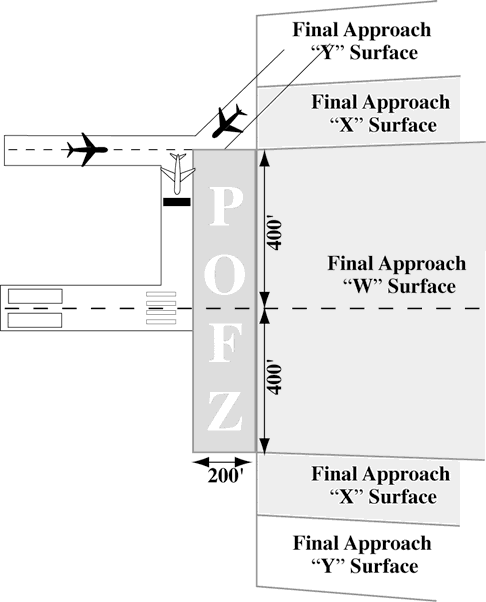
Section 8. Spacing and Sequencing
3-8-1. SEQUENCE/SPACING APPLICATION
Establish the sequence of arriving and departing aircraft by requiring them to adjust flight or ground operation, as necessary, to achieve proper spacing.
- PHRASEOLOGY
- CLEARED FOR TAKEOFF.
- CLEARED FOR TAKEOFF OR HOLD SHORT/HOLD IN POSITION/TAXI OFF THE RUNWAY (traffic).
- EXTEND DOWNWIND.
- MAKE SHORT APPROACH.
- NUMBER (landing sequence number), FOLLOW (description and location of traffic),
- or if traffic is utilizing another runway,
- TRAFFIC (description and location) LANDING RUNWAY (number of runway being used).
- TRAFFIC (description and location) LANDING THE PARALLEL RUNWAY
- CIRCLE THE AIRPORT.
- MAKE LEFT/RIGHT THREE-SIXTY/TWO SEVENTY.
- GO AROUND (additional instructions as necessary).
- CLEARED TO LAND.
- CLEARED:
- TOUCH-AND-GO, or
- STOP-AND-GO, or
- LOW APPROACH.
- CLEARED FOR THE OPTION, or
- OPTION APPROVED, or
- UNABLE OPTION, (alternate instructions). or
- UNABLE (type of option), OTHER OPTIONS APPROVED.
- NOTE:
- 1. The “Cleared for the Option” procedure will permit an instructor pilot/flight examiner/pilot the option to make a touch-and-go, low approach, missed approach, stop-and-go, or full stop landing. This procedure will only be used at those locations with an operational control tower and will be subject to ATC approval. After ATC approval of the option, the pilot should inform ATC as soon as possible of any delay on the runway during their stop-and-go or full stop landing.
- 2. For proper helicopter spacing, speed adjustments may be more practical than course changes.
- 3. Read back of hold short instructions apply when hold instructions are issued to a pilot in lieu of a takeoff clearance.
3-8-2. TOUCH-AND-GO OR STOP-AND-GO OR LOW APPROACH
Consider an aircraft cleared for touch-and-go, stop-and-go, or low approach as an arriving aircraft until it touches down (for touch-and-go), or makes a complete stop (for stop-and-go), or crosses the landing threshold (for low approach), and thereafter as a departing aircraft.
3-8-3. SIMULTANEOUS SAME DIRECTION OPERATION
Authorize simultaneous, same direction operations on parallel runways, on parallel landing strips, or on a runway and a parallel landing strip only when the following conditions are met:
- Operations are conducted in VFR conditions unless visual separation is applied.
- Two-way radio communication is maintained with the aircraft involved and pertinent traffic information is issued.
- The distance between the parallel runways or landing strips is in accordance with those specified in TBL 3-8-1.
| Aircraft category | Minimum distance (feet) between parallel | |
|---|---|---|
| Runway centerlines | Edges of adjacent strips or runway and strip | |
| Category I or Category II | 300 | 200 |
| If either aircraft is a Category III | 500 | 400 |
| If either aircraft is a Heavy | 700 | 600 |
- NOTE:
- 1. Aircraft Categories specified in Table 3-8-1 are Same Runway Separation (SRS) categories as indicated in Paragraph 3-9-6, Same Runway Separation.
- 2. When conducting Simultaneous Same Direction Operations (SSDO), applicable Wake Turbulence provisions apply.
3-8-4. SIMULTANEOUS OPPOSITE DIRECTION OPERATION
Authorize simultaneous opposite direction operations on parallel runways, on parallel landing strips, or on a runway and a parallel landing strip only when the following conditions are met:
- Operations are conducted in VFR conditions.
- Two-way radio communication is maintained with the aircraft involved and pertinent traffic information is issued.
- PHRASEOLOGY
- TRAFFIC (description) ARRIVING/DEPARTING/LOW APPROACH, OPPOSITE DIRECTION ON PARALLEL RUNWAY/LANDING STRIP.
- The distance between the runways or landing strips is in accordance with the minima in TBL 3-8-2.
| Type of Operation | Minimum distance (feet) between parallel | |
|---|---|---|
| Runway centerlines | Edges of adjacent strips or runway and strip | |
| Between sunrise and sunset | 1400 | 1400 |
| Between sunset and sunrise | 2800 | Not Authorized |
Section 9. Departure Procedures and Separation
3-9-1. DEPARTURE INFORMATION
Provide current departure information, as appropriate, to departing aircraft.
- Departure information contained in the ATIS broadcast may be omitted if the pilot states the appropriate ATIS code.
- Issue departure information by including the following:
- Runway in use. (May be omitted if pilot states “have the numbers.”)
- Surface wind from direct readout dial, wind shear detection system, or automated weather observing system information display. (May be omitted if pilot states “have the numbers.”)
- Altimeter setting. (May be omitted if pilot states “have the numbers.”)
- Time, when requested.
- Issue the official ceiling and visibility, when available, to a departing aircraft before takeoff as follows:
- To a VFR aircraft when weather is below VFR conditions.
- To an IFR aircraft when weather is below VFR conditions or highest takeoff minima, whichever is greater.
NOTE: Standard takeoff minimums are published in 14 CFR Section 91.175(f). Takeoff minima other than standard are prescribed for specific airports/runways and published in a tabular form supplement to the FAA instrument approach procedures charts and appropriate FAA Forms 8260.
- Issue the route for the aircraft/vehicle to follow on the movement area in concise and easy to understand terms. The taxi clearance must include the specific route to follow.
- USAF NOT APPLICABLE. An advisory to “check density altitude” when appropriate.
- REFERENCE
- FAA Order JO 7210.3, Para 2-10-6, Broadcast Density Altitude Advisory.
- Issue braking action for the runway in use as received from pilots when braking action advisories are in effect.
- Runway Condition Codes. Furnish RwyCC, as received from the Airport Operator, to aircraft via the ATIS.
- For opposite direction departure operations, controllers may verbally issue the RwyCC, as identified in the FICON NOTAM, in reverse order. Controllers must not include reversed RwyCC on the ATIS broadcast.
- When the ATIS is unavailable, and when the runway length available for departure has been temporarily shortened, controllers must ensure that pilots receive the runway number combined with a shortened announcement for all departing aircraft.
- PHRASEOLOGY
- RUNWAY (NUMBER) SHORTENED
- EXAMPLE
- “Runway Two-Seven shortened.”
3-9-2. DEPARTURE DELAY INFORMATION
USA/USAF/USN NOT APPLICABLE
When gate-hold procedures are in effect, issue the following departure delay information as appropriate:- REFERENCE
- FAA Order JO 7210.3, Para 10-4-3, Gate Hold Procedures.
- Advise departing aircraft the time at which the pilot can expect to receive engine startup advisory.
- PHRASEOLOGY
- GATE HOLD PROCEDURES ARE IN EFFECT. ALL AIRCRAFT CONTACT (position) ON (frequency) FOR ENGINE START TIME. EXPECT ENGINE START/TAXI (time).
- Advise departing aircraft when to start engines and/or to advise when ready to taxi.
- PHRASEOLOGY
- START ENGINES, ADVISE WHEN READY TO TAXI, or
- ADVISE WHEN READY TO TAXI.
- If the pilot requests to hold in a delay absorbing area, the request must be approved if space and traffic conditions permit.
- Advise all aircraft on GC/FD frequency upon termination of gate hold procedures.
- PHRASEOLOGY
- GATE HOLD PROCEDURES NO LONGER IN EFFECT.
3-9-3. DEPARTURE CONTROL INSTRUCTIONS
Inform departing IFR, SVFR, VFR aircraft receiving radar service, and TRSA VFR aircraft of the following:
- Before takeoff.
- Issue the appropriate departure control frequency and beacon code. The departure control frequency may be omitted if a SID has been or will be assigned and the departure control frequency is published on the SID.
- PHRASEOLOGY
- DEPARTURE FREQUENCY (frequency), SQUAWK (code).
- Inform all departing IFR military turboprop/turbojet aircraft (except transport and cargo types) to change to departure control frequency. If the local controller has departure frequency override, transmit urgent instructions on this frequency. If the override capability does not exist, transmit urgent instructions on the emergency frequency.
- PHRASEOLOGY
- CHANGE TO DEPARTURE.
- USAF. USAF control towers are authorized to inform all departing IFR military transport/cargo type aircraft operating in formation flight to change to departure control frequency before takeoff.
- Issue the appropriate departure control frequency and beacon code. The departure control frequency may be omitted if a SID has been or will be assigned and the departure control frequency is published on the SID.
- After takeoff.
- When the aircraft is about 1/2 mile beyond the runway end, instruct civil aircraft, and military transport, and cargo types to contact departure control, provided further communication with you is not required.
- Do not request departing military turboprop/turbojet aircraft (except transport and cargo types) to make radio frequency or radar beacon changes before the aircraft reaches 2,500 feet above the surface.
3-9-4. LINEUP AND WAIT (LUAW)
- The intent of LUAW is to position aircraft for an imminent departure. Authorize an aircraft to line up and wait, except as restricted in subpara g, when takeoff clearances cannot be issued because of traffic. Issue traffic information to any aircraft so authorized. Traffic information may be omitted when the traffic is another aircraft which has landed on or is taking off the runway and is clearly visible to the holding aircraft. Do not use conditional phrases such as “behind landing traffic” or “after the departing aircraft.”
- First state the runway number followed by the line up and wait clearance.
- PHRASEOLOGY
- RUNWAY (number), LINE UP AND WAIT.
NOTE: When using LUAW, an imminent departure is one that will not be delayed beyond the time that is required to ensure a safe operation. An aircraft should not be in LUAW status for more than 90 seconds without additional instructions.
- Procedures.
- At facilities without a safety logic system or facilities with the safety logic system in the limited configuration:
- (a) Do not issue a landing clearance to an aircraft requesting a full-stop, touch-and-go, stop-and-go, option, or unrestricted low approach on the same runway with an aircraft that is holding in position or taxiing to line up and wait until the aircraft in position starts takeoff roll.
- PHRASEOLOGY
- RUNWAY (number), CONTINUE, TRAFFIC HOLDING IN POSITION,
- or
- RUNWAY (number) (pattern instructions as appropriate) TRAFFIC HOLDING IN POSITION.
- EXAMPLE
- “American 528, Runway Two Three continue, traffic holding in position.”
- “Twin Cessna Four Four Golf, Runway One Niner Right, base approved, traffic holding in position.”
- “Baron Two Five Foxtrot, Runway One Niner, extend downwind, tower will call your base, traffic holding in position.”
- (b) Do not authorize an aircraft to LUAW if an aircraft has been cleared to land, touch-and-go, stop-and-go, option, or unrestricted low approach on the same runway.
- PHRASEOLOGY
- RUNWAY (number), CONTINUE, TRAFFIC HOLDING IN POSITION.
- EXAMPLE
- “American 528, Runway Two-Three continue, traffic holding in position.”
- (a) Do not issue a landing clearance to an aircraft requesting a full-stop, touch-and-go, stop-and-go, option, or unrestricted low approach on the same runway with an aircraft that is holding in position or taxiing to line up and wait until the aircraft in position starts takeoff roll.
- Except when reported weather conditions are less than ceiling 800 feet or visibility less than 2 miles, facilities using the safety logic system in the full core alert mode:
- (a) May issue a landing clearance for a full-stop, touch-and-go, stop-and-go, option, or unrestricted low approach to an arriving aircraft with an aircraft holding in position or taxiing to LUAW on the same runway, or
- (b) May authorize an aircraft to LUAW when an aircraft has been cleared for a full stop, touch-and-go, stop-and-go, option, or unrestricted low approach on the same runway.
- At facilities without a safety logic system or facilities with the safety logic system in the limited configuration:
- When an aircraft is authorized to line up and wait, inform it of the closest traffic within 6 flying miles requesting a full stop, touch-and-go, stop-and-go, option, or unrestricted low approach to the same runway.
- EXAMPLE
- “United Five, Runway One Eight, line up and wait. Traffic a Boeing Seven Thirty Seven, six mile final.”
- Do not authorize an aircraft to line up and wait when the departure point is not visible from the tower, unless the aircraft's position can be verified by ASDE or the runway is used for departures only.
- An aircraft may be authorized to line up and wait at an intersection between sunset and sunrise under the following conditions:
- The procedure must be approved by the appropriate Service Area Director of Air Traffic Operations.
- The procedure must be contained in a facility directive.
- The runway must be used as a departure-only runway.
- Only one aircraft at a time is permitted to line up and wait on the same runway.
- Document on FAA Form 7230-4, Daily Record of Facility Operation, the following: “LUAW at INT of RWY (number) and TWY (name) IN EFFECT” when using runway as a departure-only runway. “LUAW at INT of RWY (number) and TWY (name) SUSPENDED” when runway is not used as a departure-only runway.
- Do not authorize an aircraft to line up and wait at anytime when the intersection is not visible from the tower.
- Do not authorize aircraft to simultaneously line up and wait on the same runway, between sunrise an sunset, unless the local assist/local monitor position is staffed.
- USN. Do not authorize aircraft to line up and wait simultaneously on intersecting runways.
- PHRASEOLOGY
- CONTINUE HOLDING, or
- TAXI OFF THE RUNWAY.
- When aircraft are authorized to line up and wait on runways that intersect, traffic must be exchanged between that aircraft and the aircraft that is authorized to line up and wait, depart, or arrive to the intersecting runway(s).
- EXAMPLE
- “United Five, Runway Four, line up and wait, traffic holding Runway Three-One.”
- “Delta One, Runway Three-One, line up and wait, traffic holding Runway Four.”
Or, when issuing traffic information to an arrival aircraft and an aircraft that is holding on runway(s) that intersect(s):
- “Delta One, Runway Four, line up and wait, traffic landing Runway Three-One.”
- “United Five, Runway Three-One, cleared to land. Traffic holding in position Runway Four.”
Or, when issuing traffic information to a departing aircraft and an aircraft that is holding on runway(s) that intersect(s):
- “Delta One, Runway Three-One, line up and wait, traffic departing Runway Four.”
- “United Five, Runway Four, cleared for takeoff, traffic holding in position Runway Three-One.”
- When a local controller delivers or amends an ATC clearance to an aircraft awaiting departure and that aircraft is holding short of a runway or is holding in position on a runway, an additional clearance must be issued to prevent the possibility of the aircraft inadvertently taxiing onto the runway and/or beginning takeoff roll. In such cases, append one of the following ATC instructions as appropriate:
- HOLD SHORT OF RUNWAY, or
- HOLD IN POSITION.
- USAF/USN. When issuing additional instructions or information to an aircraft holding in takeoff position, include instructions to continue holding or taxi off the runway, unless it is cleared for takeoff.
- PHRASEOLOGY
- CONTINUE HOLDING, or
- TAXI OFF THE RUNWAY.
- When authorizing an aircraft to line up and wait at an intersection, state the runway intersection.
- PHRASEOLOGY
- RUNWAY (number) AT (taxiway designator), LINE UP AND WAIT.
- When two or more aircraft call the tower ready for departure, one or more at the full length of a runway and one or more at an intersection, state the location of the aircraft at the full length of the runway when authorizing that aircraft to line up and wait.
- PHRASEOLOGY
- RUNWAY (number), FULL-LENGTH, LINE UP AND WAIT.
- EXAMPLE
- “American Four Eighty Two, Runway Three-Zero full length, line up and wait.”
NOTE: The controller need not state the location of the aircraft departing the full length of the runway if there are no aircraft holding for departure at an intersection for that same runway.
- Do not use the term “full length” when the runway length available for departure has been temporarily shortened. On permanently shortened runways, do not use the term “full length” until the Chart Supplement U.S. is updated to include the change(s).
NOTE: The use of the term “full length” could be interpreted by the pilot(s) as the available runway length prior to the runway being shortened.
- Whenever a runway length has been temporarily or permanently shortened, state the word “shortened” immediately following the runway number as part of the line up and wait clearance.
- The addition of “shortened” must be included in the line up and wait clearance for the duration of the construction project when the runway is temporarily shortened.
- The addition of “shortened” must be included in the line up and wait clearance until the Chart Supplement U.S. is updated to include the change(s) when the runway is permanently shortened.
- PHRASEOLOGY
- RUNWAY (number) SHORTENED, LINE UP AND WAIT.
- EXAMPLE
- “Runway Two-Seven shortened, line up and wait.”
- REFERENCE
- FAA Order JO 7210.3, Para 10-3-12, Airport Construction
- FAA Order JO 7210.3, Para 10-3-13, Change in Runway Length Due to Construction
3-9-5. ANTICIPATING SEPARATION
Takeoff clearance need not be withheld until prescribed separation exists if there is a reasonable assurance it will exist when the aircraft starts takeoff roll.
- REFERENCE
- P/CG Term - Clear of the Runway.
3-9-6. SAME RUNWAY SEPARATION
Separate a departing aircraft from a preceding departing or arriving aircraft using the same runway by ensuring that it does not begin takeoff roll until:
- The other aircraft has departed and crossed the runway end or turned to avert any conflict. (See FIG 3-9-1.) If you can determine distances by reference to suitable landmarks, the other aircraft needs only be airborne if the following minimum distance exists between aircraft: (See FIG 3-9-2.)
- When only Category I aircraft are involved- 3,000 feet.
- When a Category I aircraft is preceded by a Category II aircraft- 3,000 feet.
- When either the succeeding or both are Category II aircraft- 4,500 feet.
- When either is a Category III aircraft- 6,000 feet.
- When the succeeding aircraft is a helicopter, visual separation may be applied in lieu of using distance minima.
FIG 3-9-1 Same Runway Separation [View 1] 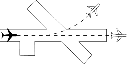
FIG 3-9-2 Same Runway Separation [View 2] 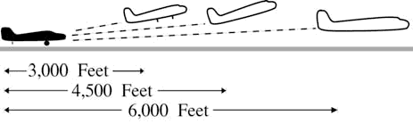
NOTE: Aircraft same runway separation (SRS) categories are specified in FAA Order JO 7360.1, Aircraft Type Designators and based upon the following definitions:
- CATEGORY I* small single-engine propeller driven aircraft weighing 12,500 lbs. or less, and all helicopters.
- CATEGORY II* small twin-engine propeller driven aircraft weighing 12,500 lbs. or less.
- CATEGORY III* all other aircraft.
- A preceding landing aircraft is clear of the runway. (See FIG 3-9-3.)
FIG 3-9-3 Preceding Landing Aircraft Clear of Runway 
- REFERENCE
- P/CG Term - Clear of the Runway.
WAKE TURBULENCE APPLICATION
- Do not issue clearances which imply or indicate approval of rolling takeoffs by super or heavy aircraft except as provided in Para 3-1-14, Ground Operations When Volcanic Ash is Present.
- Do not issue clearances to a small aircraft to line up and wait on the same runway behind a departing super or heavy aircraft to apply the necessary intervals.
- REFERENCE
- AC 90-23, Aircraft Wake Turbulence.
- The minima in Para 5-5-4, Minima, subparagraph g, may be applied in lieu of the time interval requirements in subparagraphs f, g, and h. When Para 5-5-4, Minima, is applied, ensure that the appropriate radar separation exists at or prior to the time an aircraft becomes airborne.
- REFERENCE
- FAA Order JO 7210.3, Para 2-1-16, Authorization for Separation Services by Towers.
- FAA Order JO 7210.3, Para 10-5-3, Functional Use of Certified Tower radar Displays.
- NOTE: The pilot may request additional separation, but should make this request before taxiing on the runway.
- NOTE: Takeoff clearance to the following aircraft should not be issued until the time interval has passed after the preceding aircraft begins takeoff roll.
- Separate aircraft taking off from the same runway or a parallel runway separated by less than 2,500 feet (See FIG 3-9-4.):
- Heavy, large, or small behind super - 3 minutes.
- Heavy, large, or small behind heavy - 2 minutes.
FIG 3-9-4 Same Runway Separation 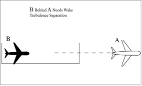
- Separate a small behind a B757 aircraft by 2 minutes when departing:
- The same runway or a parallel runway separated by less than 700 feet. (See FIG 3-9-5 and FIG FIG 3-9-6.)
FIG 3-9-5 Same Runway Separation 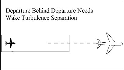
FIG 3-9-6 Parallel Runway Separated by Less than 700 Feet 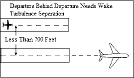
- A parallel runway separated by 700 feet or more if projected flight paths will cross. (See FIG 3-9-7).
FIG 3-9-7 Parallel Runway Separated by 700 Feet or More Projected Flight Paths Cross 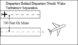
- The same runway or a parallel runway separated by less than 700 feet. (See FIG 3-9-5 and FIG FIG 3-9-6.)
- Separate aircraft departing from a parallel runway separated by 2,500 feet or more if projected flight paths will cross (See FIG 3-9-8):
- Heavy, large, or small behind super - 3 minutes.
- Heavy, large, or small behind heavy - 2 minutes.
FIG 3-9-8 Parallel Runways Separated by 2,500 feet or More 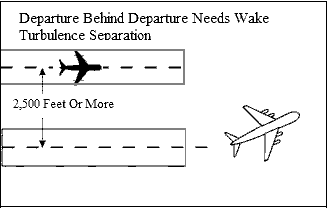
- Separate aircraft when operating on a runway with a displaced landing threshold if projected flight paths will cross when either a departure follows an arrival or an arrival follows a departure by the following minima:
- Heavy, large, or small behind super - 3 minutes.
- Heavy, large, or small behind heavy - 2 minutes.
- Small behind B757 - 2 minutes.
- Separate an aircraft behind another aircraft that has departed or made a low/missed approach when utilizing opposite direction takeoffs or landings on the same or parallel runways separated by less than 2,500 feet by the following minima:
- Heavy, large, or small behind super - 4 minutes.
- Heavy, large, or small behind heavy - 3 minutes
- Separate a small aircraft behind a B757 that has departed or made a low/missed approach by 3 minutes when utilizing opposite direction takeoffs or landings from:
- The same runway or a parallel runway separated by less than 700 feet.
- A parallel runway separated by 700 feet or more if projected flight paths will cross.
- Do not approve pilot requests to deviate from the required intervals contained in subparagraphs f through k.
- PHRASEOLOGY
- HOLD FOR WAKE TURBULENCE.
- Separate a small aircraft behind a large aircraft (except B757) that has departed or made a low/missed approach when utilizing opposite direction takeoffs on the same runway by 3 minutes unless a pilot has initiated a request to deviate from the time interval. In the latter case, issue a wake turbulence cautionary advisory before clearing the aircraft for takeoff. Controllers must not initiate or suggest a waiver of the time interval.
NOTE: A request for takeoff does not initiate a waiver request.
- Inform aircraft when it is necessary to hold in order to provide the required time interval.
3-9-7. WAKE TURBULENCE SEPARATION FOR INTERSECTION DEPARTURES
- Apply the following wake turbulence criteria for intersection departures:
- Separate a small aircraft weighing 12,500lbs. or less taking off from an intersection on the same runway (same or opposite direction takeoff) behind a departing small aircraft weighing more than 12,500 lbs. by ensuring that the aircraft does not start takeoff roll until at least 3 minutes after the preceding aircraft has taken off.
- Separate a small aircraft taking off from an intersection on the same runway (same or opposite direction takeoff) behind a departing large aircraft (except B757) by ensuring that the aircraft does not start takeoff roll until at least 3 minutes after the preceding aircraft has taken off.
- Separate a small aircraft taking off from an intersection (same or opposite direction takeoff) behind a preceding departing B757 aircraft by ensuring that the small aircraft does not start takeoff roll until at least 3 minutes after the B757 has taken off from:
- (a) The same runway or a parallel runway separated by lees than 700 feet.
- (b) Parallel runways separated by 700 feet or more, or parallel runways separated by 700 feet or more with the runway thresholds offset by 500 feet or more, if projected flight paths will cross.
- Separate aircraft departing from an intersection on the same runway (same or opposite direction takeoff), parallel runways separated by less than 2,500 feet, and parallel runways separated by less than 2,500 feet with the runway thresholds offset by 500 feet or more, by ensuring that the aircraft does not start take-off roll until the following intervals exist after the preceding aircraft has taken off:
NOTE: Apply Para 3-9-6, Same Runway Separation, subparagraph f to parallel runways separated by less than 2,500 feet with runway thresholds offset by less than 500 feet.
- (a) Heavy, large, or small behind super - 4 minutes.
- (b) Heavy, large, or small behind heavy - 3 minutes.
- Inform aircraft when it is necessary to hold in order to provide the required time interval.
- PHRASEOLOGY
- HOLD FOR WAKE TURBULENCE.
NOTE: Aircraft conducting touch-and-go and stop-and-go operations are considered to be departing from an intersection.
- The time interval is not required when:
- A pilot has initiated a request to deviate from the time intervals contained in subparagraph a1 or a2.
NOTE: A request for takeoff does not initiate a waiver request; the request for takeoff must be accomplished by a request to deviate from the time interval.
- USA NOT APPLICABLE. The intersection is 500 feet or less from the departure point of the preceding aircraft and both aircraft are taking off in the same direction.
- Successive touch-and-go or stop-and-go operations are conducted with any aircraft following an aircraft in the pattern that requires wake turbulence separation, or an aircraft departing the same runway that requires wake turbulence separation in accordance with subparagraphs a1, a2, a3, or a4 (except for super aircraft), provided the pilot is maintaining visual separation/spacing behind the preceding aircraft. Issue a wake turbulence cautionary advisory and the position of the larger aircraft.
NOTE: Not authorized with a Super as the lead or departure aircraft.
- If action is initiated to reduce the separation between successive touch-and-go or stop-and-go operations, apply the appropriate separation contained in subparagraph a1, a2, a3, or a4.
- A pilot has initiated a request to deviate from the time intervals contained in subparagraph a1 or a2.
- When applying the provision of subpara b:
- Issue a wake turbulence advisory before clearing the aircraft for takeoff.
- Do not clear the intersection departure for an immediate takeoff.
- Issue a clearance to permit the trailing aircraft to deviate from course enough to avoid the flight path of the preceding aircraft when applying subpara b1 or b2.
- Separation requirements in accordance with Para 3-9-6, Same Runway Separation, must also apply.
3-9-8. INTERSECTING RUNWAY/INTERSECTING FLIGHT PATH OPERATIONS
- Issue traffic information to each aircraft operating on intersecting runways.
- Separate departing aircraft from another aircraft using an intersecting runway by ensuring that the departure does not begin takeoff roll until one of the following exists:
- The preceding aircraft has departed and passed the intersection or is turning to avert any conflict. (See FIG 3-9-9).
FIG 3-9-9 Intersecting Runway Separation 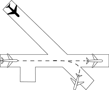
- A preceding arriving aircraft (See FIG 3-9-10)
- (a) Is clear of the landing runway, or
- (b) Has completed the landing roll on the runway and will hold short of the intersection, or
- (c) Has completed the landing roll and is observed turning at an exit point prior to the intersection, or
- (d) Has passed the intersection.
FIG 3-9-10 Intersecting Runway Separation 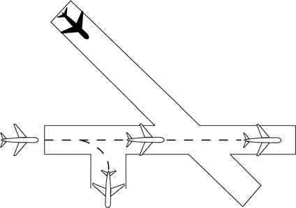
WAKE TURBULENCE APPLICATION
- Separate aircraft taking off behind a departing or landing aircraft on an intersecting runway if flight paths will cross (See FIG 3-9-11 and FIG 3-9-12):
NOTE: Takeoff clearance to the following aircraft should not be issued until the appropriate time interval has passed after the preceding aircraft began takeoff roll.
- (a) Heavy, large, or small behind super - 3 minutes.
- (b) Heavy, large, or small behind heavy - 2 minutes.
- (c) Small behind B757 - 2 minutes.
FIG 3-9-11 Departure Behind Departure on Intersecting Runway 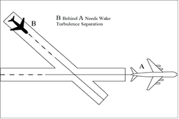
FIG 3-9-12 Departure Behind Arrival on Intersecting Runway 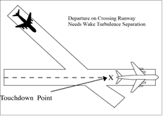
- Pilot requests to deviate from the required time intervals must not be approved if the preceding aircraft requires wake turbulence separation.
- The preceding aircraft has departed and passed the intersection or is turning to avert any conflict. (See FIG 3-9-9).
3-9-9. NONINTERSECTING CONVERGING RUNWAY OPERATIONS
- Separate departing aircraft from an aircraft using a nonintersecting runway when the flight paths intersect by ensuring that the departure does not begin takeoff roll until one of the following exists:
- The preceding aircraft has departed and crossed the departure runway, or is turning to avert any conflict. (See FIG 3-9-13).
FIG 3-9-13 Intersecting Runway Separation 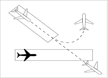
- A preceding arriving aircraft has completed the landing roll and will hold short of the projected intersection, passed the projected intersection, or has crossed over the departure runway (See FIG 3-9-14 and FIG 3-9-15).
FIG 3-9-14 Intersecting Runway Separation 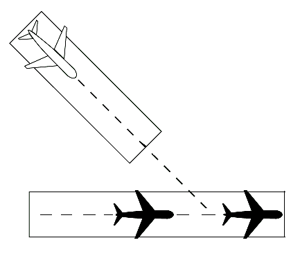
FIG 3-9-15 Intersecting Runway Separation 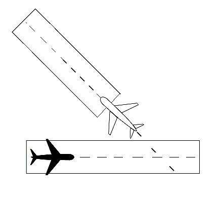
- If the extended centerline of a runway crosses a converging runway or the extended centerline of a converging runway at a distance of 1NM or less from either departure end, apply the provisions of Para 3-9-8, Intersecting Runway/Intersecting Flight Path Operations, unless the facility is using aids specified in a facility directive, (may include but are not limited to, Arrival/Departure Window (ADW), ASDE-X Virtual Runway Intersection Point (VRIP), cut-off points or automation). (See FIG3-9-16 and FIG 3-9-17.)
- REFERENCE
- FAA Order JO 7210.3, Para 10-3-15, Go-Around/Missed Approach
FIG 3-9-16 Intersecting Runway Separation 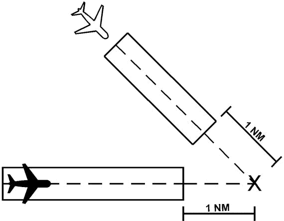
FIG 3-9-17 Intersecting Runway Separation 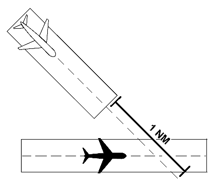
WAKE TURBULENCE APPLICATION
- Separate aircraft taking off behind a departing aircraft on a crossing runway if projected flight paths will cross (See FIG 3-9-18):
- Heavy, large, or small behind super - 3 minutes.
- Heavy, large, or small behind heavy - 2 minutes.
- Small behind B757 - 2 minutes.
FIG 3-9-18 Intersecting Runway Separation 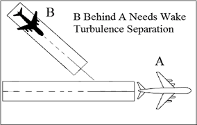
NOTE: Takeoff clearance to the following aircraft should not be issued until the time interval has passed from when the preceding aircraft began takeoff roll.
- Separate aircraft departing behind a landing aircraft on a crossing runway if the departure will fly through the airborne path of the arrival (See FIG 3-9-19):
- Heavy, large, or small behind super - 3 minutes.
- Heavy, large, or small behind heavy - 2 minutes.
- Small behind B757 - 2 minutes.
FIG 3-9-19 Intersecting Runway Separation 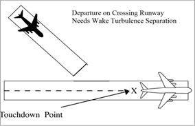
- Do not approve pilot requests to deviate from the required time interval if the preceding aircraft requires wake turbulence separation.
3-9-10. TAKEOFF CLEARANCE
- When issuing a clearance for takeoff, first state the runway number followed by the takeoff clearance.
- PHRASEOLOGY
- RUNWAY (number), CLEARED FOR TAKEOFF.
- EXAMPLE
- “RUNWAY TWO SEVEN, CLEARED FOR TAKEOFF.”
NOTE: Turbine-powered aircraft may be considered ready for takeoff when they reach the runway unless they advise otherwise.
- When clearing an aircraft for takeoff from an intersection, state the runway intersection.
- PHRASEOLOGY
- RUNWAY (number) AT (taxiway designator) CLEARED FOR TAKEOFF.
- When two or more aircraft call the tower ready for departure, one or more at the full length of a runway and one or more at an intersection, state the location of the aircraft at the full length of the runway when clearing that aircraft for takeoff.
- PHRASEOLOGY
- RUNWAY (number), FULL LENGTH, CLEARED FOR TAKEOFF.
- EXAMPLE
- “American Four Eighty Two, Runway Three Zero full length, cleared for takeoff.”
- The controller must ensure that all runways along the taxi route that lead to the departure runway are crossed before the takeoff clearance is issued, except as stated in para 3-9-10e.
FIG 3-9-20 Runway/Taxiway Proximity 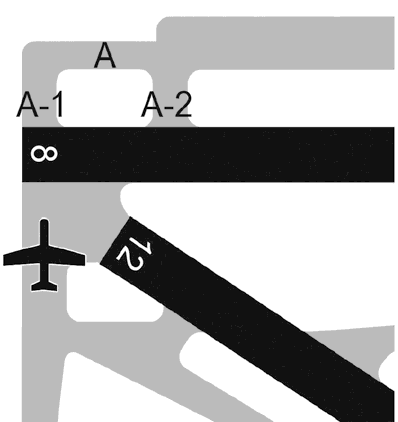
- At those airports where the airport configuration does not allow for an aircraft to completely cross one runway and hold short of the departure runway and/or where airports do not have runway hold markings between runways, state the runway to be crossed with the takeoff clearance if the aircraft is not able to complete a runway crossing before reaching its departure runway.
- PHRASEOLOGY
- CROSS RUNWAY (number), RUNWAY (number) CLEARED FOR TAKEOFF.
- EXAMPLE
- “CROSS RUNWAY TWO FOUR LEFT, RUNWAY TWO FOUR RIGHT, CLEARED FOR TAKEOFF.”
FIG 3-9-21 Runway/Taxiway Proximity 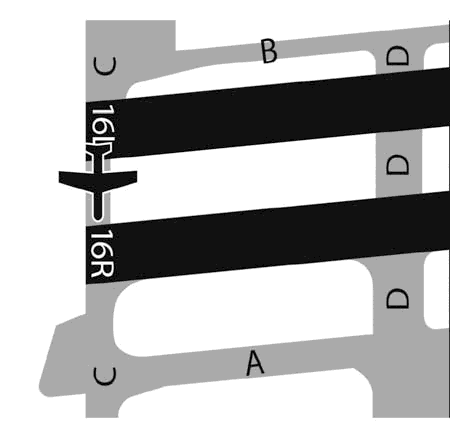
- REFERENCE
- FAA Order JO 7210.3, Para 10-3-10, Takeoff Clearance.
- P/CG Term - Clear of the Runway.
- Do not use the term “full length” when the runway length available for departure has been temporarily shortened. On permanently shortened runways, do not use the term “full length” until the Chart Supplement U.S. is updated to include the change(s).
NOTE: The use of the term “full length” could be interpreted by the pilot(s) as the available runway length prior to the runway being shortened.
- Whenever a runway length has been temporarily or permanently shortened, state the word “shortened” immediately following the runway number as part of the takeoff clearance. This information must be issued in conjunction with the takeoff clearance.
- The addition of “shortened” must be included in the takeoff clearance for the duration of the construction project when the runway is temporarily shortened.
- The addition of “shortened” must be included in the takeoff clearance until the Chart Supplement U.S. is updated to include the change(s) when the runway is permanently shortened.
- PHRASEOLOGY
- RUNWAY (number) SHORTENED, CLEARED FOR TAKEOFF.
- EXAMPLE
- “Runway Two-Seven shortened, cleared for takeoff.”
- PHRASEOLOGY
- RUNWAY (number) AT (taxiway designator) INTERSECTION DEPARTURE SHORTENED, CLEARED FOR TAKEOFF.
- EXAMPLE
- “Runway Two-Seven at Juliet, intersection departure shortened, cleared for takeoff.”
- REFERENCE
- FAA Order JO 7210.3, Para 10-3-12, Airport Construction
- FAA Order JO 7210.3, Para 10-3-13, Change in Runway Length Due to Construction
- USAF. When an aircraft is cleared for takeoff, inform it of the closest traffic within 6 miles on final approach to the same runway. If the approaching aircraft is on a different frequency, inform it of the departing aircraft.
- USA/USN/USAF. Issue surface wind and takeoff clearance to aircraft.
- PHRASEOLOGY
- RUNWAY (number), WIND (surface wind in direction and velocity). CLEARED FOR TAKEOFF.
3-9-11. CANCELLATION OF TAKEOFF CLEARANCE
Cancel a previously issued clearance for takeoff and inform the pilot of the reason if circumstances require. Once an aircraft has started takeoff roll, cancel the takeoff clearance only for the purpose of safety.
NOTE: In no case should a takeoff clearance be canceled after an aircraft has started its takeoff roll solely for the purpose of meeting traffic management requirements/EDCT.
- PHRASEOLOGY
- CANCEL TAKEOFF CLEARANCE (reason).
Section 10. Arrival Procedures and Separation
3-10-1. LANDING INFORMATION
Provide current landing information, as appropriate, to arriving aircraft. Landing information contained in the ATIS broadcast may be omitted if the pilot states the appropriate ATIS code. Runway, wind, and altimeter may be omitted if a pilot uses the phrase “have numbers.” Issue landing information by including the following:
NOTE: Pilot use of “have numbers” does not indicate receipt of the ATIS broadcast.
- Specific traffic pattern information (may be omitted if the aircraft is to circle the airport to the left).
- PHRASEOLOGY
- ENTER LEFT/RIGHT BASE.
- STRAIGHT-IN.
- MAKE STRAIGHT-IN.
- STRAIGHT-IN APPROVED.
- RIGHT TRAFFIC.
- MAKE RIGHT TRAFFIC.
- RIGHT TRAFFIC APPROVED.
- CONTINUE.
NOTE: Additional information should normally be issued with instructions to continue. Example: “continue, report one mile final”; “continue, expect landing clearance two mile final”; etc.
- Runway in use.
- Surface wind.
- Altimeter setting.
- Any supplementary information.
- Clearance to land.
- Requests for additional position reports. Use prominent geographical fixes which can be easily recognized from the air, preferably those depicted on sectional charts. This does not preclude the use of the legs of the traffic pattern as reporting points.
NOTE: At some locations, VFR checkpoints are depicted on sectional aeronautical and terminal area charts. In selecting geographical fixes, depicted VFR checkpoints are preferred unless the pilot exhibits a familiarity with the local area.
- Ceiling and visibility if either is below basic VFR minima.
- Low level wind shear or microburst advisories when available.
- Issue braking action for the runway in use as received from pilots when braking action advisories are in effect.
- Runway Condition Codes. Furnish RwyCC, as received from the Airport Operator, to aircraft via the ATIS.
- For opposite direction arrival operations, controllers may verbally issue the RwyCC, as identified in the FICON NOTAM, in reverse order. Controllers must not include reversed RwyCC on the ATIS broadcast.
- If the pilot does not indicate the appropriate ATIS code, and when a runway has been shortened, controllers must ensure that pilots receive the runway number combined with a shortened announcement for all arriving aircraft.
3-10-2. FORWARDING APPROACH INFORMATION BY NONAPPROACH CONTROL FACILITIES
- Forward the following, as appropriate, to the control facility having IFR jurisdiction in your area. You may eliminate those items that, because of local conditions or situations, are fully covered in a letter of agreement or a facility directive.
- When you clear an arriving aircraft for a visual approach.
- Aircraft arrival time.
- Cancellation of IFR flight plan.
- Information on a missed approach, unreported, or overdue aircraft.
- Runway in use.
- Weather as required.
- When the weather is below 1,000 feet or 3 miles or the highest circling minimums, whichever is greater, issue current weather to aircraft executing an instrument approach if it changes from that on the ATIS or that previously forwarded to the center/approach control.
3-10-3. SAME RUNWAY SEPARATION
- Separate an arriving aircraft from another aircraft using the same runway by ensuring that the arriving aircraft does not cross the landing threshold until one of the following conditions exists or unless authorized in para 3-10-10, Altitude Restricted Low Approach.
- The other aircraft has landed and is clear of the runway. (See FIG 3-10-1.) Between sunrise and sunset, if you can determine distances by reference to suitable landmarks and the other aircraft has landed, it need not be clear of the runway if the following minimum distance from the landing threshold exists:
- REFERENCE
- P/CG Term - Clear of the Runway.
FIG 3-10-1 Same Runway Separation 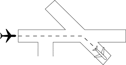
- (a) When a Category I aircraft is landing behind a Category I or II- 3,000 feet. (See FIG 3-10-2.)
FIG 3-10-2 Same Runway Separation 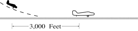
- (b) When a Category II aircraft is landing behind a Category I or II- 4,500 feet.
(See FIG 3-10-3.)
FIG 3-10-3 Same Runway Separation 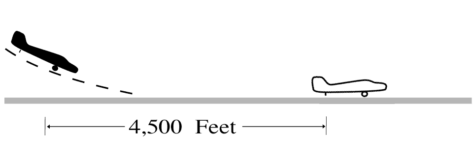
- The other aircraft has departed and crossed the runway end. (See FIG 3-10-4). If you can determine distances by reference to suitable landmarks and the other aircraft is airborne, it need not have crossed the runway end if the following minimum distance from the landing threshold exists:
- (a) Category I aircraft landing behind Category I or II- 3,000 feet.
- (b) Category II aircraft landing behind Category I or II- 4,500 feet.
- (c) When either is a category III aircraft- 6,000 feet. (See FIG 3-10-5.)
FIG 3-10-4 Same Runway Separation 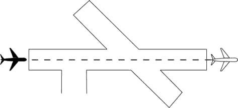
FIG 3-10-5 Same Runway Separation 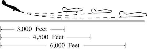
- When the succeeding aircraft is a helicopter, visual separation may be applied in lieu of using distance minima.
WAKE TURBULENCE APPLICATION
- The other aircraft has landed and is clear of the runway. (See FIG 3-10-1.) Between sunrise and sunset, if you can determine distances by reference to suitable landmarks and the other aircraft has landed, it need not be clear of the runway if the following minimum distance from the landing threshold exists:
- Issue wake turbulence advisories, and the position, altitude if known, and the direction of flight of:
- The super or heavy to aircraft landing behind a departing/arriving super or heavy on the same or parallel runways separated by less than 2,500 feet.
- The B757/large aircraft to a small aircraft landing behind a departing/arriving B757/large aircraft on the same or parallel runways separated by less than 2,500 feet.
- REFERENCE
- AC 90-23, Aircraft Wake Turbulence, Para 12, Pilot Responsibility.
- FAA Order JO 7110.65, Para 3-10-10, Altitude Restricted Low Approach.
- EXAMPLE
- “Runway two seven left cleared to land, caution wake turbulence, heavy Boeing 747 departing runway two seven right.”
- “Number two follow Boeing 757 on 2-mile final. Caution wake turbulence.”
- “Traffic, Boeing 737 on 2 mile final to the parallel runway, runway two six right, cleared to land. Caution wake turbulence.”
3-10-4. INTERSECTING RUNWAY/INTERSECTING FLIGHT PATH SEPARATION
Issue traffic information to each aircraft operating on intersecting runways.
- Separate an arriving aircraft using one runway from another aircraft using an intersecting runway or a nonintersecting runway when the flight paths intersect by ensuring that the arriving aircraft does not cross the landing threshold or flight path of the other aircraft until one of the following conditions exists:
- The preceding aircraft has departed and passed the intersection/flight path or is airborne and turning to avert any conflict. (See FIG 3-10-6 and FIG 3-10-7.)
FIG 3-10-6 Intersecting Runway Separation 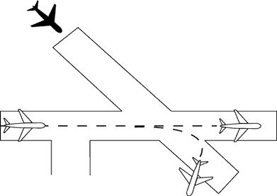
FIG 3-10-7 Intersecting Runway Separation 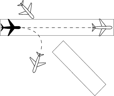
- A preceding arriving aircraft is clear of the landing runway, completed landing roll and will hold short of the intersection/flight path, or has passed the intersection/flight path. (See FIG 3-10-8 and FIG 3-10-9.)
FIG 3-10-8 Intersecting Runway Separation 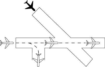
FIG 3-10-9 Intersecting Runway Separation 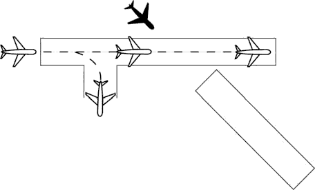
NOTE: When visual separation is being applied by the tower, appropriate control instructions and traffic advisories must be issued to ensure go around or missed approaches avert any conflict with the flight path of traffic on the other runway.
- The preceding aircraft has departed and passed the intersection/flight path or is airborne and turning to avert any conflict. (See FIG 3-10-6 and FIG 3-10-7.)
- USA/USAF/USN NOT APPLICABLE. An aircraft may be authorized to takeoff from one runway while another aircraft lands simultaneously on an intersecting runway or an aircraft lands on one runway while another aircraft lands simultaneously on an intersecting runway, or an aircraft lands to hold short of an intersecting taxiway or some other predetermined point such as an approach/departure flight path using procedures specified in the current LAHSO directive. The procedure must be approved by the air traffic manager and be in accordance with a facility directive. The following conditions apply:
NOTE: Application of these procedures does not relieve controllers from the responsibility of providing other appropriate separation contained in this order.
- REFERENCE
- FAA Order JO 7210.3, Para 10-3-7, Land and Hold Short Operations (LAHSO).
- A simultaneous takeoff and landing operation must only be conducted in VFR conditions.
- Instruct the landing aircraft to hold short of the intersecting runway being used by the aircraft taking off. In the case of simultaneous landings and no operational benefit is lost, restrict the aircraft of the lesser weight category (if known). LAHSO clearances must only be issued to aircraft that are listed in the current LAHSO directive, whose Available Landing Distance (ALD) does not exceed the landing distance requirement for the runway condition.
- PHRASEOLOGY
- HOLD SHORT OF RUNWAY (runway number), (traffic, type aircraft or other information).
NOTE: Pilots who prefer to use the full length of the runway or a runway different from that specified are expected to advise ATC prior to landing.
- Issue traffic information to both aircraft involved and obtain an acknowledgment from each. Request a read back of hold short instructions when they are not received from the pilot of the restricted aircraft.
- EXAMPLE
- 1. “Runway one eight cleared to land, hold short of runway one four left, traffic, (type aircraft) landing runway one four left.”
(When pilot of restricted aircraft responds with only acknowledgment):
“Runway one four left cleared to land, traffic, (type aircraft) landing runway one eight will hold short of the intersection.”
“Read back hold short instructions.”
- 2. “Runway three six cleared to land, hold short of runway three three, traffic, (type aircraft) departing runway three three.”
“Traffic, (type aircraft) landing runway three six will hold short of the intersection, runway three three cleared for takeoff.”
- Issue the measured distance from the landing threshold to the hold short point rounded “down” to the nearest 50-foot increment if requested by either aircraft.
- EXAMPLE
- “Five thousand fifty feet available.”
- The conditions in subparas b2, 3, and 4 must be met in sufficient time for the pilots to take other action, if desired, and no later than the time landing clearance is issued.
- Land and Hold Short runways must be free of any contamination as described in the current LAHSO directive, with no reports that braking action is less than good.
- There is no tailwind for the landing aircraft restricted to hold short of the intersection. The wind may be described as “calm” when appropriate.
- The aircraft required landing distances are listed in the current LAHSO directive.
- STOL aircraft operations are in accordance with a letter of agreement with the aircraft operator/pilot or the pilot confirms that it is a STOL aircraft.
WAKE TURBULENCE APPLICATION
- Separate aircraft landing behind a departing aircraft on a crossing runway if the arrival will fly through the airborne path of the departure by the appropriate radar separation or the following interval: (See FIG 3-10-10):
- Heavy, large, or small behind super - 3 minutes.
- Heavy, large, or small behind heavy - 2 minutes.
- Small behind B757 - 2 minutes.
- Issue wake turbulence cautionary advisories, the position, altitude if known, and direction of flight of the super, heavy, or B757 to:
FIG 3-10-10 Intersecting Runway Separation 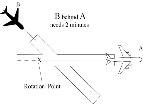
- All aircraft landing on a crossing runway behind a departing super or heavy, or a small aircraft landing on a crossing runway behind a departing B757, if the arrival flight path will cross the takeoff path behind the departing aircraft rotation point. (See FIG 3-10-11.)
FIG 3-10-11 Intersecting Runway Separation 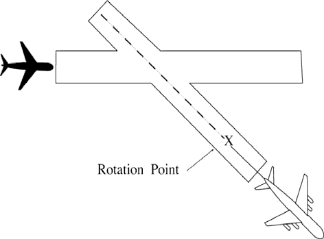
- EXAMPLE
- “Runway niner cleared to land. Caution wake turbulence, heavy C-One Forty One departing runway one five.”
- All VFR aircraft landing on a crossing runway behind an arriving super or heavy, and VFR small aircraft landing on a crossing runway behind a B757, if the arrival flight paths will cross. (See FIG 3-10-12.)
FIG 3-10-12 Intersecting Runway Separation 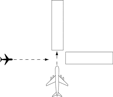
- EXAMPLE
- “Runway niner cleared to land. Caution wake turbulence, Boeing Seven Fifty Seven landing runway three six.”
- All aircraft landing on a crossing runway behind a departing super or heavy, or a small aircraft landing on a crossing runway behind a departing B757, if the arrival flight path will cross the takeoff path behind the departing aircraft rotation point. (See FIG 3-10-11.)
3-10-5. LANDING CLEARANCE
- When issuing a clearance to land, first state the runway number followed by the landing clearance. If the landing runway is changed, controllers must preface the landing clearance with “Change to runway” followed by the runway number. Controllers must then restate the runway number followed by the landing clearance.
- PHRASEOLOGY
- RUNWAY (number) CLEARED TO LAND.
- or
- CHANGE TO RUNWAY (number, RUNWAY (number)CLEARED TO LAND.
NOTE: The purpose of the “change to runway” phraseology and restating the runway number is to emphasize to the pilot that they are being cleared to land on a runway other than what they were expecting.
- When you become aware that an aircraft is aligned with the wrong surface, inform the pilot and:
- Issue control instructions/clearances, or
- EXAMPLE
- “United four twenty three, go-around, you appear to be aligned with the wrong runway.”
- “American sixty three, go-around, you appear to be aligned with a taxiway.”
- “Southwest two thirty nine, you appear to be aligned with Runway 27 Left (pertinent information), Runway 27 Left, cleared to land.”
- If time permits, verify the pilot is aligned with the correct runway. Issue control instructions/clearances as necessary.
- EXAMPLE
- “Twin Cessna four one four lima bravo, verify you are aligned with Runway 27 Left.”
- Issue control instructions/clearances, or
- Procedures.
- Facilities without a safety logic system or facilities with the safety logic system inoperative or in the limited configuration must not clear an aircraft for a full-stop, touch-and-go, stop-and-go, option, or unrestricted low approach when a departing aircraft has been instructed to line up and wait or is holding in position on the same runway. The landing clearance may be issued once the aircraft in position has started takeoff roll.
- Facilities using safety logic in the full core alert runway configuration may issue a landing clearance, full-stop, touch-and-go, stop-and-go, option, or unrestricted low approach to an arriving aircraft with an aircraft holding in position or taxiing to LUAW on the same runway except when reported weather conditions are less than ceiling 800 feet or visibility less than 2 miles.
- Inform the closest aircraft that is requesting a full-stop, touch-and-go, stop-and-go, option, or unrestricted low approaches when there is traffic authorized to line up and wait on the same runway.
- EXAMPLE
- “Delta One, Runway One-Eight, continue, traffic holding in position.”
- “Delta One, Runway One-Eight, cleared to land. Traffic holding in position.”
- “Twin Cessna Four Four Golf, Runway One-Niner base approved, traffic holding in position.”
- “Baron Two Five Foxtrot, Runway One-Niner Right extend downwind, tower will call your base, traffic holding in position.”
- USA/USN/USAF. Issue runway identifier along with surface wind when clearing an aircraft to land, touch and go, stop and go, low approach, or the option.
- PHRASEOLOGY
- RUNWAY (number), WIND (surface wind direction and velocity), CLEARED TO LAND.
NOTE: A clearance to land means that appropriate separation on the landing runway will be ensured. A landing clearance does not relieve the pilot from compliance with any previously issued restriction.
- Whenever a runway length has been temporarily or permanently shortened, state the word “shortened” immediately following the runway number as part of the landing clearance. This information must be issued in conjunction with the landing clearance.
- The addition of “shortened” must be included in the landing clearance for the duration of the construction project when the runway is temporarily shortened.
- The addition of “shortened” must be included in the landing clearance until the Chart Supplement U.S. is updated to include the change(s) when the runway is permanently shortened.
- PHRASEOLOGY
- RUNWAY (number) SHORTENED, CLEARED TO LAND.
- EXAMPLE
- “Runway Two-Seven shortened, cleared to land.”
- If landing clearance is temporarily withheld, insert the word “shortened” immediately after the runway number to advise the pilot to continue.
- PHRASEOLOGY
- RUNWAY (number) SHORTENED, CONTINUE.
- EXAMPLE
- “Runway Two-Seven shortened, continue.”
- REFERENCE
- FAA Order JO 7210.3, Para 10-3-12, Airport Construction
- FAA Order JO 7210.3, Para 10-3-13, Change in Runway Length Due to Construction
3-10-6. ANTICIPATING SEPARATION
- Landing clearance to succeeding aircraft in a landing sequence need not be withheld if you observe the positions of the aircraft and determine that prescribed runway separation will exist when the aircraft crosses the landing threshold. Issue traffic information to the succeeding aircraft if a preceding arrival has not been previously reported and when traffic will be departing prior to their arrival.
- EXAMPLE
- “American Two Forty-Five, Runway One-Eight, cleared to land, number two following a United Seven-Thirty-Seven two mile final. Traffic will depart prior to your arrival.”
- “American Two Forty-Five, Runway One-Eight, cleared to land. Traffic will depart prior to your arrival.”
NOTE: Landing sequence number is optional at tower facilities where the arrival sequence to the runway is established by the approach control.
- Anticipating separation must not be applied when conducting LUAW operations, except as authorized in paragraph 3-10-5 b2. Issue applicable traffic information when using this provision.
- EXAMPLE
- “American Two Forty-Five, Runway One-Eight, cleared to land. Traffic will be a Boeing Seven-Fifty-Seven holding in position.”
- REFERENCE
- P/CG Term - Clear of the Runway.
3-10-7. LANDING CLEARANCE WITHOUT VISUAL OBSERVATION
When an arriving aircraft reports at a position where he/she should be seen but has not been visually observed, advise the aircraft as a part of the landing clearance that it is not in sight and restate the landing runway.
- PHRASEOLOGY
- NOT IN SIGHT, RUNWAY (number) CLEARED TO LAND.
NOTE: Aircraft observance on the CTRD satisfies the visually observed requirement.
3-10-8. WITHHOLDING LANDING CLEARANCE
Do not withhold a landing clearance indefinitely even though it appears a violation of Title 14 of the Code of Federal Regulations has been committed. The apparent violation might be the result of an emergency situation. In any event, assist the pilot to the extent possible.
3-10-9. RUNWAY EXITING
- Instruct aircraft where to turn-off the runway after landing, when appropriate, and advise the aircraft to hold short of a runway or taxiway if required for traffic.
- PHRASEOLOGY
- TURN LEFT/RIGHT (taxiway/runway), or
- IF ABLE, TURN LEFT/RIGHT (taxiway/runway)
- and if required
- HOLD SHORT OF (runway).
NOTE: Runway exiting or taxi instructions should not normally be issued to an aircraft prior to, or immediately after, touchdown.
- Taxi instructions must be provided to the aircraft by the local controller when:
- Compliance with ATC instructions will be required before the aircraft can change to ground control, or
- The aircraft will be required to enter an active runway in order to taxi clear of the landing runway.
- EXAMPLE
- “U.S. Air Ten Forty Two, turn right next taxiway, cross runway two one, contact ground point seven.”
- “U.S. Air Ten Forty Two, turn right on Alfa/next taxiway, cross Bravo, hold short of Charlie, contact ground point seven.”
- NOTE:
- 1. An aircraft is expected to taxi clear of the runway unless otherwise directed by ATC. Pilots must not exit the landing runway on to an intersecting runway unless authorized by ATC. In the absence of ATC instructions, an aircraft should taxi clear of the landing runway by clearing the hold position marking associated with the landing runway even if that requires the aircraft to protrude into or enter another taxiway/ramp area. This does not authorize an aircraft to cross a subsequent taxiway or ramp after clearing the landing runway.
- REFERENCE
- P/CG Term - Clear of the Runway.
- 2. The pilot is responsible for ascertaining when the aircraft is clear of the runway by clearing the runway holding position marking associated with the landing runway.
- Ground control and local control must protect a taxiway/runway/ramp intersection if an aircraft is required to enter that intersection to clear the landing runway.
- REFERENCE
- FAA Order JO 7210.3, Para 10-1-7, Use of Active Runways.
- Request a read back of runway hold short instructions when not received from the pilot.
- EXAMPLE
- “American Four Ninety-two, turn left at Taxiway Charlie, hold short of Runway 27 Right.”
- or
- “American Four Ninety-two, turn left at Charlie, hold short of Runway 27 Right.”
- “American Four Ninety Two, Roger.”
- “American Four Ninety-two, read back hold instructions.”
NOTE: Read back hold instructions phraseology may be initiated for any point on a movement area when the controller believes the read back is necessary.
3-10-10. ALTITUDE RESTRICTED LOW APPROACH
A low approach with an altitude restriction of not less than 500 feet above the airport may be authorized except over an aircraft in takeoff position or a departure aircraft. Do not clear aircraft for restricted altitude low approaches over personnel unless airport authorities have advised these personnel that the approaches will be conducted. Advise the approaching aircraft of the location of applicable ground traffic, personnel, or equipment.
- NOTE:
- 1. The 500 feet restriction is a minimum. Higher altitudes should be used when warranted. For example, 1,000 feet is more appropriate for super or heavy aircraft operating over unprotected personnel or small aircraft on or near the runway.
- 2. This authorization includes altitude restricted low approaches over preceding landing or taxiing aircraft. Restricted low approaches are not authorized over aircraft in takeoff position or departing aircraft.
- PHRASEOLOGY
- CLEARED LOW APPROACH AT OR ABOVE (altitude). TRAFFIC (description and location).
- REFERENCE
- FAA Order JO 7110.65, Para 3-1-5, Vehicles/Equipment/Personnel on Runways.
- FAA Order JO 7110.65, Para 3-1-6, Traffic Information.
- FAA Order JO 7110.65, Para 3-2-1, Light Signals.
- FAA Order JO 7110.65, Para 3-3-3, Timely Information.
- FAA Order JO 7110.65, Para 3-9-4, Line Up and Wait (LUAW).
- FAA Order JO 7110.65, Para 3-10-3, Same Runway Separation.
3-10-11. CLOSED TRAFFIC
Approve/disapprove pilot requests to remain in closed traffic for successive operations subject to local traffic conditions.
- PHRASEOLOGY
- LEFT/RIGHT (if required) CLOSED TRAFFIC APPROVED. REPORT (position if required),
- or
- UNABLE CLOSED TRAFFIC, (additional information as required).
NOTE: Segregated traffic patterns for helicopters to runways and other areas may be established by letter of agreement or other local operating procedures.
3-10-12. OVERHEAD MANEUVER
Issue the following to arriving aircraft that will conduct an overhead maneuver:
- Pattern altitude and direction of traffic. Omit either or both if standard or when you know the pilot is familiar with a nonstandard procedure.
- PHRASEOLOGY
- PATTERN ALTITUDE (altitude). RIGHT TURNS.
- Request for report on initial approach.
- PHRASEOLOGY
- REPORT INITIAL.
- “Break” information and request for pilot report. Specify the point of “break” only if nonstandard. Request the pilot to report “break” if required for traffic or other reasons.
- PHRASEOLOGY
- BREAK AT (specified point). REPORT BREAK.
- Overhead maneuver patterns are developed at airports where aircraft have an operational need to conduct the maneuver. An aircraft conducting an overhead maneuver is VFR and the IFR flight plan is cancelled when the aircraft reaches the “initial point” on the initial approach portion of the maneuver. The existence of a standard overhead maneuver pattern does not eliminate the possible requirement for an aircraft to conform to conventional rectangular patterns if an overhead maneuver cannot be approved.
NOTE: Aircraft operating to an airport without a functioning control tower must initiate cancellation of the IFR flight plan prior to executing the overhead maneuver or after landing.
FIG 3-10-13 Overhead Maneuver 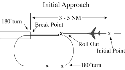
- EXAMPLE
- “Air Force Three Six Eight, Runway Six, wind zero seven zero at eight, pattern altitude six thousand, report initial.”
- “Air Force Three Six Eight, break at midfield, report break.”
- “Air Force Three Six Eight, cleared to land.”
- “Alfa Kilo Two Two, Runway Three One, wind three three zero at one four, right turns, report initial.”
- “Alfa Kilo Two Two, report break.” “Alfa Kilo Two Two, cleared to land.”
- Timely and positive controller action is required to prevent a conflict when an overhead pattern could extend into the path of a departing or a missed approach aircraft. Local procedures and/or coordination requirements should be set forth in an appropriate letter of agreement, facility directive, base flying manual etc., when the frequency of occurrence warrants.
3-10-13. SIMULATED FLAMEOUT (SFO) APPROACHES/EMERGENCY LANDING PATTERN (ELP) OPERATIONS/PRACTICE PRECAUTIONARY APPROACHES
- Authorize military aircraft to make SFO/ELP/ practice precautionary approaches if the following conditions are met:
- A letter of agreement or local operating procedure is in effect between the military flying organization and affected ATC facility.
- (a) Include specific coordination, execution, and approval procedures for the operation.
- (b) The exchange or issuance of traffic information as agreed to in any interfacility letter of agreement is accomplished.
- (c) Include a statement in the procedure that clarifies at which points SFOs/ELPs may/may not be terminated. (See FIG 3-10-14 and FIG 3-10-16.)
- Traffic information regarding aircraft in radio communication with or visible to tower controllers which are operating within or adjacent to the flameout maneuvering area is provided to the SFO/ELP aircraft and other concerned aircraft.
- The high-key altitude or practice precautionary approach maneuvering altitudes of the aircraft concerned are obtained prior to approving the approach. (See FIG 3-10-14 and FIG 3-10-16.)
- NOTE:
- 1. Practice precautionary/SFO/ELP approaches are authorized only for specific aircraft. Any aircraft, however, might make precautionary approaches, when engine failure is considered possible. The practice precautionary approach maneuvering area/altitudes may not conform to the standard SFO/ELP maneuvering area/altitudes.
- 2. SFO/ELP approaches generally require high descent rates. Visibility ahead and beneath the aircraft is greatly restricted.
- 3. Pattern adjustments for aircraft conducting SFOs and ELPs may impact the effectiveness of SFO and ELP training.
- REFERENCE
- FAA Order JO 7110.65, Para 4-8-12, Low Approach and Touch-and-Go.
- FAA Order JO 7610.4, Para 9-3-7, Simulated Flameout (SFO)/Emergency Landing Pattern (ELP) Operations.
- A letter of agreement or local operating procedure is in effect between the military flying organization and affected ATC facility.
- For overhead SFO/ELP approaches:
- Request a report at the entry point.
- PHRASEOLOGY
- REPORT (high or low) KEY (as appropriate).
- Request a report at low key.
- PHRASEOLOGY
- REPORT LOW KEY.
- At low key, issue low approach clearance or alternate instructions.
- REFERENCE
- FAA Order JO 7110.65, Para 3-8-1, Sequence/Spacing Application.
- FAA Order JO 7110.65, Para 10-1-7, Inflight Emergencies Involving Military Fighter-type Aircraft.
- FAA Order JO 7610.4, Para 9-3-7, Simulated Flameout (SFO)/Emergency Landing Pattern (ELP) Operations.
- Request a report at the entry point.
- For straight-in simulation flameout approaches:
- Request a position report from aircraft conducting straight-in SFO approaches.
- PHRASEOLOGY
- REPORT (distance) MILE SIMULATED FLAMEOUT FINAL.
- At the appropriate position on final (normally no closer than 3 miles), issue low approach clearance or alternate instruction. (See FIG 3-10-15.)
- Request a position report from aircraft conducting straight-in SFO approaches.
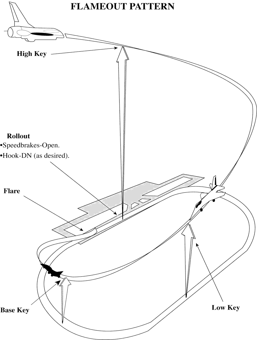
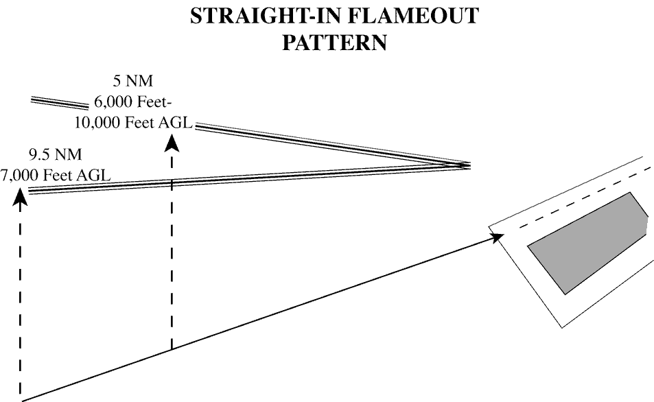
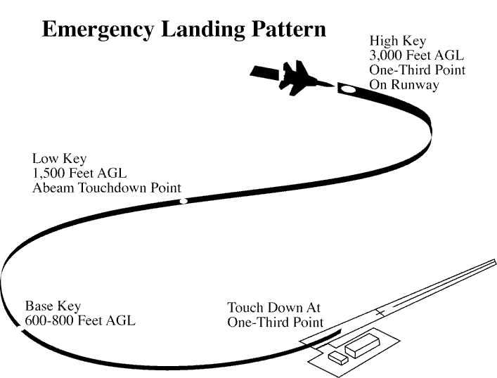
Section 11. Helicopter Operations
3-11-1. TAXI AND GROUND MOVEMENT OPERATION
- When necessary for a wheeled helicopter to taxi on the surface, use the phraseology in para 3-7-2, Taxi and Ground Movement Operations.
NOTE: Ground taxiing uses less fuel than hover-taxiing and minimizes air turbulence. However, under certain conditions, such as rough, soft, or uneven terrain, it may become necessary to hover/air-taxi for safety considerations. Helicopters with articulating rotors (usually designs with three or more main rotor blades) are subject to “ground resonance” and may, on rare occasions, suddenly lift off the ground to avoid severe damage or destruction.
- When requested or necessary for a helicopter/VTOL aircraft to proceed at a slow speed above the surface, normally below 20 knots and in ground effect, use the following phraseology, supplemented as appropriate with the phraseology in para 3-7-2, Taxi and Ground Movement Operations.
- PHRASEOLOGY
- HOVER-TAXI (supplemented, as appropriate, from para 3-7-2, Taxi and Ground Movement Operations.)
- CAUTION (dust, blowing snow, loose debris, taxiing light aircraft, personnel, etc.).
NOTE: Hover-taxiing consumes fuel at a high burn rate, and helicopter downwash turbulence (produced in ground effect) increases significantly with larger and heavier helicopters.
- When requested or necessary for a helicopter to proceed expeditiously from one point to another, normally below 100 feet AGL and at airspeeds above 20 knots, use the following phraseology, supplemented as appropriate with the phraseology in para 3-7-2, Taxi and Ground Movement Operations.
- PHRASEOLOGY
- AIR-TAXI:
- VIA (direct, as requested, or specified route)
- TO (location, heliport, helipad, operating/movement area, active/inactive runway).
- AVOID (aircraft/vehicles/personnel). If required,
- REMAIN AT OR BELOW (altitude).
- CAUTION (wake turbulence or other reasons above). LAND AND CONTACT TOWER,
- or
- HOLD FOR (reason- takeoff clearance, release, landing/taxiing aircraft, etc.).
NOTE: Air-taxi is the preferred method for helicopter movements on airports provided ground operations/conditions permit. Air-taxi authorizes the pilot to proceed above the surface either via hover-taxi or flight at speeds more than 20 knots. Unless otherwise requested or instructed, the pilot is expected to remain below 100 feet AGL. The pilot is solely responsible for selecting a safe airspeed for the altitude/operation being conducted.
WAKE TURBULENCE APPLICATION
- Avoid clearances which require small aircraft or helicopters to taxi in close proximity to taxiing or hover-taxi helicopters.
3-11-2. HELICOPTER TAKEOFF CLEARANCE
- Issue takeoff clearances from movement areas other than active runways or in diverse directions from active runways, with additional instructions as necessary. Whenever possible, issue takeoff clearance in lieu of extended hover-taxi or air-taxi operations.
- PHRASEOLOGY
- (Present position, taxiway, helipad, numbers) MAKE RIGHT/LEFT TURN FOR (direction, points of compass, heading, NAVAID radial) DEPARTURE/DEPARTURE ROUTE (number, name, or code), AVOID (aircraft/ vehicles/personnel),
- or
- REMAIN (direction) OF (active runways, parking areas, passenger terminals, etc.).
- CAUTION (power lines, unlighted obstructions, trees, wake turbulence, etc.).
- CLEARED FOR TAKEOFF.
- If takeoff is requested from non-movement areas, an area not authorized for helicopter use, or an area off the airport, and, in your judgment, the operation appears to be reasonable, use the following phraseology instead of the takeoff clearance in subpara a.
- PHRASEOLOGY
- DEPARTURE FROM (requested location) WILL BE AT YOUR OWN RISK (additional instructions, as necessary). USE CAUTION (if applicable).
- Unless agreed to by the pilot, do not issue downwind takeoffs if the tailwind exceeds 5 knots.
NOTE: A pilot request to takeoff from a given point in a given direction constitutes agreement.
3-11-3. HELICOPTER DEPARTURE SEPARATION
Separate a departing helicopter from other helicopters by ensuring that it does not takeoff until one of the following conditions exists:
NOTE: Helicopters performing air-taxiing operations within the boundary of the airport are considered to be taxiing aircraft.
- A preceding, departing helicopter has left the takeoff area. (See FIG 3-11-1.)
FIG 3-11-1 Helicopter Departure Separation 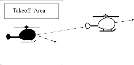
- A preceding, arriving helicopter has taxied off the landing area. (See FIG 3-11-2.)
FIG 3-11-2 Helicopter Departure Separation 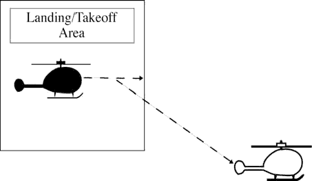
3-11-4. HELICOPTER ARRIVAL SEPARATION
Separate an arriving helicopter from other helicopters by ensuring that it does not land until one of the following conditions exists:
- A preceding, arriving helicopter has come to a stop or taxied off the landing area.
(See FIG 3-11-3 and FIG 3-11-4.)
FIG 3-11-3 Helicopter Arrival Separation 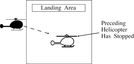
FIG 3-11-4 Helicopter Arrival Separation 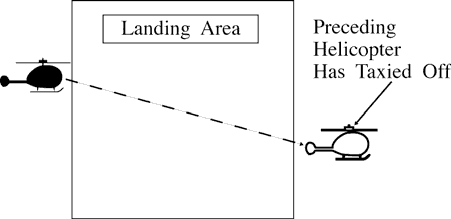
- A preceding, departing helicopter has left the landing area. (See FIG 3-11-5.)
FIG 3-11-5 Helicopter Arrival Separation 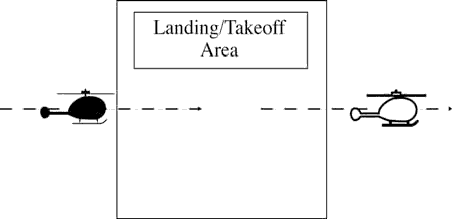
3-11-5. SIMULTANEOUS LANDINGS OR TAKEOFFS
Authorize helicopters to conduct simultaneous landings or takeoffs if the distance between the landing or takeoff points is at least 200 feet and the courses to be flown do not conflict. Refer to surface markings to determine the 200 foot minimum, or instruct a helicopter to remain at least 200 feet from another helicopter. (See FIG 3-11-6.)
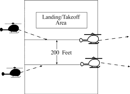
3-11-6. HELICOPTER LANDING CLEARANCE
- Issue landing clearances to helicopters going to movement areas other than active runways or from diverse directions to points on active runways, with additional instructions as necessary. Whenever possible, issue a landing clearance in lieu of extended hover-taxi or air-taxi operations.
- PHRASEOLOGY
- MAKE APPROACH STRAIGHT-IN/CIRCLING LEFT/ RIGHT TURN TO (location, runway, taxiway, helipad, Maltese cross) ARRIVAL/ARRIVAL ROUTE (number, name, or code).
- HOLD SHORT OF (active runway, extended runway centerline, other).
- REMAIN (direction/distance; e.g., 700 feet, 1 1/2 miles) OF/FROM (runway, runway centerline, other helicopter/ aircraft).
- CAUTION (power lines, unlighted obstructions, wake turbulence, etc.).
- CLEARED TO LAND.
- If landing is requested to non-movement areas, an area not authorized for helicopter use, or an area off the airport, and, in your judgment, the operation appears to be reasonable, use the following phraseology instead of the landing clearance in subpara a.
- PHRASEOLOGY
- LANDING AT (requested location) WILL BE AT YOUR OWN RISK (additional instructions, as necessary). USE CAUTION (if applicable).
- Unless agreed to by the pilot, do not issue downwind landings if the tailwind exceeds 5 knots.
NOTE: A pilot request to land at a given point from a given direction constitutes agreement.
Section 12. Sea Lane Operations
3-12-1. APPLICATION
Where sea lanes are established and controlled, apply the provisions of this section.
3-12-2. DEPARTURE SEPARATION
Separate a departing aircraft from a preceding departing or arriving aircraft using the same sea lane by ensuring that it does not commence takeoff until:
- The other aircraft has departed and crossed the end of the sea lane or turned to avert any conflict. (See FIG 3-12-1). If you can determine distances by reference to suitable landmarks, the other aircraft need only be airborne if the following minimum distance exists between aircraft:
- When only Category I aircraft are involved- 1,500 feet.
- When a Category I aircraft is preceded by a Category II aircraft- 3,000 feet.
- When either the succeeding or both are Category II aircraft- 3,000 feet.
- When either is a Category III aircraft- 6,000 feet. (See FIG 3-12-2.)
FIG 3-12-1 Sea Lane Departure Operations 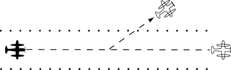
FIG 3-12-2 Sea Lane Departure Operations 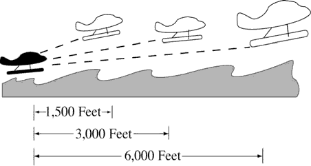
- A preceding landing aircraft has taxied out of the sea lane.
NOTE: Due to the absence of braking capability, caution should be exercised when instructing a float plane to hold a position as the aircraft will continue to move because of prop generated thrust. Therefore, clearance to line up and wait should be followed by takeoff or other clearance as soon as is practical.
3-12-3. ARRIVAL SEPARATION
Separate an arriving aircraft from another aircraft using the same sea lane by ensuring that the arriving aircraft does not cross the landing threshold until one of the following conditions exists:
- The other aircraft has landed and taxied out of the sea lane. Between sunrise and sunset, if you can determine distances by reference to suitable landmarks and the other aircraft has landed, it need not be clear of the sea lane if the following minimum distance from the landing threshold exists:
- When a Category I aircraft is landing behind a Category I or II- 2,000 feet. (See FIG 3-12-3.)
FIG 3-12-3 Sea Lane Arrival Operations 
- When a Category II aircraft is landing behind a Category I or II- 2,500 feet. (See FIG 3-12-4.)
FIG 3-12-4 Sea Lane Arrival Operations [View 2] 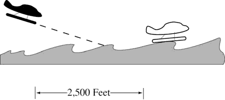
- When a Category I aircraft is landing behind a Category I or II- 2,000 feet. (See FIG 3-12-3.)
- The other aircraft has departed and crossed the end of the sea lane or turned to avert any conflict. (See FIG 3-12-5.) If you can determine distances by reference to suitable landmarks and the other aircraft is airborne, it need not have crossed the end of the sea lane if the following minimum distance from the landing threshold exists:
- When only Category I aircraft are involved- 1,500 feet.
- When either is a Category II aircraft- 3,000 feet.
- When either is a Category III aircraft- 6,000 feet. (See FIG 3-12-6.)
FIG 3-12-5 Sea Lane Arrival Operations 
FIG 3-12-6 Sea Lane Arrival Operations