Section 1. General
5-1-1. PRESENTATION AND EQUIPMENT PERFORMANCE
-
Provide radar services only if you are personally satisfied that the radar presentation and equipment performance
is adequate for the service being provided.
NOTE: The provision of radar services is not limited to the distance and altitude parameters obtained during the commissioning flight check. FAA Order 8200.1, United States Standard Flight Inspection Manual, Chapter 14, Surveillance, describes the surveillance flight inspection procedures.
- Notify the OS/CIC of any radar malfunctions or unexpected outages. Advise adjacent facilities when appropriate.
- REFERENCE
- FAA Order JO 7110.65, Para 2-1-9, Reporting Essential Flight Information.
- FAA Order JO 7210.3, Chapter 3, Chapter 7, Chapter 10 Section 5, and Chapter 12 section 6.
5-1-2. ATC SURVEILLANCE SOURCE USE
Use approved ATC Surveillance Sources.
-
Secondary radar may be used as the sole display source as follows:
- In Class A airspace.
- REFERENCE
- FAA Order JO 7110.65, Para 5-2-14, Failed Transponder in Class A Airspace.
- 14 CFR Section 91.135, Operations in Class A Airspace.
-
Outside Class A airspace, or where mix of Class A airspace/non-Class A airspace exists, only when:
- (a) Additional coverage is provided by secondary radar beyond that of the primary radar, or
-
(b) The primary radar is temporarily unusable or out of service. Advise pilots when these conditions
exist, or
- PHRASEOLOGY
- PRIMARY RADAR UNAVAILABLE (describe location). RADAR SERVICES AVAILABLE ON TRANSPONDER OR ADS-B EQUIPPED AIRCRAFT ONLY.
- NOTE:
- 1. Advisory may be omitted when provided on ATIS and pilot indicates having ATIS information.
- 2. This provision is to authorize secondary radar only operations where there is no primary radar available and the condition is temporary.
-
(c) A secondary radar system is the only source of radar data for the area of service. TERMINAL. Advise pilots when these
conditions exist.
NOTE: Advisory may be omitted when provided on ATIS or by other appropriate notice to pilots.
- TERMINAL. Do not use secondary radar only to conduct surveillance (ASR) final approaches unless an emergency exists and the pilot concurs.
- All procedures and requirements relating to ATC services using secondary radar targets apply to ATC services provided to targets derived from ADS-B and WAM.
-
Targets derived from ADS-B and WAM may be used for the provision of all terminal services when operating in STARS
Fusion, STARS FMA, and STARS Multi-Sensor Mode, including those associated with any published instrument procedure
annotated "radar required."
NOTE: Targets derived from WAM cannot be used to provide 3NM separation in the EAS. 3NM targets are not derived from WAM within the EAS.
- REFERENCE
- FAA Order JO 7110.65, Para 4-1-2, Exceptions.
- FAA Order JO 7110.65, Para 4-4-2, Route Structure Transitions.
- FAA Order JO 7110.65, Para 5-5-1, Application.
- FAA Order JO 7110.65, Para 6-5-4, Minima Along Other Than Established Airways or Routes.
- FAA Order JO 7110.65, Chapter 6, Nonradar.
- FAA Order JO 7110.65, Para 5-5-4, Minima.
- FAA Order JO 7210.3, Para 3-6-2, ATC Surveillance Source Use.
5-1-3. ELECTRONIC ATTACK (EA) ACTIVITY
-
Refer all EA activity requests to the appropriate center supervisor.
- REFERENCE
- FAA Order JO 7610.4, Chapter 2, Section 7, Electronic Attack (EA) and Testing Coordination.
NOTE: EA activity can subsequently result in a request to apply EA videos to the radar system which may necessitate the decertification of the narrow band search radar. The Systems Engineer should be consulted concerning the effect of EA on the operational use of the narrow band radar prior to approving/disapproving requests to conduct EA activity.
-
When EA activity interferes with the operational use of radar:
- EN ROUTE. Request the responsible military unit or aircraft, if initial request was received directly from pilot, to suspend the activity.
- TERMINAL. Request suspension of the activity through the ARTCC. If immediate cessation of the activity is required, broadcast the request directly to the EA aircraft on the emergency frequency. Notify the ARTCC of direct broadcast as soon as possible.
-
When previously suspended activity will no longer interfere:
- EN ROUTE. Inform the NORAD unit or aircraft that it may be resumed.
- TERMINAL. Inform the ARTCC or aircraft that it may be resumed. Obtain approval from the ARTCC prior to broadcasting a resume clearance directly to the aircraft.
-
In each stop request, include your facility name, type of EA activity (chaff dispensing- “stream”/“burst” or
electronic jamming- “buzzer”), radar band affected and, when feasible, expected duration of suspension.
- PHRASEOLOGY
- BIG PHOTO (identification, if known) (name) CENTER/TOWER/APPROACH CONTROL.
- To stop EA activity:
- STOP STREAM/BURST IN AREA (area name) (degree and distance from facility),
- or
- STOP BUZZER ON (frequency band or channel).
- To resume EA activity:
- RESUME STREAM/BURST,
- or
- RESUME BUZZER ON (frequency band or channel).
5-1-4. MERGING TARGET PROCEDURES
-
Except while they are established in a holding pattern, apply merging target procedures to all radar identified:
- Aircraft at 10,000 feet and above.
-
Turbojet aircraft regardless of altitude.
- REFERENCE
- P/CG Term - Turbojet Aircraft.
- Presidential aircraft regardless of altitude.
-
Issue traffic information to the aircraft listed in subparagraph a whose targets appear likely to merge unless
the
aircraft are separated by more than the appropriate vertical separation minima.
- EXAMPLE
- “Traffic twelve o'clock, seven miles, eastbound, Gulfstream 650, one seven thousand.”
- “United Sixteen and American Twenty-Five, traffic twelve o'clock, one zero miles, opposite direction, eastbound Seven Thirty-Seven at flight level three three zero, westbound Airbus Three Twenty at flight level three two zero.”
-
When both aircraft in subparagraph b are in RVSM airspace, and vertically separated by 1,000 feet, and either
pilot
reports they are unable to maintain RVSM due to turbulence or mountain wave, use vectors to prevent the targets
from merging.
- EXAMPLE
- “Delta One Twenty Three, fly heading two niner zero, vector for traffic. Traffic twelve o'clock, one zero miles, opposite direction, Seven Thirty-Seven, eastbound at flight level three one zero.”
-
If the pilot requests, vector their aircraft to avoid merging targets with the previously issued traffic.
NOTE: Because aircraft closure rates can be rapid, issue traffic with enough time for the pilot to decide if a vector is necessary.
-
If unable to provide vector service, inform the pilot.
NOTE: The phraseology “Unable RVSM due turbulence (or mountain wave)” is only intended for severe turbulence or other weather encounters with altitude deviations of approximately 200 feet or more.
5-1-5. HOLDING PATTERN SURVEILLANCE
Provide radar surveillance of outer fix holding pattern airspace areas, or any portions thereof, shown on your radar scope (displayed on the video map or scribed on the map overlay) whenever aircraft are holding there. Attempt to detect any aircraft that stray outside the area. If you detect an aircraft straying outside the area, assist it to return to the assigned airspace.
5-1-6. DEVIATION ADVISORIES
Inform an aircraft when it is observed in a position and on a track which will obviously cause the aircraft to deviate from its protected airspace area. If necessary, help the aircraft to return to the assigned protected airspace.
- NOTE:
- 1. RNAV ATS routes have a width of 8 miles and laterally protected airspace of 4 miles on each side of the route centerline
- 2. Navigation system performance requirements for operations on RNAV ATS routes require the aircraft system be capable of remaining within 2 miles of the route centerline. Aircraft approaching this limit may be experiencing a navigation system error or failure.
- REFERENCE
- FAA Order JO 7110.65, Para 4-2-5, Route or Altitude Amendments.
- FAA Order JO 7110.65, Para 7-9-3, Methods.
- FAA Order 7400.2, Para 20-5-2. RNAV Route Criteria.
- AC90-100A, U.S. Terminal and En Route Area Navigation (RNAV) Operations, Para 8a. Navigation System Accuracy
5-1-7. MANUAL FIX POSTING
EN ROUTE
Manually record the observed or reported time over a fix at least once for each controlled aircraft in your sector of responsibility when the flight progress recording components of the EAS FDP are not operational.
- REFERENCE
- FAA Order JO 7210.3, Para 6-1-6, Flight Progress Strip Usage.
5-1-8. POSITION REPORTING
If necessary, you may request an aircraft to provide an estimate or report over a specific fix. After an aircraft receives the statement “radar contact” from ATC, it discontinues reporting over compulsory reporting points. It resumes normal position reporting when ATC informs it “radar contact lost” or “radar service terminated.”
- REFERENCE
- P/CG Term - Radar Contact.
-
When required, inform an aircraft of its position with respect to a fix or airway.
- PHRASEOLOGY
- OVER/PASSING (fix).
- (Number of miles) MILES FROM (fix).
- (Number of miles) MILES (direction) OF (fix, airway, or location).
- CROSSING/JOINING/DEPARTING (airway or route).
- INTERCEPTING/CROSSING (name of NAVAID) (specified) RADIAL.
5-1-9. RADAR SERVICE TERMINATION
-
Inform aircraft when radar service is terminated.
- PHRASEOLOGY
- RADAR SERVICE TERMINATED (nonradar routing if required).
-
Radar service is automatically terminated and the aircraft needs not be advised of termination when:
NOTE: Termination of radar monitoring when conducting simultaneous ILS approaches is prescribed in paragraph 5-9-7, Simultaneous Independent Approaches- Dual Triple.
- An aircraft cancels its IFR flight plan, except within Class B airspace, Class C airspace, TRSA, or where basic radar service is provided.
- An aircraft conducting an instrument, visual, or contact approach has landed or has been instructed to change to advisory frequency.
-
At tower-controlled airports where radar coverage does not exist to within 1/2 mile of the end of the runway,
arriving aircraft must be informed when radar service is terminated.
- REFERENCE
- FAA Order JO 7210.3, Para 10-5-6, Radar Tolerances.
- TERMINAL. An arriving VFR aircraft receiving radar service to a tower-controlled airport within Class B airspace, Class C airspace, TRSA, or where basic radar service is provided has landed, or to all other airports, is instructed to change to tower or advisory frequency.
- TERMINAL. An aircraft completes a radar approach.
Section 2. Beacon/ADS-B Systems
5-2-1. ASSIGNMENT CRITERIA
-
General.
- Mode 3/A is designated as the common military/civil mode for air traffic control use.
-
Make beacon code assignments to only ADS-B and/or transponder-equipped aircraft.
NOTE: Aircraft equipped with ADS-B are also still required to have an operable transponder. The ATC-assigned beacon code is one of the required message elements of ADS-B Out.
-
Unless otherwise specified in this section, a facility directive, or a letter of agreement, issue beacon codes
assigned by the computer. Computer assigned codes may be modified as required.
NOTE: The computer will assign only discrete beacon codes unless all the discrete codes allocated to a facility are in use.
- TERMINAL. Aircraft that will remain within the terminal facility's delegated airspace must be assigned a code from the code subset allocated to the terminal facility.
-
TERMINAL. Unless otherwise specified in a facility directive or a letter of
agreement, aircraft that will enter an adjacent facility's delegated airspace must be assigned a beacon code
assigned by the ARTCC computer.
NOTE: This will provide the adjacent facility advance information on the aircraft and will cause auto-acquisition of the aircraft prior to handoff. When an airborne aircraft that has been assigned a beacon code by the ARTCC computer and whose flight plan will terminate in another facility's area cancels ATC service, appropriate action should be taken to remove flight plan information on that aircraft.
- PHRASEOLOGY
- SQUAWK THREE/ALFA (code),
- or
- SQUAWK (code).
-
Code 4000 should be assigned when aircraft are operating on a flight plan specifying frequent or rapid changes in
assigned altitude in more than one stratum or other category of flight not compatible with a discrete code
assignment.
- NOTE:
- 1. Categories of flight that can be assigned Code 4000 include certain flight test aircraft, MTR missions, aerial refueling operation requiring descent involving more than one stratum, ALTRVs where continuous monitoring of ATC frequencies is not required and frequent altitude changes are approved, and other flights requiring special handling by ATC.
- 2. Military aircraft operating in restricted/warning areas or on VR routes will squawk 4000 unless another code has been assigned or coordinated with ATC.
5-2-2. RADAR BEACON CODE CHANGES
Unless otherwise specified in a directive or a letter of agreement or coordinated at the time of handoff, do not request an aircraft to change from the code it was squawking in the transferring facility's area until the aircraft is within your area of responsibility.
5-2-3. EMERGENCY CODE ASSIGNMENT
Assign codes to emergency aircraft as follows:
-
Code 7700 when the pilot declares an emergency and the aircraft is not radar identified.
- PHRASEOLOGY
- SQUAWK MAYDAY ON 7700.
NOTE: Instead of displaying “7700” in the data block, ERAM will display “EMRG,” and STARS/MEARTS will display “EM.”
-
After radio and radar contact have been established, you may request other than single-piloted helicopters and
single-piloted turbojet aircraft to change from Code 7700 Code 7700 to a computer-assigned
discrete code.
- NOTE:
- 1. The code change, based on pilot concurrence, the nature of the emergency, and current flight conditions will signify to other ATC facilities that the aircraft in distress is identified and under ATC control.
- 2. Pilots of single-piloted helicopters and single-piloted turbojet aircraft may be unable to change transponder settings during an emergency.
- PHRASEOLOGY
- RADAR CONTACT (position). IF FEASIBLE, SQUAWK (code).
-
The following must be accomplished on a Mode C equipped VFR aircraft which is in emergency but no longer requires
the assignment of Code 7700:
- TERMINAL. Assign a beacon code that will permit terminal minimum safe altitude warning (MSAW) alarm processing.
- EN ROUTE. An appropriate keyboard entry must be made to ensure en route MSAW (EMSAW) alarm processing.
5-2-4. RADIO FAILURE
When you observe a Code 7600 display, apply the procedures in para 10-4-4, Communications Failure.
- NOTE:
- 1. An aircraft experiencing a loss of two-way radio communications capability can be expected to squawk Code 7600.
- 2. Instead of displaying “7600” in the data block, ERAM will display “RDOF,” and STARS/MEARTS will display “RF.”
5-2-5. HIJACK/UNLAWFUL INTERFERENCE
When you observe a Code 7500 display, apply the procedures in paragraph 10-2-6, Hijacked Aircraft.
NOTE: Instead of displaying “7500” in the data block, ERAM will display “HIJK,” and STARS/MEARTS will display “HJ.”
5-2-6. UNMANNED AIRCRAFT SYSTEMS (UAS) LOST LINK
Code 7400 may be transmitted by unmanned aircraft systems (UAS) when the control link between the aircraft and the pilot is lost. Lost link procedures are programmed into the flight management system and associated with the flight plan being flown.
When you observe a Code 7400 display, do the following:
NOTE: Instead of displaying “7400” in the data block, ERAM will display “LLNK,” and STARS/MEARTS will display “LL.”
- Determine the lost link procedure,as outlined in the Special Airworthiness Certificate or Certificate of Waiver or Authorization (COA).
- Coordinate, as required, to allow UAS to execute the lost link procedure.
- Advise the OS/CIC, when feasible, so the event can be documented.
- If you observe or are informed by the PIC that the UAS is deviating from the programmed Lost Link procedure, or is encountering another anomaly, treat the situation in accordance with FAA Order J0 7110.65 Chapter 10, Section 1, Para 10-1-1(c).
- NOTE
- 1. The available lost link procedure should, at a minimum, include lost link route of flight, lost link orbit points, lost link altitudes, communications procedures and preplanned flight termination points if the event recovery of the UAS is deemed unfeasible.
- 2. Each lost link procedure may differ and is dependent upon airframe and operation. These items are contained in the flight's Certificate of Authorization or Waiver (COA) and must be made available to ATC personnel in their simplest form at positions responsible for Unmanned Aircraft (UAs).
- 3. Some UA airframes (Global Hawk) will not be programmed upon the NAS Automation roll out to squawk 7400. These airframes will continue to squawk 7600 should a lost link occur. The ATC Specialist must apply the same procedures described above.
5-2-7. VFR CODE ASSIGNMENTS
-
For VFR aircraft receiving radar advisories, issue a computer-assigned beacon code.
-
If the aircraft is outside of your area of responsibility and an operational benefit will be gained by
retaining the aircraft on your frequency for the purpose of providing services, ensure that coordination has
been effected:
- (a) As soon as possible after positive identification, and
- (b) Prior to issuing a control instruction or providing a service other than a safety alert/traffic advisory.
NOTE: Safety alerts/traffic advisories may be issued to an aircraft prior to coordination if an imminent situation may be averted by such action. Coordination should be effected as soon as possible thereafter.
-
If the aircraft is outside of your area of responsibility and an operational benefit will be gained by
retaining the aircraft on your frequency for the purpose of providing services, ensure that coordination has
been effected:
-
Instruct an IFR aircraft that cancels its IFR flight plan and is not requesting radar advisory service, or a VFR
aircraft for which radar advisory service is being terminated, to squawk VFR.
- PHRASEOLOGY
- SQUAWK VFR.
- or
- SQUAWK 1200.
- NOTE:
- 1. Aircraft not in contact with ATC may squawk 1255 in lieu of 1200 while en route to/from or within designated firefighting areas.
- 2. VFR aircraft which fly authorized SAR missions for the USAF or USCG may be advised to squawk 1277 in lieu of 1200 while en route to/from or within the designated search area.
- 3. VFR gliders should squawk 1202 in lieu of 1200. Gliders operate under some flight and maneuvering limitations. They may go from essentially stationary targets while climbing and thermaling to moving targets very quickly. They can be expected to make radical changes in flight direction to find lift and cannot hold altitude in a response to an ATC request. Gliders may congregate together for short periods of time to climb together in thermals and may cruise together in loose formations while traveling between thermals.
- 4. The lead aircraft in a s tandard VFR formation flight not in contact with ATC should squawk 1203 in lieu of 1200. All other aircraft in the formation should squawk standby.
- REFERENCE
- FAA Order JO 7110.66, National Beacon Code Allocation Plan.
- When an aircraft changes from VFR to IFR, assign a beacon code to Mode C equipped aircraft that will allow MSAW alarms.
5-2-8. BEACON CODE FOR PRESSURE SUIT FLIGHTS AND FLIGHTS ABOVE FL600
Special use Mode 3/A codes are reserved for certain pressure suit flights and aircraft operations above FL 600 in accordance with FAA Order JO 7610.4, Special Operations.
- Ensure that these flights remain on one of the special use codes if filed in the flight plan, except:
- When unforeseen events cause more than one aircraft to be in the same or adjacent ARTCC's airspace at the same time on the same special use discrete code, if necessary, you may request the pilot to make a code change, squawk standby, or stop squawk as appropriate.
- NOTE:
- 1. Current FAA automation systems track multiple targets on the same beacon code with much greater reliability than their predecessors, and a code change may not be necessary for such flights.
- 2. The beacon code is often preset on the ground for such flights and is used throughout the flight profile, including operations below FL 600. Due to equipment inaccessibility, the flight crew may not be able to accept transponder changes identified in this subparagraph.
- 3. In case of emergency, Code 7700 can still be activated. Instead of displaying “7700” in the data block, ERAM will display “EMRG,” and STARS/MEARTS will display “EM.”
5-2-9. AIR DEFENSE EXERCISE BEACON CODE ASSIGNMENT
EN ROUTE
Ensure exercise FAKER aircraft remain on the exercise flight plan filed discrete beacon code.
- NOTE:
- 1. NORAD will ensure exercise FAKER aircraft flight plans are filed containing discrete beacon codes from the Department of Defense code allocation specified in FAA Order JO 7610.4, Special Operations, Appendix 6.
- 2. NORAD will ensure that those FAKER aircraft assigned the same discrete beacon code are not flight planned in the same or any adjacent ARTCC's airspace at the same time. (Simultaneous assignment of codes will only occur when operational requirements necessitate.)
5-2-10. STANDBY OPERATION
You may instruct an aircraft operating on an assigned code to change transponder/ADS-B to “standby” position:
- When approximately 15 miles from its destination and you no longer desire operation of the transponder/ADS-B; or
- When necessary to reduce clutter in a multi-target area, provided you instruct the pilot to return the transponder/ADS-B to “normal” position as soon as possible thereafter.
- PHRASEOLOGY
- SQUAWK STANDBY,
- or
- SQUAWK NORMAL.
5-2-11. CODE MONITOR
interpretation 20- Continuously monitor the codes assigned to aircraft operating within your area of responsibility. Additionally, monitor Code 1200, Code 1202, Code 1255, and Code 1277 unless your area of responsibility includes only Class A airspace. During periods when ring-around or excessive VFR target presentations derogate the separation of IFR traffic, the monitoring of VFR Code 1200, Code 1202, Code 1255, and Code 1277 may be temporarily discontinued.
- When your area of responsibility contains or is immediately adjacent to a restricted area, warning area, VR route, or other category where Code 4000 is appropriate, monitor Code 4000 and any other code used in lieu of 4000.
- REFERENCE
- FAA Order JO 7210.3, Para 3-6-3, Monitoring of Mode 3/A Radar Beacon Codes.
5-2-12. FAILURE TO DISPLAY ASSIGNED BEACON CODE OR INOPERATIVE/MALFUNCTIONING TRANSPONDER
-
Inform an aircraft with an operable transponder that the assigned beacon code is not being displayed.
- PHRASEOLOGY
- (Identification) RESET TRANSPONDER, SQUAWK (appropriate code).
-
Inform an aircraft when its transponder appears to be inoperative or malfunctioning.
- PHRASEOLOGY
- (Identification) YOUR TRANSPONDER APPEARS INOPERATIVE/MALFUNCTIONING, RESET, SQUAWK (appropriate code).
- Ensure that the subsequent control position in the facility or the next facility, as applicable, is notified when an aircraft transponder is malfunctioning/inoperative.
5-2-13. INOPERATIVE OR MALFUNCTIONING INTERROGATOR
Inform aircraft concerned when the ground interrogator appears to be inoperative or malfunctioning.
- PHRASEOLOGY
- (Name of facility or control function) BEACON INTERROGATOR INOPERATIVE/MALFUNCTIONING.
5-2-14. FAILED TRANSPONDER OR ADS-B OUT TRANSMITTER
Disapprove a request or withdraw a previously issued approval to operate with a failed transponder or ADS-B Out solely on the basis of traffic conditions or other operational factors.
5-2-15. VALIDATION OF MODE C READOUT
Ensure that Mode C altitude readouts are valid after accepting an interfacility handoff, initial track start, track start from coast/suspend tabular list, or during and after an unreliable Mode C readout, except as follows:
NOTE: Consider a Mode C readout unreliable when any condition, not just those that display an indicator in the Data Block, exists that indicates that the Mode C may be in error.
- CTRD-equipped tower cabs are not required to validate Mode C altitude readouts after accepting interfacility handoffs from TRACONs according to the procedures in Paragraph 5-4-3, Methods, subparagraph a4.
-
ERAM facilities are not required to validate Mode C altitude readouts after accepting interfacility handoffs from
other ERAM facilities, except:
- After initial track start or track start from coast is required, or
- During and after the display of a missing, unreasonable, exceptional, or otherwise unreliable Mode C readout indicator.
-
Consider an altitude readout valid when:
-
It varies less than 300 feet from the pilot reported altitude, or
- PHRASEOLOGY
- (If aircraft is known to be operating below the lowest usable flight level),
- SAY ALTITUDE.
- or
- (If aircraft is known to be operating at or above the lowest usable flight level),
- SAY FLIGHT LEVEL.
-
You receive a continuous readout from an aircraft on the airport and the readout varies by less than 300 feet
from the field elevation, or
NOTE: A continuous readout exists only when the altitude filter limits are set to include the field elevation.
- You have correlated the altitude information in your data block with the validated information in a data block generated in another facility (by verbally coordinating with the other controller) and your readout is exactly the same as the readout in the other data block.
-
It varies less than 300 feet from the pilot reported altitude, or
- When unable to validate the read out, do not use the Mode C altitude information for separation.
-
Whenever you observe an invalid Mode C readout below FL 180:
-
Issue the correct altimeter setting and confirm the pilot has accurately reported the altitude.
- PHRASEOLOGY
- (Location) ALTIMETER (appropriate altimeter), VERIFY ALTITUDE.
-
If the altitude readout continues to be invalid:
- (a) Instruct the pilot to turn off the altitude reporting part of his/her transponder and include the reason; and
- (b) Notify the operations supervisor-in-charge of the aircraft call sign.
- PHRASEOLOGY
- STOP ALTITUDE SQUAWK. ALTITUDE DIFFERS BY (number of feet) FEET.
-
Issue the correct altimeter setting and confirm the pilot has accurately reported the altitude.
-
Whenever you observe an invalid Mode C readout at or above FL 180, unless the aircraft is descending below Class A
airspace:
-
Verify that the pilot is using 29.92 inches of mercury as the altimeter setting and has accurately reported
the altitude.
- PHRASEOLOGY
- VERIFY USING TWO NINER NINER TWO AS YOUR ALTIMETER SETTING.
- (If aircraft is known to be operating at or above the lowest usable flight level),
- VERIFY FLIGHT LEVEL.
-
If the Mode C readout continues to be invalid:
- (a) Instruct the pilot to turn off the altitude reporting part of his/her transponder and include the reason; and
- (b) Notify the operations supervisor-in-charge of the aircraft call sign.
- PHRASEOLOGY
- STOP ALTITUDE SQUAWK. ALTITUDE DIFFERS BY (number of feet) FEET.
-
Verify that the pilot is using 29.92 inches of mercury as the altimeter setting and has accurately reported
the altitude.
- Whenever possible, inhibit altitude readouts on all consoles when a malfunction of the ground equipment causes repeated invalid readouts.
5-2-16. ALTITUDE CONFIRMATION - MODE C
Request a pilot to confirm assigned altitude on initial contact unless:
NOTE: For the purpose of this paragraph, “initial contact” means a pilot's first radio contact with each sector/position.
- The pilot states the assigned altitude, or
- You assign a new altitude to a climbing or a descending aircraft, or
- The Mode C readout is valid and indicates that the aircraft is established at the assigned altitude, or
-
TERMINAL. The aircraft was transferred to you from another sector/position within
your facility (intrafacility).
- PHRASEOLOGY
- (In level flight situations), VERIFY AT (altitude/flight level).
- (In climbing/descending situations),
- (if aircraft has been assigned an altitude below the lowest usable flight level),
- VERIFY ASSIGNED ALTITUDE (altitude).
- or
- (If aircraft has been assigned a flight level at or above the lowest usable flight level),
- VERIFY ASSIGNED FLIGHT LEVEL (flight level).
5-2-17. ALTITUDE CONFIRMATION - NON-MODE C
-
Request a pilot to confirm assigned altitude on initial contact unless:
NOTE: For the purpose of this paragraph, “initial contact” means a pilot's first radio contact with each sector/position.
- The pilot states the assigned altitude, or
- You assign a new altitude to a climbing or a descending aircraft, or
- TERMINAL. The aircraft was transferred to you from another sector/position within your facility (intrafacility).
- PHRASEOLOGY
- (In level flight situations), VERIFY AT (altitude/flight level).
- (In climbing/descending situations), VERIFY ASSIGNED ALTITUDE/FLIGHT LEVEL (altitude/flight level).
-
USA. Reconfirm all pilot altitude read backs.
- PHRASEOLOGY
- (If the altitude read back is correct),
- AFFIRMATIVE (altitude).
- (If the altitude read back is not correct),
- NEGATIVE. CLIMB/DESCEND AND MAINTAIN (altitude),
- or
- NEGATIVE. MAINTAIN (altitude).
5-2-18. AUTOMATIC ALTITUDE REPORTING
Inform an aircraft when you want it to turn on/off the automatic altitude reporting feature of its transponder.
- PHRASEOLOGY
- SQUAWK ALTITUDE,
- or
- STOP ALTITUDE SQUAWK.
NOTE: Controllers should be aware that not all aircraft have a capability to disengage the altitude squawk independently from the beacon code squawk. On some aircraft both functions are controlled by the same switch.
5-2-19. INFLIGHT DEVIATIONS FROM TRANSPONDER/MODE C REQUIREMENTS BETWEEN 10,000 FEET AND 18,000 FEET
Apply the following procedures to requests to deviate from the Mode C transponder requirement by aircraft operating in the airspace of the 48 contiguous states and the District of Columbia at and above 10,000 feet MSL and below 18,000 feet MSL, excluding the airspace at and below 2,500 feet AGL.
- NOTE:
- 1. 14 CFR Section 91.215 (b) provides, in part, that all U.S. registered civil aircraft must be equipped with an operable, coded radar beacon transponder when operating in the altitude stratum listed above. Such transponders must have a Mode 3/A 4096 code capability, replying to Mode 3/A interrogation with the code specified by ATC, or a Mode S capability, replying to Mode 3/A interrogations with the code specified by ATC. The aircraft must also be equipped with automatic pressure altitude reporting equipment having a Mode C capability that automatically replies to Mode C interrogations by transmitting pressure altitude information in 100-foot increments.
- 2. The exception to 14 CFR Section 91.215 (b) is 14 CFR Section 91.215(b)(5) which states: except balloons, gliders, and aircraft without engine-driven electrical systems.
- REFERENCE
- FAA Order JO 7210.3, Chapter 20, Temporary Flight Restrictions.
- Except in an emergency, do not approve in flight requests for authorization to deviate from 14 CFR Section 91.215(b)(5)(i) requirements originated by aircraft without transponder equipment installed.
- Approve or disapprove other inflight deviation requests, or withdraw approval previously issued to such flights, solely on the basis of traffic conditions and other operational factors.
-
Adhere to the following sequence of action when an inflight VFR deviation request is received from an aircraft
with an inoperative transponder or Mode C, or is not Mode C equipped:
- Suggest that the aircraft conduct its flight in airspace unaffected by the CFRs.
- Suggest that the aircraft file an IFR flight plan.
- Suggest that the aircraft provide a VFR route of flight and maintain radio contact with ATC.
- Do not approve an inflight deviation unless the aircraft has filed an IFR flight plan or a VFR route of flight is provided and radio contact with ATC is maintained.
- You may approve an inflight deviation request which includes airspace outside your jurisdiction without the prior approval of the adjacent ATC sector/facility providing a transponder/Mode C status report is forwarded prior to control transfer.
- Approve or disapprove inflight deviation requests within a reasonable period of time or advise when approval/disapproval can be expected.
5-2-20. BEACON TERMINATION
Inform the pilot when you want their aircraft's transponder and ADS-B Out turned off.
- PHRASEOLOGY
- STOP SQUAWK.
- (For a military aircraft when you do not know if the military service requires that it continue operating on another mode),
- STOP SQUAWK (mode in use).
5-2-21. ALTITUDE FILTERS
TERMINAL
Set altitude filters to display Mode C altitude readouts to encompass all altitudes within the controller's jurisdiction. Set the upper limits no lower than 1,000 feet above the highest altitude for which the controller is responsible. In those stratified positions, set the lower limit to 1,000 feet or more below the lowest altitude for which the controller is responsible. When the position's area of responsibility includes down to an airport field elevation, the facility will normally set the lower altitude filter limit to encompass the field elevation so that provisions of para 2-1-6, Safety Alert, and para 5-2-15, Validation of Mode C Readout, subpara a2 may be applied. Air traffic managers may authorize temporary suspension of this requirement when target clutter is excessive.
5-2-22. INOPERATIVE OR MALFUNCTIONING ADS-B TRANSMITTER
-
When an aircraft's ADS-B transmitter appears to be inoperative or malfunctioning, notify the OS/CIC of the
aircraft call
sign, location, and time of the occurrence (UTC). Except for DoD aircraft or those provided for in paragraph
5-2-24,
inform the pilot.
- PHRASEOLOGY
- YOUR ADS-B TRANSMITTER APPEARS TO BE INOPERATIVE/MALFUNCTIONING.
NOTE: FAA Flight Standards Service, Safety Standards Division (AFS) is responsible for working with aircraft operators to correct ADS-B malfunctions. The intent of this paragraph is to capture ADS-B anomalies observed by ATC, such as errors in the data (other than Call Sign Mis-Match events, which are detected and reported to AFS automatically) or instances when civil ADS-B transmissions would normally be expected but are not received (e.g., ADS-B transmissions were observed on a previous flight leg).
-
If a malfunctioning ADS-B transmitter is jeopardizing the safe execution of air traffic control functions,
instruct the aircraft to stop ADS-B transmissions, and notify the OS/CIC.
- PHRASEOLOGY
- STOP ADS-B TRANSMISSIONS, AND IF ABLE, SQUAWK THREE/ALFA (code).
NOTE: Not all aircraft have a capability to disengage the ADS-B transmitter independently from the beacon code squawk.
- REFERENCE
- FAA Order JO 7110.65, Para 5-2-23, ADS-B Alerts.
- FAA Order JO 7210.3, Para 2-1-33, Reporting Inoperative or Malfunctioning ADS-B Transmitters.
- FAA Order JO 7310.3, Para 5-4-9, ADS-B Out OFF Operations.
- FAA Order JO 7110.65, Para 5-2-23, ADS-B Alerts.
5-2-23. ADS-B ALERTS
-
Call Sign Mis-Match (CSMM). A CSMM alert will occur when the transmitted ADS-B Flight Identification (FLT ID) does
not match the flight plan aircraft identification. Inform the aircraft of the CSMM.
- PHRASEOLOGY
- YOUR ADS-B FLIGHT ID DOES NOT MATCH YOUR FLIGHT PLAN AIRCRAFT IDENTIFICATION.
-
Duplicate ICAO Address. If the broadcast ICAO address is shared with one or more flights in the same ADS-B Service
Area (regardless of altitude), and radar reinforcement is not available, target resolution may be lost on one or
both targets.
NOTE: Duplicate ICAO Address Alerts appear as “DA” and are associated with the Data Block (DB) on STARS systems. Duplicate ICAO Address Alerts appear as “DUP” and are associated with the DB on MEARTS systems. Duplicate ICAO Address Alerts appear as “Duplicate 24-bit Address” at the AT Specialist Workstation on ERAM systems.
-
If a CSMM or Duplicate ICAO address is jeopardizing the safe execution of air traffic control functions, instruct
the aircraft to stop ADS-B transmissions, and notify the OS/CIC.
- PHRASEOLOGY
- STOP ADS-B TRANSMISSIONS, AND IF ABLE, SQUAWK THREE/ALFA (code).
Not all aircraft are capable of disengaging the ADS-B transmitter independently from the transponder.
5-2-24. ADS-B OUT OFF OPERATIONS
Operators of aircraft with functional ADS-B Out avionics installed and requesting an exception from the requirement to transmit at all times must obtain authorization from FAA System Operations Security. The OS/CIC should inform you of any ADS-B Out OFF operations in your area of jurisdiction.
- Do not inform such aircraft that their ADS-B transmitter appears to be inoperative.
-
Do not approve any pilot request for ADS-B Out OFF operations. Notify the OS/CIC of the request, including the
aircraft call sign and location.
NOTE: 14 CFR Section 91.225(f) requires, in part, that “each person operating an aircraft equipped with ADS–B Out must operate this equipment in the transmit mode at all times unless otherwise authorized by the FAA when that aircraft is performing a sensitive government mission for national defense, homeland security, intelligence or law enforcement purposes, and transmitting would compromise the operations security of the mission or pose a safety risk to the aircraft, crew, or people and property in the air or on the ground.”
- REFERENCE
- FAA Order JO 7110.65, Para 5-2-22, Inoperative or Malfunctioning ADS-B Transmitter.
- FAA Order JO 7210.3, Para 5–4–9, ADS-B Out OFF Operations.
- FAA Order JO 7110.67, Para 11, Responsibilities.
Section 3. Radar Identification
5-3-1. APPLICATION
Before you provide radar service, establish and maintain radar identification of the aircraft involved, except as provided in Paragraph 5-5-1, Application, subparagraphs b2, b3 and in Paragraph 8-5-5, Radar Identification Application.
5-3-2. PRIMARY RADAR IDENTIFICATION METHODS
Identify a primary, radar beacon, or ADS-B target by using one of the following methods:
- Observing a departing aircraft target within 1 mile of the takeoff runway end at airports with an operating control tower, provided one of the following methods of coordination is accomplished.
- A verbal rolling/boundary notification is issued for each departure, or
- A nonverbal rolling/boundary notification is used for each departure aircraft.
NOTE: Nonverbal notification can be accomplished via the use of a manual or electronic “drop tube” or automation.
- Observing a target whose position with respect to a fix (displayed on the video map, scribed on the map overlay, or displayed as a permanent echo) or a visual reporting point (whose range and azimuth from the radar antenna has been accurately determined and made available to the controller) corresponds with a direct position report received from an aircraft, and the observed track is consistent with the reported heading or route of flight. If a TACAN/VORTAC is located within 6,000 feet of the radar antenna, the TACAN/VORTAC may be used as a reference fix for radar identification without being displayed on the video map or map overlay.
- NOTE:
- 1. Establishment of radar identification through use of DME position information can be complicated by the fact that some military TACANs are not collocated with frequency-paired VORs and might be separated from them by as much as 31 miles.
- 2. Visual reporting points used for RADAR identification are limited to those most used by pilots and whose range and azimuth have been determined by supervisory personnel.
- Observing a target make an identifying turn or turns of 30 degrees or more, provided the following conditions are met:
NOTE: Use of identifying turns or headings which would cause the aircraft to follow normal IFR routes or known VFR flight paths might result in misidentification. When these circumstances cannot be avoided, additional methods of identification may be necessary.
- Except in the case of a lost aircraft, a pilot position report is received which assures you that the aircraft is within radar coverage and within the area being displayed.
- Only one aircraft is observed making these turns.
- For aircraft operating in accordance with an IFR clearance, you either issue a heading away from an area which will require an increased minimum IFR altitude or have the aircraft climb to the highest minimum altitude in your area of jurisdiction before you issue a heading.
5-3-3. BEACON/ADS-B IDENTIFICATION METHODS
When using only Mode 3/A radar beacon or ADS-B to identify a target, use one of the following methods:
- Request the pilot to activate the “IDENT” feature of the transponder/ADS-B and then observe the identification display.
- PHRASEOLOGY
- IDENT.
- SQUAWK (code) AND IDENT.
- Request the pilot to change to a specific discrete or nondiscrete code, as appropriate, and then observe the target or code display change. If a code change is required in accordance with Section 2, Beacon/ADS-B Systems, of this chapter, use the codes specified therein.
- Request the pilot to change their transponder/ADS-B to “standby.” After you observe the target disappear for sufficient scans to assure that loss of target resulted from placing the transponder/ADS-B in “standby” position, request the pilot to return the transponder to normal operation and then observe the reappearance of the target.
- PHRASEOLOGY
- SQUAWK STANDBY,
- then
- SQUAWK NORMAL.
- EN ROUTE. An aircraft may be considered identified when the full data block is automatically associated with the target symbol of an aircraft that is squawking a discrete code assigned by the computer.
NOTE: Paired LDBs in ERAM do not display a beacon code.
- PHRASEOLOGY
- SQUAWK (4 digit discrete code),
- or, if aircraft’s altitude reporting capability is turned off,
- SQUAWK (4 digit discrete code), SQUAWK ALTITUDE.
NOTE: The AIM informs pilots to adjust Mode C transponders and ADS-B with altitude reporting capability activated unless deactivation is requested by ATC. “Squawk altitude” is included here to provide applicable phraseology.
5-3-4. TERMINAL AUTOMATION SYSTEMS IDENTIFICATION METHODS
TERMINAL
-
Consider an auto-acquired aircraft as identified when the data block is displayed and is visible to you, and one
of the following conditions exist:
- The radar or beacon identification procedures have been used to confirm the identity of the tagged target.
- The aircraft is being handed off using a NAS automated system and one of the following does not appear in the data block: “CST”, “NAT”, “NT”, “AMB”, “OLD”, "AM", or “TRK”.
- Use the data block to maintain target identity unless it is in a coast status or displaced from the appropriate target.
- A displaced data block must be updated at all times.
5-3-5. QUESTIONABLE IDENTIFICATION
- Use more than one method of identification when proximity of targets, duplication of observed action, or any other circumstances cause doubt as to target identification.
- If identification is questionable for any reason, take immediate action to re-identify the aircraft or terminate radar service. Identify the aircraft as follows:
- As described in para 5-3-2, Primary Radar Identification Methods, or para 5-3-3, Beacon/ADS-B Identification Methods.
- EN ROUTE. Ensure that all primary targets are displayed when radar identification is lost or is questionable.
5-3-6. POSITION INFORMATION
Inform an aircraft of its position whenever radar identification is established by means of identifying turns or by any of the Beacon/ADS-B Identification Methods outlined in para 5-3-3, Beacon/ADS-B Identification Methods. Position information need not be given when identification is established by position correlation or when a departing aircraft is identified within 1 mile of the takeoff runway end.
5-3-7. IDENTIFICATION STATUS
- Inform an aircraft of radar contact when:
- Initial radar identification in the ATC system is established.
- Subsequent to loss of radar contact or terminating radar service, radar identification is reestablished.
- PHRASEOLOGY
- RADAR CONTACT (position if required).
- Inform an aircraft when radar contact is lost.
- PHRASEOLOGY
- RADAR CONTACT LOST (alternative instructions when required).
5-3-8. TARGET MARKERS
EN ROUTE
Retain data blocks that are associated with the appropriate target symbol in order to maintain continuous identity of aircraft. Retain the data block until the aircraft has exited the sector or delegated airspace, and all potential conflicts have been resolved; including an aircraft that is a point out. The data block must display flight identification and altitude information, as a minimum. The displayed altitude may be assigned, interim, or reported.
ERAM: When you have separation responsibility for an aircraft and a paired track exists, display a full data block (FDB).
5-3-9. TARGET MARKERS
TERMINAL
- Retain data blocks that are associated with the appropriate target symbol in order to maintain continuous identity of aircraft. Retain the data block until the aircraft has exited the sector or delegated airspace, and all potential conflicts have been resolved; including an aircraft that is a point out. The data block must display flight identification and altitude information, as a minimum.
NOTE: Where delegated airspace extends beyond Class B and/or Class C airspace, the following will apply: If a VFR aircraft is clear of Class B and Class C airspace and radar services have been terminated then retention of the data block is no longer required.
- During prearranged coordination procedures, the controllers who penetrate another controller's airspace must display data block information of that controller's aircraft which must contain, at a minimum, the position symbol and altitude information.
- REFERENCE
- FAA Order JO 7110.65, Para 2-1-14, Coordinate Use of Airspace. FAA Order JO 7110.65, Para 5-4-3, Methods.
- FAA Order JO 7110.65, Para 5-4-8, Automated Information Transfer (AIT).
- FAA Order JO 7110.65, Para 5-4-10, Prearranged Coordination.
- FAA Order JO 7210.3, Para 3-7-7, Prearranged Coordination.
Section 4. Transfer of Radar Identification
5-4-1. APPLICATION
To provide continuous radar service to an aircraft and facilitate a safe, orderly, and expeditious flow of traffic, it is often necessary to transfer radar identification of an aircraft from one controller to another. This section describes the terms, methods, and responsibilities associated with this task. Interfacility and intrafacility transfers of radar identification must be accomplished in all areas of radar surveillance except where it is not operationally feasible. Where such constraints exist, they must be:
- Covered in letters of agreement which clearly state that control will not be based upon a radar handoff, or
- Coordinated by the transferring and receiving controllers for a specified period of time.
5-4-2. TERMS
- Handoff. An action taken to transfer the radar identification of an aircraft from one controller to another controller if the aircraft will enter the receiving controller's airspace and radio communications with the aircraft will be transferred.
- Radar Contact. The term used to inform the controller initiating a handoff that the aircraft is identified and approval is granted for the aircraft to enter the receiving controller's airspace.
- Point Out. An action taken by a controller to transfer the radar identification of an aircraft to another controller and radio communications will not be transferred.
- Point Out Approved. The term used to inform the controller initiating a point out that the aircraft is identified and that approval is granted for the aircraft to enter the receiving controller's airspace, as coordinated, without a communications transfer or the appropriate automated system response.
- Traffic. A term used to transfer radar identification of an aircraft to another controller for the purpose of coordinating separation action. Traffic is normally issued:
- In response to a handoff or point out;
- In anticipation of a handoff or point out; or
- In conjunction with a request for control of an aircraft.
- Traffic Observed. The term used to inform the controller issuing the traffic restrictions that the traffic is identified and that the restrictions issued are understood and will be complied with.
5-4-3. METHODS
- Transfer the radar identification of an aircraft by at least one of the following methods:
- Physically point to the target on the receiving controller's display.
- Use landline voice communications.
- Use automation capabilities.
NOTE: Automated handoff capabilities are only available when FDP is operational.
- TERMINAL. Use the “Modify” or “Quick Look” functions for data transfer between the TRACON and tower cab only if specific procedures are established in a facility directive. The local controller has the responsibility to determine whether or not conditions are adequate for the use of STARS data on the TDW.
- REFERENCE
- FAA Order JO 7210.3, Para 12-6-4, Use of Stars Quick Look Functions.
- When making a handoff, point-out, or issuing traffic restrictions, relay information to the receiving controller in the following order:
- The position of the target relative to a fix, map symbol, or radar target known and displayed by both the receiving and transferring controller. Mileage from the reference point may be omitted when relaying the position of a target if a full data block associated with the target has been forced on the receiving controller's radar display.
- EXAMPLE
- “Point out, Southwest of Richmond VOR...”
- The aircraft identification, as follows:
- (a) The aircraft call sign, or
- (b) The discrete beacon code of the aircraft during interfacility point-outs only, if both the receiving and the transferring controllers agree.
NOTE: Acceptance of a point-out using the discrete beacon code as the aircraft's identification constitutes agreement.
- (c) EN ROUTE. The Computer Identification Number (CID) during intrafacility point-outs.
- EXAMPLE
- “Point Out, Southwest of Richmond VOR, C-I-D 123...”
- The assigned altitude, appropriate restrictions, and information that the aircraft is climbing or descending, if applicable, except when inter/intrafacility directives ensure that the altitude information will be known by the receiving controller.
NOTE: When physically pointing to the target, you do not have to state the aircraft position.
- Advise the receiving controller of pertinent information not contained in the data block or available flight data unless covered in an LOA or facility directive. Pertinent information may include:
- (a) Assigned heading.
- (b) Speed/altitude restrictions.
- (c) Observed track or deviation from the last route clearance.
- (d) Any other pertinent information.
- PHRASEOLOGY
- HANDOFF/POINT-OUT/TRAFFIC (aircraft position) (aircraft ID or discrete beacon code), (altitude, restrictions, and other pertinent information, if applicable).
- The position of the target relative to a fix, map symbol, or radar target known and displayed by both the receiving and transferring controller. Mileage from the reference point may be omitted when relaying the position of a target if a full data block associated with the target has been forced on the receiving controller's radar display.
- When receiving a handoff, point-out, or traffic restrictions, respond to the transferring controller as follows:
- PHRASEOLOGY
- (Aircraft ID) (restrictions, if applicable) RADAR CONTACT,
- or
- (aircraft ID or discrete beacon code) (restrictions, if applicable) POINT-OUT APPROVED,
- or
- TRAFFIC OBSERVED,
- or
- UNABLE (appropriate information, as required).
- If any doubt as to target identification exists after attempting confirmation in accordance with this section, apply the provisions of para 5-3-5, Questionable Identification.
5-4-4. TRAFFIC
- When using the term “traffic” for coordinating separation, the controller issuing traffic must issue appropriate restrictions.
- The controller accepting the restrictions must be responsible to ensure that approved separation is maintained between the involved aircraft.
5-4-5. TRANSFERRING CONTROLLER HANDOFF
interpretation 19Unless otherwise coordinated or specified in an LOA or facility directive, the transferring controller must:
- Complete a handoff prior to an aircraft's entering the airspace delegated to the receiving controller.
- Verbally obtain the receiving controller's approval prior to making any changes to an aircraft's flight path, altitude, speed, or data block information while the handoff is being initiated or after acceptance.
-
Advise the receiving controller of pertinent information not contained in the data block or flight progress strip,
including:
- Assigned heading.
- Airspeed restrictions.
- Altitude information issued.
- Observed track or deviation from the last route clearance.
- The beacon code, if different from that normally used or previously coordinated.
- Any other pertinent information.
- Initiate verbal coordination to verify the position of primary or nondiscrete targets, except for intrafacility automated handoffs in STARS, ERAM, or MEARTS in Fused Display Mode.
- Initiate verbal coordination before transferring control of a track when “CST,” “FAIL,” “NONE,” “IF,” “NT,” or “TRK” is displayed in the data block.
- Advise the receiving controller if radar monitoring is required.
- Consider the target being transferred as identified on the receiving controller's display when the receiving controller acknowledges receipt verbally or accepts the automated handoff.
-
Prior to transferring communications:
- Resolve any potential violations of adjacent airspace and potential conflicts with other aircraft in your area of jurisdiction.
- Coordinate with any controller whose area of jurisdiction the aircraft will transit prior to entering the receiving controller's area of jurisdiction.
- Forward to the receiving controller any restrictions issued to ensure separation.
- Comply with restrictions issued by the receiving controller.
-
Comply with the provisions of paragraph 2-1-17, Radio Communications. To the
extent possible, transfer communications when the handoff has been accepted.
NOTE: Before the STARS “modify/quick look” function is used to effect a handoff, a facility directive that specifies communication transfer points is required.
- After transferring communications, continue to comply with the requirements of subparagraphs h1 and h2.
- Before releasing control of the aircraft, issue restrictions to the receiving controller that are necessary to maintain separation from other aircraft within your area of jurisdiction.
- REFERENCE
- FAA Order JO 7110.65, Para 2-1-14, Coordinate Use of Airspace.
- FAA Order JO 7110.65, Para 2-1-15, Control Transfer.
- FAA Order JO 7110.65, Para 5-4-6, Receiving Controller Handoff.
- FAA Order JO 7110.65, Para 5-4-8, Automated Information Transfer (AIT).
- FAA Order JO 7210.3, Para 4-3-8, Automated Information Transfer (AIT).
5-4-6. RECEIVING CONTROLLER HANDOFF
The receiving controller must:
- Ensure that the target position corresponds with the position given by the transferring controller or that there is an appropriate association between an automated data block and the target being transferred before accepting a handoff.
- Issue restrictions that are needed for the aircraft to enter your sector safely before accepting the handoff.
- Comply with restrictions issued by the transferring controller unless otherwise coordinated.
- After accepting a handoff from another facility, confirm the identification of a primary target by advising the aircraft of its position, and of a nondiscrete beacon target by observing a code change, an “ident” reply, or a “standby” squawk unless one of these was used during handoff. These provisions do not apply at those towers and GCAs that have been delegated the responsibility for providing radar separation within designated areas by the overlying approach control facility and the aircraft identification is assured by sequencing or positioning prior to the handoff.
-
Consider a beacon target's identity to be confirmed when:
- The data block associated with the target being handed off indicates the computer assigned discrete beacon code is being received; or
-
You observe the deletion of a discrete code that was displayed in the data block; or
NOTE: When the beacon code received from the aircraft does not match the computer assigned beacon code, the code received (ERAM, MEARTS) or the site-adapted code (received, computer-assigned, or both for STARS) will be displayed in the data block. When the aircraft changes to the computer assigned code, the code is automatically removed from the data block. In this instance, the observance of code removal from the data block satisfies confirmation requirements.
-
Take the identified action prior to accepting control of a track when the following indicators are displayed in
the data block:
- “AMB” or "AM": advise the other facility that a disparity exists between the position declared by their computer and the position declared by your STARS/MEARTS system.
- “NAT” or “NT”: advise the other facility if a disparity exists between the position declared by their computer and the actual target position.
- “DATA,” “CST,” “NONE,” or “OLD”: initiate verbal coordination.
- ERAM: Notify the OS/CIC when a MISM is displayed in the data block.
- Advise the transferring controller as soon as possible if you will delay the climb or descent of the aircraft through the vertical limits of that controller's area of jurisdiction, unless otherwise specified in an LOA or a facility directive.
5-4-7. POINT OUT
- The transferring controller must:
- Obtain approval before permitting an aircraft to enter the receiving controller's delegated airspace.
- (a) EN ROUTE: Automated approval may be utilized in lieu of verbal
approval. If the receiving controller takes no action, revert to verbal procedures.
- NOTE:
- 1. Use fourth line data for aircraft not on their flight plan route.
- 2. Where specified in a letter of agreement, some facilities may restrict interfacility automated point outs.
- (b) TERMINAL: Automated point out approval may be utilized in lieu of verbal provided the procedures are contained in a facility directive/LOA.
- (a) EN ROUTE: Automated approval may be utilized in lieu of verbal
approval. If the receiving controller takes no action, revert to verbal procedures.
- Obtain the receiving controller's approval before making any changes to an aircraft's flight path, altitude, speed, or data block information after the point out has been approved.
- Comply with restrictions issued by the receiving controller unless otherwise coordinated.
- Be responsible for subsequent radar handoffs and communications transfer, including flight data revisions and coordination, unless otherwise agreed to by the receiving controller or as specified in a LOA.
- Obtain approval before permitting an aircraft to enter the receiving controller's delegated airspace.
- The receiving controller must:
- Ensure that the target position corresponds with the position given by the transferring controller or that there is an association between a computer data block and the target being transferred prior to approving a point out.
- Be responsible for separation between point out aircraft and other aircraft for which he/she has separation responsibility.
- Issue restrictions necessary to provide separation from other aircraft within his/her area of jurisdiction.
5-4-8. AUTOMATED INFORMATION TRANSFER (AIT)
Transfer radar identification, altitude control, and/or en route fourth line control information, without verbal coordination under the following conditions:
- During radar handoff; and
- Via information displayed in full data blocks; and
- When following procedures specified in your facility AIT directive and/or LOA.
NOTE: Information transferred using AIT procedures may be bi-directional, and may involve more than two sectors. Complete coordination, awareness of traffic flow, and understanding of each position's responsibilities concerning AIT procedures cannot be overemphasized.
5-4-9. PREARRANGED COORDINATION
Prearranged coordination allowing aircraft under your control to enter another controller's area of jurisdiction may only be approved provided procedures are established and published in a facility directive in accordance with FAA Order JO 7210.3, paragraph 3-6-6, Prearranged Coordination.
NOTE: Under no circumstances may one controller permit an aircraft to enter another's airspace without proper coordination. Coordination can be accomplished by several means; i.e., radar handoff, automated information transfer, verbal, point-out, and by prearranged coordination procedures identified in a facility directive that clearly describe the correct application. Airspace boundaries should not be permitted to become barriers to the efficient movement of traffic. In addition, complete coordination, awareness of traffic flow, and understanding of each position's responsibility concerning penetration of another's airspace cannot be overemphasized.
- REFERENCE
- FAA Order JO 7110.65, Para 2-1-14, Coordinate Use of Airspace.
- FAA Order JO 7110.65, Para 5-4-3, Methods.
- FAA Order JO 7110.65, Para 5-4-8, Automated Information Transfer (AIT).
- FAA Order JO 7210.3, Para 3-6-6, Prearranged Coordination.
5-4-10. ENROUTE FOURTH LINE DATA BLOCK USAGE
- The fourth line of the data block must be displayed. When used for forwarding control information, only the specified messages listed in this section may be used. Any additional control information must be forwarded via other communications methods. Free text may be used by individual sector teams for recording information the team deems appropriate for managing the sector, but must be removed prior to initiation of identification transfer.
- The enroute fourth line data block area must be used for coordination purposes only in association with radar identified aircraft.
- When automated information transfer (AIT) procedures are applied, en route fourth line usage for transfer of
control information must be specifically defined within facility AIT directive.
- REFERENCE
- FAA Order JO 7110.65, Para 5-4-8, Automated Information Transfer (AIT).
- FAA Order JO 7210.3, Para 4-3-8, Automated Information Transfer (AIT).
- Coordination format for assigned headings must use the designation character “H” preceding a three-digit number.
- EXAMPLE
- H080, H270
- Aircraft assigned a heading until receiving a fix or joining a published route must be designated with assigned
heading format followed by the fix or route.
- NOTE:
- 1. The notation “PH” may be used to denote present heading.
- 2. The character “H” may be omitted as a prefix to the heading assignment only if necessary due to character field limitations, and it does not impede understanding.
- EXAMPLE
- H080/ALB, 080/J121, PH/ALB
- Coordination format for weather deviations must use the designated characters:
- D - deviation
- L - left
- R - right
- N - north
- E - east
- S - south
- W - west
- /F - direct next NAVAID/waypoint in the flight plan
- D(heading)-(heading) - deviate between two specified headings
- NOTE:
- 1. Two digits specify turns in degrees and must include direction character(s). Three digits specify heading(s).
- 2. The inclusion of /(NAVAID) or /(waypoint), when preceded by the designated characters for weather
deviations, indicates that a pilot has been authorized to deviate for weather and rejoin the route at the
specified NAVAID or waypoint. The use of /F, following the designated weather deviation characters, indicates
that a pilot has been authorized to deviate and rejoin the route of flight at the next fix in the route in
accordance with paragraph 2-6-4.
- EXAMPLE
- D90/ATL, DL/KD75U, D090/F
- 3. The absence of /NAVAID, /waypoint, or /F after the weather deviation designated characters indicates that
the pilot has been authorized to deviate for weather, and the receiving controller must provide a clearance to
rejoin the route of flight in accordance with subparagraph 2-1-15c.
- EXAMPLE
- DN, D20L, D30R, D080+120
- Coordination format for specific assigned airspeeds must use the designation character "S" preceding a
three-digit
number. A three-digit number followed by a "+" must be used to denote an assigned speed at or greater than the
displayed
value, or followed by a "-" to denote an assigned speed at or less than the displayed value.
- EXAMPLE
- S210, S250, S250+, S280-
- Aircraft assigned a Mach number must use the designation "M", "M.", or "." preceding the two-digit assigned
value. The
displayed Mach number shall also be followed by a "+" to denote an assigned speed at or greater than the displayed
value, or a "-" to denote an assigned speed at or less than the displayed value.
- EXAMPLE
- M80, M80+, M80-, M.80, .80, .80-
- Aircraft authorized to conduct celestial navigation training within 30 NM of the route centerline specified
within the en route clearance.
- EXAMPLE
- CELNAV
- Coordination format for aircraft requesting an altitude change must use the designation characters “RQ”
preceding a three-digit number.
- EXAMPLE
- RQ170, RQ410
- Coordination format for aircraft requesting a route change must use the designation “RQ/” preceding a specific
fix identifier.
- EXAMPLE
- RQ/LAX, RQ/NEUTO
- The acceptance of a handoff by the receiving controller must constitute receipt of the information contained
within the en route fourth line data block. This information must not be modified outside of the controller's area
of jurisdiction unless verbally coordinated or specified in a Letter of Agreement or Facility Directive. It is the
responsibility of the receiving controller to advise the transferring controller if any information is not
understood, or needs to be revised.
NOTE: Due to system and character limitations the usage of these standardized entries may require additional support via facility directive in order to provide complete coordination.
- All other control information must be coordinated via other methods.
Section 5. Radar Separation
5-5-1. APPLICATION
- Radar separation must be applied to all RNAV aircraft operating at and below FL450 on Q routes or random RNAV
routes, excluding oceanic airspace.
EXCEPTION. GNSS-equipped aircraft /G, /L, /S, and /V on point-to-point routes, or transitioning between two point-to-point routes via an impromptu route.
- REFERENCE
- FAA Order JO 7110.65, Para 2-3-8, Aircraft Equipment Suffixes.
- FAA Order JO 7110.65, TBL 2-3-10, Aircraft Equipment Suffixes.
- FAA Order JO 7110.65, Para 4-4-1, Route Use.
- AIM, Para 5-1-8, Area Navigation (RNAV).
- AIM, Para 5-3-4, Area Navigation (RNAV) Routes.
- P/CG Term - Global Navigation Satellite System (GNSS)[ICAO].
- P/CG Term - Global Navigation Satellite System Minimum En Route IFR Altitude (GNSS MEA).
- P/CG Term - Parallel Offset Route.
- AC 90-101A, U.S. Terminal and En Route Area Navigation (RNAV) Operations, Para 8a, Navigation System Accuracy.
- Radar separation may be applied between:
- Radar identified aircraft.
- An aircraft taking off and another radar identified aircraft when the aircraft taking off will be radar-identified within 1 mile of the runway end.
- A radar-identified aircraft and one not radar-identified when either is cleared to climb/descend through the
altitude of the other provided:
- (a) The performance of the radar system is adequate and, as a minimum, primary radar targets or ASR-9/Full Digital Radar Primary Symbol targets are being displayed on the display being used within the airspace within which radar separation is being applied; and
- (b) Flight data on the aircraft not radar- identified indicate it is a type which can be expected to give adequate primary/ASR-9/Full Digital Radar Primary Symbol return in the area where separation is applied; and
- (c) The airspace within which radar separation is applied is not less than the following number of miles
from the edge of the radar display:
- (1) When less than 40 miles from the antenna- 6 miles;
- (2) When 40 miles or more from the antenna- 10 miles;
- (3) Narrowband radar operations- 10 miles; and
- (d) Radar separation is maintained between the radar-identified aircraft and all observed primary, ASR-9/Full Digital Radar Primary Symbol, and secondary radar targets until nonradar separation is established from the aircraft not radar identified; and
- (e) When the aircraft involved are on the same relative heading, the radar-identified aircraft is vectored a sufficient distance from the route of the aircraft not radar identified to assure the targets are not superimposed prior to issuing the clearance to climb/descend.
- A radar-identified aircraft and one not radar-identified that is in transit from oceanic airspace or
non-radar offshore airspace into an area of known radar coverage where radar separation is applied as
specified in Paragraph 8-5-5, Radar Identification Application, until the transiting aircraft is
radar-identified or the controller establishes other approved separation in the event of a delay or inability
to establish radar identification of the transiting aircraft.
- REFERENCE
- FAA Order JO 7110.65, Para 2-2-6, IFR Flight Progress Data.
- FAA Order JO 7110.65, Para 5-1-1, Presentation and Equipment Performance.
- FAA Order JO 7110.65, Para 5-3-1, Application.
- FAA Order JO 7110.65, Para 8-1-8, Use of Control Estimates.
- FAA Order JO 7110.65, Para 8-5-5, Radar Separation.
5-5-2. TARGET SEPARATION
Apply radar separation:
- Between the centers of primary radar targets; however, do not allow a primary target to touch another primary target or a beacon control slash.
- Between the ends of beacon control slashes.
- Between the end of a beacon control slash and the center of a primary target.
- All-digital displays. Between the centers of digital targets; do not allow digital targets to touch.
5-5-3. TARGET RESOLUTION
- A process to ensure that correlated radar targets or digitized targets do not touch.
- Mandatory traffic advisories and safety alerts must be issued when this procedure is used.
NOTE: This procedure must not be provided utilizing mosaic radar systems.
- Target resolution must be applied as follows:
- Between the edges of two primary targets or the edges of primary digitized targets.
- Between the end of the beacon control slash and the edge of a primary target or primary digitized target.
- Between the ends of two beacon control slashes.
5-5-4. MINIMA
Separate aircraft by the following minima:
- TERMINAL. Single Sensor ASR or Digital Terminal Automation System (DTAS):
- NOTE:
- 1. Includes single sensor long range radar mode.
- 2. ADS-B and WAM are not selectable sources when in Single Sensor Mode.
- When less than 40 miles from the antenna- 3 miles.
- When 40 miles or more from the antenna- 5 miles.
- For single sensor ASR-9 with Mode S, when less than 60 miles from the antenna- 3 miles.
- For single sensor ASR-11 MSSR Beacon, when less than 60 miles from the antenna- 3 miles.
- When less than 40 miles from the antenna- 3 miles.
- When 40 miles or more from the antenna- 5 miles.
- For single sensor ASR-9 with Mode S, when less than 60 miles from the antenna- 3 miles.
- For single sensor ASR-11 MSSR Beacon, when less than 60 miles from the antenna- 3 miles.
- If TRK appears in the data block, handle in accordance with paragraph 5-3-7, Identification Status,
subparagraph b, and take appropriate steps to establish nonradar separation.
NOTE: TRK appears in the data block whenever the aircraft is being tracked by a radar site other than the radar currently selected. Current equipment limitations preclude a target from being displayed in the single sensor mode; however, a position symbol and data block, including altitude information, will still be displayed. Therefore, low altitude alerts must be provided in accordance with paragraph 2-1-6, Safety Alert.
NOTE: Wake turbulence procedures specify increased separation minima required for certain classes of aircraft because of the possible effects of wake turbulence.
- TERMINAL. FUSION:
- Fusion target symbol- 3 miles.
- When displaying ISR in the data block- 5 miles.
NOTE: In the event of an unexpected ISR on one or more aircraft, the ATCS working that aircraft must transition from 3-mile to 5-mile separation, or establish some other form of approved separation as soon as feasible. This action must be timely, but taken in a reasonable fashion, using the controller's best judgment, as not to reduce safety or the integrity of the traffic situation. For example, if ISR appears when an aircraft is established on final with another aircraft on short final, it would be beneficial from a safety perspective to allow the trailing aircraft to continue the approach and land rather than terminate a stabilized approach.
- If TRK appears in the data block, handle in accordance with Paragraph 5-3-7, Identification Status, subparagraph b, and take appropriate steps to establish non-radar separation.
- The ADS-B Computer Human Interface (CHI) may be implemented by facilities on a sector by sector or facility wide basis when the determination is made that utilization of the ADS-B CHI provides an operational advantage to the controller.
- STARS Multi-Sensor Mode - 5 miles
NOTE: STARS Multi-Sensor Mode displays target symbols derived from radar, ADS-B, and WAM.
- ERAM:
- Below FL 600- 5 miles.
- At or above FL 600- 10 miles.
- Up to and including FL 230 where all the following conditions are met - 3 miles:
- (a) Within the 3 NM separation area, and:
- (1) Within 40 NM of the preferred radar; or
- (2) Within 60 NM of the preferred radar when using ASR-9 with Mode S or ASR-11 MSSR Beacon; or
- When operating in track-based display mode.
- (b) The preferred sensor and/or ADS-B is providing reliable targets.
- (c) Facility directives specifically define the 3 NM separation area.
- (d) The 3 NM separation area is displayable on the video map.
- (e) Involved aircraft are displayed using the 3 NM target symbol.
NOTE: ADS-B allows the expanded use of 3 NM separation in approved areas. It is not required for and does not affect the use of radar for 3 NM separation.
- (a) Within the 3 NM separation area, and:
- When transitioning from terminal to en route control, 3 miles increasing to 5 miles or greater, provided:
- (a) The aircraft are on diverging routes/courses, and/or
- (b) The leading aircraft is and will remain faster than the following aircraft; and
- (c) Separation constantly increasing and the first center controller will establish 5 NM or other appropriate form of separation prior to the aircraft departing the first center sector; and
- (d) The procedure is covered by a letter of agreement between the facilities involved and limited to specified routes and/or sectors/positions.
- REFERENCE
- FAA Order JO 7210.3, Para 8-2-1, Three Mile Airspace Operations.
- FAA Order JO 7210.3, Para 11-8-15, Single Site Coverage ATTS Operations.
- MEARTS Mosaic Mode:
- Below FL 600- 5 miles.
- At or above FL 600- 10 miles.
- For areas meeting all of the following conditions - 3 miles:
- (a) Radar site adaptation is set to single sensor mode.
- NOTE:
- 1. Single Sensor Mode displays information from the radar input of a single site.
- 2. Procedures to convert MEARTS Mosaic Mode to MEARTS Single Sensor Mode at each PVD/MDM will be established by facility directive.
- (b) Significant operational advantages can be obtained.
- (c) Within 40 NM of the sensor or within 60 NM of the sensor when using ASR-9 with Mode S or ASR-11 MSSR Beacon and within the 3 NM separation area.
- (d) Up to and including FL230.
- (e) Facility directives specifically define the area where the separation can be applied and define the requirements for displaying the area on the controller's PVD/MDM.
- (a) Radar site adaptation is set to single sensor mode.
- MEARTS Mosaic Mode Utilizing Single Source Polygon (San Juan CERAP and Honolulu Control Facility only) when
meeting all of the following conditions- 3 miles:
- (a) Up to and including FL230 within 40 miles from the antenna or within 60 NM when using ASR-9 with Mode S or ASR-11 MSSR Beacon and targets are from the adapted sensor.
- (b) The single source polygon must be displayed on the controller's PVD/MDM.
- (c) Significant operational advantages can be obtained.
- (d) Facility directives specifically define the single source polygon area where the separation can be applied and specify procedures to be used.
- (e) Controller must commence a transition to achieve either vertical separation or 5 mile lateral separation in the event that either target is not from the adapted sensor.
WAKE TURBULENCE APPLICATION
- Separate aircraft operating directly behind or following an aircraft conducting an instrument approach by the
minima specified and in accordance with the following:
NOTE: Consider parallel runways less than 2,500 feet apart as a single runway because of the possible effects of wake turbulence.
- When operating within 2,500 feet of the flight path of the leading aircraft over the surface of the earth
and less than 1,000 feet below:
- (a) TERMINAL. Behind super:
- (1) Heavy - 6 miles.
- (2) Large - 7 miles.
- (3) Small - 8 miles.
- (b) EN ROUTE. Behind super - 5 miles, unless the super is
operating at or below FL240 and below 250 knots, then:
- (1) Heavy - 6 miles.
- (2) Large - 7 miles.
- (3) Small - 8 miles.
- (c) Behind heavy:
- (1) Heavy - 4 miles.
- (2) Large or small - 5 miles.
- (a) TERMINAL. Behind super:
- Separate small aircraft behind a B757 by 4 miles when operating within 2,500 feet of the flight path of the leading aircraft over the surface of the earth and/or less than 500 feet below.
- TERMINAL. When departing parallel runways separated by less than 2,500
feet, the 2,500 feet requirement in subparagraph 2 is not required when a small departs the parallel runway
behind a B757. Issue a wake turbulence cautionary advisory and instructions that will establish lateral
separation in accordance with subparagraph 2. Do not issue instructions that will allow the small to pass
behind the B757.
- NOTE:
- 1. The application of Paragraph 5-8-3, Successive or Simultaneous Departures, satisfies this requirement.
- 2. Consider runways separated by less than 700 feet as a single runway because of the possible effects of wake turbulence.
WAKE TURBULENCE APPLICATION
- When operating within 2,500 feet of the flight path of the leading aircraft over the surface of the earth
and less than 1,000 feet below:
- In addition to subpara f, separate an aircraft landing behind another aircraft on the same runway, or one making
a touch-and-go, stop-and-go, or low approach by ensuring the following minima will exist at the time the preceding
aircraft is over the landing threshold:
NOTE: Consider parallel runways less than 2,500 feet apart as a single runway because of the possible effects of wake turbulence.
- Small behind large- 4 miles.
- Small behind heavy- 6 miles.
If the landing threshold cannot be determined, apply the above minima as constant or increasing at the closest point that can be determined prior to the landing threshold.
- TERMINAL. When NOWGT is displayed in an aircraft data block, provide 10 miles separation behind the preceding aircraft and 10 miles separation to the succeeding aircraft.
- TERMINAL. 2.5 nautical miles (NM) separation is authorized between aircraft
established on the final approach course within 10 NM of the landing runway when operating in FUSION, or single
sensor slant range mode if aircraft remains within 40 miles of the antenna and:
- The leading aircraft's weight class is the same or less than the trailing aircraft;
- Super and heavy aircraft are permitted to participate in the separation reduction as the trailing aircraft only;
- An average runway occupancy time of 50 seconds or less is documented;
- CTRDs are operational and used for quick glance references;
- Turnoff points are visible from the control tower.
- REFERENCE
- FAA Order JO 7110.65, Para 2-1-19, Wake Turbulence.
- FAA Order JO 7110.65, Para 3-9-6, Same Runway Separation.
- FAA Order JO 7110.65, Para 5-5-7, Passing or Diverging.
- FAA Order JO 7110.65, Para 5-5-9, Separation from Obstructions.
- FAA Order JO 7110.65, Para 5-8-3, Successive or Simultaneous Departures.
- FAA Order JO 7110.65, Para 5-9-5, Approach Separation Responsibility.
- FAA Order JO 7110.65, Para 7-6-7, Sequencing.
- FAA Order JO 7110.65, Para 7-7-3, Separation.
- FAA Order JO 7110.65, Para 7-8-3, Separation.
- FAA Order JO 7210.3, Para 10-4-11, Reduced Separation on Final.
5-5-5. VERTICAL APPLICATION
interpretation 3Aircraft not laterally separated, may be vertically separated by one of the following methods:
- Assign altitudes to aircraft, provided valid Mode C altitude information is monitored and the applicable separation minima is maintained at all times.
- Assign an altitude to an aircraft after the aircraft previously at that altitude has been issued a climb/descent clearance and is observed (valid Mode C), or reports leaving the altitude.
- NOTE:
- 1. Consider known aircraft performance characteristics, pilot furnished and/or Mode C detected information which indicate that climb/descent will not be consistent with the rates recommended in the AIM.
- 2. It is possible that the separation minima described in para 4-5-1, Vertical Separation Minima, para 7-7-3, Separation, para 7-8-3, Separation, or para 7-9-4, Separation, might not always be maintained using subpara b. However, correct application of this procedure will ensure that aircraft are safely separated because the first aircraft must have already vacated the altitude prior to the assignment of that altitude to the second aircraft.
5-5-6. EXCEPTIONS
- Do not use Mode C to effect vertical separation with an aircraft on a cruise clearance, contact approach, or as specified in paragraph 5-14-4, System Requirements, subparagraph f3.
-
Assign an altitude to an aircraft only after the aircraft previously at that altitude is observed at or passing
through another altitude separated from the first by the appropriate minima when:
- Severe turbulence is reported.
- Aircraft are conducting military aerial refueling.
- The aircraft previously at that altitude has been issued a climb/descent at pilot's discretion.
- EN ROUTE. When the position symbol associated with the data block falls more than one history behind the actual aircraft target or there is no target symbol displayed, the Mode C information in the data block must not be used for the purpose of determining separation.
5-5-7. PASSING OR DIVERGING
- TERMINAL. In accordance with the following criteria, all other approved
separation may be discontinued and passing or diverging separation applied when:
- Single Site ASR or FUSION Mode
- (a) Aircraft are on opposite/reciprocal courses and you have observed that they have passed each other;
or aircraft are on same or crossing courses/assigned radar vectors and one aircraft has crossed the
projected course of the other, and the angular difference between their courses/assigned radar vectors is
at least 15 degrees.
NOTE: Two aircraft, both assigned courses and/or radar vectors with an angular difference of at least 15 degrees, is considered a correct application of this paragraph.
- (b) The tracks are monitored to ensure that the primary targets, beacon control slashes, FUSION target symbols, or full digital terminal system primary and/or beacon target symbols will not touch.
- (a) Aircraft are on opposite/reciprocal courses and you have observed that they have passed each other;
or aircraft are on same or crossing courses/assigned radar vectors and one aircraft has crossed the
projected course of the other, and the angular difference between their courses/assigned radar vectors is
at least 15 degrees.
- EN ROUTE, TERMINAL (when STARS Multi-Sensor Mode is selected). Vertical
separation between aircraft may be discontinued when
they are on opposite courses as defined in para 1-2-2, Course Definitions; and
- You are in communications with both aircraft involved; and
- You tell the pilot of one aircraft about the other aircraft, including position, direction, type; and
- One pilot reports having seen the other aircraft and that the aircraft have passed each other; and
- You have observed that the radar targets have passed each other; and
- You have advised the pilots if either aircraft is classified as a super or heavy aircraft.
- Although vertical separation may be discontinued, the requirements of Para 5-5-4, Minima, subparagraph g must be applied when wake turbulence separation is required.
- EXAMPLE
- “Traffic, twelve o'clock, Boeing Seven Twenty Seven, opposite direction. Do you have it in sight?”
- (If the answer is in the affirmative):
- “Report passing the traffic.”
- (When pilot reports passing the traffic and the radar targets confirm that the traffic has passed, issue appropriate control instructions.)
- Single Site ASR or FUSION Mode
5-5-8. ADDITIONAL SEPARATION FOR FORMATION FLIGHTS
Because of the distance allowed between formation aircraft and lead aircraft, additional separation is necessary to ensure the periphery of the formation is adequately separated from other aircraft, adjacent airspace, or obstructions. Provide supplemental separation for formation flights as follows:
- Separate a standard formation flight by adding 1 mile to the appropriate radar separation minima.
- Separate two standard formation flights from each other by adding 2 miles to the appropriate separation minima.
- Separate a nonstandard formation flight by applying the appropriate separation minima to the perimeter of the airspace encompassing the nonstandard formation or from the outermost aircraft of the nonstandard formation whichever applies.
- If necessary for separation between a nonstandard formation and other aircraft, assign an appropriate beacon code to each aircraft in the formation or to the first and last aircraft in-trail.
NOTE: The additional separation provided in Paragraph 5-5-8, Additional Separation for Formation Flights, is not normally added to wake turbulence separation when a formation is following a heavier aircraft since none of the formation aircraft are likely to be closer to the heavier aircraft than the lead aircraft (to which the prescribed wake turbulence separation has been applied).
5-5-9. SEPARATION FROM OBSTRUCTIONS
interpretation 21- TERMINAL. Separate aircraft from prominent obstructions depicted on the radar
display by the following minima:
- When less than 40 miles from the antenna- 3 miles.
- When 40 miles or more from the antenna- 5 miles.
- For single sensor ASR-9 with Mode S, when less than 60 miles from the antenna - 3 miles.
- For single sensor ASR-11 MSSR Beacon, when less than 60 miles from the antenna - 3 miles.
- FUSION:
- (a) Fusion target symbol - 3 miles.
- (b) When ISR is displayed - 5 miles.
NOTE: When operating in FUSION, distances from the antenna listed in paragraph 5-5-9, a1 through a4, do not apply.
- STARS Multi-Sensor Mode - 5 miles.
- TERMINAL. Vertical separation of aircraft above a prominent obstruction depicted on the radar display and contained within a buffer area may be discontinued after the aircraft has passed the obstruction.
- EAS. Apply the radar separation minima specified in Para 5-5-4, Minima.
5-5-10. ADJACENT AIRSPACE
- If coordination between the controllers concerned has not been effected, separate radar-controlled aircraft from the boundary of adjacent airspace in which radar separation is also being used by the following minima:
- When less than 40 miles from the antenna- 1 1/2 miles.
- When 40 miles or more from the antenna- 2 1/2 miles.
- EAS:
- (a) Below Flight Level 600- 2 1/2 miles.
- (b) Flight Level 600 and above- 5 miles.
- Separate radar-controlled aircraft from the boundary of airspace in which nonradar separation is being used by the following minima:
- When less than 40 miles from the antenna- 3 miles.
- When 40 miles or more from the antenna- 5 miles.
- EAS:
- (a) Below Flight Level 600- 5 miles.
- (b) Flight Level 600 and above- 10 miles.
- The provisions of subparas a and b do not apply to VFR aircraft being provided Class B, Class C, or TRSA services. Ensure that the targets of these aircraft do not touch the boundary of adjacent airspace.
- VFR aircraft approaching Class B, Class C, Class D, or TRSA airspace which is under the control jurisdiction of another air traffic control facility should either be provided with a radar handoff or be advised that radar service is terminated, given their position in relation to the Class B, Class C, Class D, or TRSA airspace, and the ATC frequency, if known, for the airspace to be entered. These actions should be accomplished in sufficient time for the pilot to obtain the required ATC approval prior to entering the airspace involved, or to avoid the airspace.
5-5-11. EDGE OF SCOPE
Separate a radar-controlled aircraft climbing or descending through the altitude of an aircraft that has been tracked to the edge of the scope/display by the following minima until nonradar separation has been established:
- When less than 40 miles from the antenna- 3 miles from edge of scope.
- When 40 miles or more from the antenna- 5 miles from edge of scope.
- EAS:
- Below Flight Level 600- 5 miles.
- Flight Level 600 and above- 10 miles.
5-5-12. BEACON TARGET DISPLACEMENT
When using a radar target display with a previously specified beacon target displacement to separate a beacon target from a primary target, adjacent airspace, obstructions, or terrain, add a 1 mile correction factor to the applicable minima. The maximum allowable beacon target displacement which may be specified by the facility air traffic manager is 1/2 mile.
- REFERENCE
- FAA Order JO 7210.3, Para 3-6-4, Monitoring of Mode 3/A Radar Beacon Codes.
Section 6. Vectoring
5-6-1. APPLICATION
Vector aircraft:
- In controlled airspace for separation, safety, noise abatement, operational advantage, confidence maneuver, or when a pilot requests.
- In Class G airspace only upon pilot request and as an additional service.
-
At or above the MVA or the minimum IFR altitude except as authorized for radar approaches, radar departures,
special VFR, VFR operations, or by paragraph 5-6-3, Vectors Below Minimum Altitude.
NOTE: VFR aircraft not at an altitude assigned by ATC may be vectored at any altitude. It is the responsibility of the pilot to comply with the applicable parts of CFR Title 14.
- REFERENCE
- FAA Order JO 7110.65, Para 4-5-6, Minimum En Route Altitudes.
- FAA Order JO 7110.65, Para 7-5-2, Priority.
- FAA Order JO 7110.65, Para 7-5-4, Altitude Assignment.
- FAA Order JO 7110.65, Para 7-7-5, Altitude Assignments.
- 14 CFR Section 91.119, Minimum Safe Altitudes: General.
- In airspace for which you have control jurisdiction, unless otherwise coordinated.
- So as to permit it to resume its own navigation within radar coverage.
- Operating special VFR only within Class B, Class C, Class D, or Class E surface areas.
- Operating VFR at those locations where a special program is established, or when a pilot requests, or you suggest and the pilot concurs.
- REFERENCE
- FAA Order JO 7110.65, Para 4-4-1, Route Use.
- FAA Order JO 7110.65, Para 7-2-1, Visual Separation.
- FAA Order JO 7110.65, Para 7-5-3, Separation.
- FAA Order JO 7110.65, Para 7-6-1, Application.
- FAA Order JO 7110.65, Para 9-4-4, Separation Minima.
- FAA Order JO 7210.3, Chapter 12, Section 1, Terminal VFR Radar Services.
5-6-2. METHODS
-
Vector aircraft by specifying:
-
Direction of turn, if appropriate, and magnetic heading to be flown, or
- PHRASEOLOGY
- TURN LEFT/RIGHT HEADING (degrees).
- FLY HEADING (degrees).
- FLY PRESENT HEADING.
- DEPART (fix) HEADING (degrees).
-
The number of degrees, in group form, to turn and the direction of turn, or
- PHRASEOLOGY
- TURN (number of degrees) DEGREES LEFT/RIGHT.
-
For NO-GYRO procedures, the type of vector, direction of turn, and when to stop turn.
- PHRASEOLOGY
- THIS WILL BE A NO-GYRO VECTOR,
- TURN LEFT/RIGHT.
- STOP TURN.
-
Direction of turn, if appropriate, and magnetic heading to be flown, or
-
When initiating a vector, advise the pilot of the purpose, and if appropriate, what to expect when radar
navigational guidance is terminated.
- PHRASEOLOGY
- VECTOR TO (fix or airway).
- VECTOR TO INTERCEPT (name of NAVAID) (specified) RADIAL.
- VECTOR FOR SPACING.
- (if appropriate) EXPECT DIRECT (NAVAID, waypoint, fix)
- VECTOR TO FINAL APPROACH COURSE,
- or if the pilot does not have knowledge of the type of approach,
- VECTOR TO (approach name) FINAL APPROACH COURSE.
NOTE: Determine optimum routing based on factors such as wind, weather, traffic, pilot requests, noise abatement, adjacent sector requirement, and letters of agreement.
-
When vectoring or approving course deviations, assign an altitude to maintain and, if necessary, a speed, when:
- The vector or approved deviation is off an assigned procedure which contains altitude or speed restrictions, i.e., instrument approach, etc.
- The previously issued clearance included crossing restrictions.
- The vector or approved deviation is off an assigned procedure that contains published altitude or speed restrictions, i.e., SID, STAR, and a clearance to Climb Via/Descend Via has been issued.
-
When vectoring or approving an aircraft to deviate off of a procedure, advise the pilot if you intend on clearing
the aircraft to resume the procedure.
- PHRASEOLOGY
- FLY HEADING (degrees), MAINTAIN (altitude), (if necessary, MAINTAIN (speed)), EXPECT TO RESUME (SID, STAR, etc.).
- DEVIATION (restrictions if necessary) APPROVED, MAINTAIN (altitude), (if necessary, MAINTAIN (speed)), EXPECT TO RESUME (SID, STAR, etc.) AT (NAVAID, fix, waypoint).
NOTE: After a climb via or descend via clearance has been issued, a vector/deviation off of a SID/STAR cancels all published altitude and speed restrictions on the procedure. The aircraft's Flight Management System (FMS) may be unable to process crossing altitude restrictions once the aircraft leaves the SID/STAR lateral path. Without an assigned altitude, the aircraft's FMS may revert to leveling off at the altitude set by the pilot, which may be the SID/STAR published top or bottom altitude.
-
Provide radar navigational guidance until the aircraft is:
- Established within the airspace to be protected for the nonradar route to be flown, or
- On a heading that will, within a reasonable distance, intercept the nonradar route to be flown, and
- Informed of its position unless the aircraft is RNAV, FMS, or DME equipped and being vectored toward a VORTAC/TACAN or waypoint and within the service volume of the NAVAID.
- PHRASEOLOGY
- (Position with respect to course/fix along route), RESUME OWN NAVIGATION, FLY HEADING (degrees). WHEN ABLE, PROCEED DIRECT (name of fix), RESUME (SID/ STAR/transition/procedure).
- REFERENCE
- FAA Order JO 7110.65, Chapter 4, Section 1, NAVAID Use Limitations.
- FAA Order JO 7110.65,Paragraph 4-5-7, Altitude Information.
-
Aircraft instructed to resume a procedure which contains published crossing restrictions (SID/STAR) must be
issued/reissued all applicable restrictions or be instructed to Climb Via/Descend Via.
- PHRASEOLOGY
- CLEARED DIRECT (NAVAID, fix, waypoint) CROSS (NAVAID, fix, waypoint) AT/AT OR ABOVE/AT OR BELOW (altitude) CLIMB VIA/DESCEND VIA (SID/STAR)
- EXAMPLE
- “Cleared direct Luxor, resume the Ksino One arrival, comply with restrictions.”
- “Cleared direct HITME, cross HITME at or above one one thousand, climb via the Boach Five departure.”
-
Aircraft may not be vectored off an Obstacle Departure Procedure (ODP), or issued an altitude lower than published
altitude on an ODP, until at or above the MVA/MIA, at which time the ODP is canceled.
NOTE: Once an aircraft has been vectored off an Obstacle Departure Procedure, the procedure is canceled and ATC cannot clear the aircraft to resume the ODP.
- REFERENCE
- P/CG- Obstacle Departure Procedure
- Aircraft vectored off an RNAV route must be re-cleared to the next waypoint or as requested by the pilot.
- When flight data processing is available, update the route of flight in the computer unless an operational advantage is gained and coordination is accomplished.
-
Inform the pilot when a vector will take the aircraft across a previously assigned nonradar route.
- PHRASEOLOGY
- EXPECT VECTOR ACROSS (NAVAID radial) (airway/route/course) FOR (purpose).
5-6-3. VECTORS BELOW MINIMUM ALTITUDE
-
TERMINAL. As described in facility directives, when vectoring a departing IFR
aircraft, or one executing a missed approach, when ISR is not displayed in the full data block and before it
reaches the minimum altitude for IFR operations if separation from prominent obstacles shown on the radar scope is
applied in accordance with one of the following:
- The flight path is 3 miles or more from the obstacle and the aircraft is climbing to an altitude at least 1,000 feet above the obstacle, vector the aircraft to maintain at least 3 miles separation from the obstacle until the aircraft reports leaving an altitude above the obstacle, or;
- The flight path is less than 3 miles from the obstacle and the aircraft is climbing to an altitude at least 1,000 feet above the obstacle, vector the aircraft to increase lateral separation from the obstacle until the 3 mile minimum is achieved or until the aircraft reports leaving an altitude above the obstacle, or;
-
Radar facilities may vector aircraft below the MVA/MIA, provided:
- (a) No prominent obstacles are within 10 NM of the departure end of runway (DER).
- (b) Aircraft must be allowed an uninterrupted climb to meet the MVA/MIA within 10 NM of the DER.
NOTE: ATC assumes responsibility for terrain and obstacle avoidance when IFR aircraft are below the minimum IFR altitude (MVA, MIA, MEA) and are taken off departure/ missed approach procedures, or if issued go-around instructions, except after conducting a visual approach. ATC does not assume this responsibility when utilizing a Diverse Vector Area (DVA) or when operating on SIDs with or without a published range of headings in the departure route description.
- After reaching the first MVA/MIA sector, all subsequent MVA/MIA sectors encountered must be met.
- At those locations where diverse vector areas (DVA) have been established, radar facilities may vector aircraft below the MVA/MIA within the DVA described in facility directives.
- At those locations using radar SIDs, radar facilities may vector aircraft below the MVA/MIA, in accordance with facility directives.
- At locations that vector aircraft conducting a go-around or missed approach, use authorized headings and display those prominent obstacles stipulated in facility directives until reaching the MVA/MIA.
- REFERENCE
- FAA Order JO 7110.65, Para 5-8-1, Procedures.
- FAA Order JO 7210.3, Para 3-8-5, Establishing Diverse Vector Area/s (DVA).
- FAA Order JO 7210.3, Para 10-3-15, Go-Around/Missed Approach.
Section 7. Speed Adjustment
5-7-1. APPLICATION
Keep speed adjustments to the minimum necessary to achieve or maintain required or desired spacing. Avoid adjustments requiring alternate decreases and increases. Terminate speed adjustments when no longer needed.
NOTE: It is the pilot's responsibility and prerogative to refuse speed adjustment that he/she considers excessive or contrary to the aircraft's operating specifications.
- Consider the following when applying speed control:
- Determine the interval required and the point at which the interval is to be accomplished.
- Implement speed adjustment based on the following principles.
- (a) Priority of speed adjustment instructions is determined by the relative speed and position of the aircraft involved and the spacing requirement.
- (b) Speed adjustments are not achieved instantaneously. Aircraft configuration, altitudes, and speed determine the time and distance required to accomplish the adjustment.
- Use the following techniques in speed control situations:
- (a) Compensate for compression when assigning air speed adjustment in an in-trail situation by using one of the following techniques:
- (1) Reduce the trailing aircraft first.
- (2) Increase the leading aircraft first.
- (b) Assign a specific airspeed if required to maintain spacing.
- (c) Allow increased time and distance to achieve speed adjustments in the following situations:
- (1) Higher altitudes.
- (2) Greater speed.
- (3) Clean configurations.
- (d) Ensure that aircraft are allowed to operate in a clean configuration as long as circumstances permit.
- (e) Keep the number of speed adjustments per aircraft to the minimum required to achieve and maintain spacing.
- (a) Compensate for compression when assigning air speed adjustment in an in-trail situation by using one of the following techniques:
- Do not assign speed adjustment to aircraft:
- At or above FL 390 without pilot consent.
- Executing a published high altitude instrument approach procedure.
- In a holding pattern.
- Inside the final approach fix on final or a point 5 miles from the runway, whichever is closer to the runway.
- At the time approach clearance or a climb via/descend via clearance is issued, previously assigned speeds must be restated if required.
- Approach clearances or climb via/descend via clearances cancel any previously assigned speeds. Pilots are expected to make their own speed adjustments to fly the approach, SID, or STAR unless assigned speeds are restated.
NOTE: Pilots are required to comply with published speed restrictions.
- A speed restriction published as part of a SID/STAR is canceled when an aircraft is vectored off, or a deviation from the SID/STAR is approved. If necessary, assign a speed in conjunction with the vector or approval to deviate.
NOTE: The last published speed on a STAR will be maintained by the aircraft until ATC deletes it, assigns a new speed, issues a vector, assigns a direct route or issues an approach clearance.
- When issuing speed adjustments to aircraft cleared along a route or procedure that has published speed restrictions, if feasible, advise the pilot where you intend on allowing the aircraft to resume the published speed.
NOTE: If it is anticipated that an aircraft will be allowed to resume the published speeds on a procedure, advising the pilot where that may occur avoids flight crews from unnecessarily deleting speeds from the Flight Management System.
- Express speed adjustments in terms of knots based on indicated airspeed (IAS) in 5-knot increments. At or above FL 240, speeds may be expressed in terms of Mach numbers in 0.01 increments for turbojet aircraft with Mach meters (i.e., Mach 0.69, 0.70, 0.71, etc.).
- NOTE:
- 1. Pilots complying with speed adjustment instructions (published or assigned) should maintain a speed within plus or minus 10 knots or 0.02 Mach number of the specified speed.
- 2. When assigning speeds to achieve spacing between aircraft at different altitudes, consider that ground speed may vary with altitude. Further speed adjustment may be necessary to attain the desired spacing.
- 3. Controllers should anticipate pilots will begin adjusting speed at the minimum distance necessary prior to a published speed restriction so as to cross the waypoint/fix at the published speed. Once at the published speed, controllers should expect pilots will maintain the published speed until additional adjustment is required to comply with further published restrictions or ATC assigned speed restrictions.
5-7-2. METHODS
- Instruct aircraft to:
- Maintain present/specific speed.
- Maintain specified speed or greater/less.
- Maintain the highest/lowest practical speed.
- Increase or reduce to a specified speed or by a specified number of knots.
- PHRASEOLOGY
- SAY AIRSPEED.
- SAY MACH NUMBER.
- MAINTAIN PRESENT SPEED.
- MAINTAIN (specific speed) KNOTS.
- MAINTAIN (specific speed) KNOTS OR GREATER.
- DO NOT EXCEED (speed) KNOTS.
- MAINTAIN MAXIMUM FORWARD SPEED.
- MAINTAIN SLOWEST PRACTICAL SPEED.
- INCREASE/REDUCE SPEED:
- TO (specified speed in knots),
- or
- TO MACH (Mach number),
- or
- (number of knots) KNOTS.
- EXAMPLE
- “Increase speed to Mach point seven two.”
- “Reduce speed to two five zero.”
- “Reduce speed twenty knots.”
- “Maintain two eight zero knots.”
- “Maintain maximum forward speed.”
- NOTE:
- 1. A pilot operating at or above 10,000 feet MSL on an assigned speed adjustment greater than 250 knots is expected to comply with 14 CFR Section 91.117(a) when cleared below 10,000 feet MSL, within domestic airspace, without notifying ATC. Pilots are expected to comply with the other provisions of 14 CFR Section 91.117 without notification.
- 2. Speed restrictions of 250 knots do not apply to aircraft operating beyond 12 NM from the coastline within the U.S. Flight Information Region, in offshore Class E airspace below 10,000 feet MSL. However, in airspace underlying a Class B airspace area designated for an airport, or in a VFR corridor designated through such a Class B airspace area, pilots are expected to comply with the 200 knot speed limit specified in 14 CFR Section 91.117(c). (See 14 CFR Sections 91.117(c) and 91.703.)
- 3. The phrases “maintain maximum forward speed” and “maintain slowest practical speed” are primarily intended for use when sequencing a group of aircraft. As the sequencing plan develops, it may be necessary to determine the specific speed and/or make specific speed assignments.
- To obtain pilot concurrence for a speed adjustment at or above FL 390, as required by para 5-7-1, Application, use the phraseology.
- PHRASEOLOGY
- (Speed adjustment), IF UNABLE ADVISE.
- EXAMPLE
- “Reduce speed to one niner zero, if unable advise.”
- Simultaneous speed reduction and descent can be extremely difficult, particularly for turbojet aircraft. Specifying which action is to be accomplished first removes any doubt the pilot may have as to controller intent or priority. Specify which action is expected first when combining speed reduction with a descent clearance.
- Speed reductions prior to descent.
- PHRASEOLOGY
- REDUCE SPEED:
- TO (specified speed),
- or
- (number of knots) KNOTS.
- THEN, DESCEND AND MAINTAIN (altitude).
- Speed reduction following descent.
- PHRASEOLOGY
- DESCEND AND MAINTAIN (altitude).
- THEN, REDUCE SPEED:
- TO (specified speed in knots),
- or
- TO MACH (Mach number),
- or
- (number of knots) KNOTS.
NOTE: When specifying descent prior to speed reduction, consider the maximum speed requirements specified in 14 CFR Section 91.117. It may be necessary for the pilot to level off temporarily and reduce speed prior to descending below 10,000 feet MSL.
- Speed reductions prior to descent.
- Specify combined speed/altitude fix crossing restrictions.
- PHRASEOLOGY
- CROSS (fix) AT AND MAINTAIN (altitude) AT (specified speed) KNOTS.
- EXAMPLE
- “Cross Robinsville at and maintain six thousand at two three zero knots.”
- When issuing speed adjustments to aircraft cleared on procedures with published speed restrictions specify the point at which the issued restriction begins, ends, or changes the published restrictions.
- PHRASEOLOGY
- CROSS (fix/waypoint) AT (speed).
- MAINTAIN (speed) UNTIL (fix/waypoint),
- THEN (additional instructions).
- RESUME PUBLISHED SPEED.
- COMPLY WITH SPEED RESTRICTIONS.
- EXCEPT (if required)
- DELETE SPEED RESTRICTIONS.
- CLIMB/DESCEND VIA (SID/STAR name and number) (transition if required.)
- NOTE:
- 1. Aircraft will meet all published speed restrictions when on any route or procedure with published speed restrictions regardless of climb via or descend via clearance.
- 2. Due to variations of aircraft types, Flight Management Systems, and environmental conditions, ATC should anticipate that aircraft will begin speed adjustments at varying locations along cleared routes or procedures that contain published speed restrictions.
- 3. Issuing speed adjustments to aircraft flying procedures with published speed restrictions may impact the pilot's ability to fly the intended flight profile of the procedure.
- EXAMPLE
- 1. “Cross Alisa at two two zero knots, then climb via the TIMMY One departure.”
NOTE: The aircraft will maintain the ATC assigned speed until Alisa waypoint and will then comply with the speed restrictions on the TIMMY One departure.
- EXAMPLE
- 2. “Cross Alisa at one zero thousand, then climb via the TIMMY One departure, except maintain two two zero knots.”
NOTE: The aircraft will maintain the ATC assigned speed of two two zero knots and will not meet any published speed restrictions. Aircraft will meet all published altitude restrictions after Alisa.
- EXAMPLE
- 3. “Maintain two two zero knots until BALTR then resume published speed.”
NOTE: The ATC assigned speed assignment of two two zero knots would apply until BALTR. The aircraft would then comply with the published speed restrictions.
- EXAMPLE
- 4. “Descend via the KEPEC Two arrival, except after NIPZO maintain one eight zero knots.”
NOTE: The aircraft will comply with all published restrictions. After NIPZO, the aircraft will continue to comply with altitude restrictions, but will comply with the ATC assigned speed adjustment.
5-7-3. SPEED ASSIGNMENTS
When assigning airspeeds, use the following:
- To aircraft operating between FL 280 and 10,000 feet, a speed not less than 250 knots or the equivalent Mach
number.
- NOTE:
- 1. On a standard day the Mach numbers equivalent to 250 knots calibrated airspeed (CAS) (subject to minor
variations) are:
- FL 240 - 0.6
- FL 250 - 0.61
- FL 260 - 0.62
- FL 270 - 0.64
- FL 280 - 0.65
- FL 290 - 0.66.
- 2. A pilot will advise if unable to comply with the speed assignment.
- To aircraft operating beneath Class B airspace or in a VFR corridor designated through Class B airspace: assign a speed not more than 200 knots.
- To arrival aircraft operating below 10,000 feet:
- Turbojet aircraft:
- (a) Assign a speed not less than 210 knots, except for the aircraft as specified in subparagraph b above, or
- (b) Assign a speed not less than 170 knots when the aircraft is within 20 flying miles of the runway threshold.
- Reciprocating and turboprop aircraft:
- (a) Assign a speed not less than 200 knots, or
- (b) Assign a speed not less than 150 knots when the aircraft is within 20 flying miles of the runway threshold.
- Turbojet aircraft:
- To departures:
- Turbojet aircraft: assign a speed not less than 230 knots.
- Reciprocating and turboprop aircraft: assign a speed not less than 150 knots.
- To helicopters: Assign a speed not less than 60 knots.
- Lower speeds may be assigned when operationally advantageous.
- NOTE:
- 1. A pilot operating at or above 10,000 feet MSL on an assigned speed adjustment greater than 250 knots is expected to comply with 14 CFR Section 91.117(a) when cleared below 10,000 feet MSL, within domestic airspace, without notifying ATC. Pilots are expected to comply with the other provisions of 14 CFR Section 91.117 without notification.
- 2. Speed restrictions of 250 knots do not apply to aircraft operating beyond 12 NM from the coastline within the U.S. Flight Information Region, in offshore Class E airspace below 10,000 feet MSL. However, in airspace underlying a Class B airspace area designated for an airport, or in a VFR corridor designated through such a Class B airspace area, pilots are expected to comply with the 200 knot speed limit specified in 14 CFR Section 91.117(c). (See 14 CFR Sections 91.117(c) and 91.70).
- 3. The phrases “maintain maximum forward speed” and “maintain slowest practical speed” are primarily intended for use when sequencing a group of aircraft. As the sequencing plan develops, it may be necessary to determine the specific speed and/or make specific speed assignments.
5-7-4. TERMINATION
interpretation 9Advise aircraft when speed adjustments are no longer needed.
- Advise aircraft to “resume normal speed” when ATC-assigned speed adjustments are no longer required and no published speed restrictions apply.
- PHRASEOLOGY
- RESUME NORMAL SPEED.
NOTE: “Resume normal speed” is only used where there is no underlying published speed restriction. It does not delete speed restrictions on upcoming segments of flight and does not relieve the pilot of those speed restrictions which are applicable to 14 CFR Section 91.117.
- Instruct aircraft to “comply with speed restrictions” applicable to the charted procedure or route being flown.
- PHRASEOLOGY
- COMPLY WITH SPEED RESTRICTIONS
NOTE: The phraseology “comply with restrictions” requires compliance with all altitude and/or speed restrictions depicted on the procedure.
- REFERENCE
- FAA Order JO 7110.65, Para 5-6-2, Methods
- Advise aircraft to “resume published speed” when aircraft have been assigned an unpublished speed and ATC wants aircraft to meet subsequent published speed restrictions on the route or procedure.
- PHRASEOLOGY
- RESUME PUBLISHED SPEED
- REFERENCE
- FAA Order JO 7110.65, Para 4-5-7, Altitude Information
- Advise aircraft when either ATC assigned speed adjustments or published speed restrictions are no longer required.
- PHRASEOLOGY
- DELETE SPEED RESTRICTIONS
NOTE: When deleting published restrictions, ATC must ensure obstacle clearance until aircraft are established on a route where no published restrictions apply. This does not relieve the pilot of those speed restrictions which are applicable to 14 CFR Section 91.117.
Section 8. Radar Departures
5-8-1. PROCEDURES
- When vectoring a departing aircraft on a radar SID, concurrent use of a diverse vector area (DVA) is not permitted.
- When the departure route description on a radar SID contains the phrase, “Fly assigned heading,” “as assigned by ATC,” or similar phrases, with a published range of headings in the route description, assign headings or vectors as needed not to exceed those headings in the published range until reaching the MVA/MIA.
5-8-2. INITIAL HEADING
-
Before departure, assign the initial heading consistent with either a SID being flown or DVA, if applicable, when
a
departing aircraft is to be vectored immediately after takeoff. At locations that have a DVA, concurrent use of
both a
SID and DVA is not permitted.
- PHRASEOLOGY
- FLY RUNWAY HEADING.
- TURN LEFT/RIGHT, HEADING (degrees).
- NOTE:
- 1. TERMINAL. A purpose for the heading is not necessary, since pilots operating in a radar environment associate assigned headings with vectors to their planned route of flight.
- 2. ATC assumes responsibility for terrain and obstacle avoidance when IFR aircraft are below the minimum IFR altitude (MVA, MIA, MEA) and are taken off departure/ missed approach procedures, or if issued go-around instructions, except after conducting a visual approach. ATC does not assume this responsibility when utilizing a Diverse Vector Area (DVA) or when operating on SIDs with or without a published range of headings in the departure route description.
- At locations with both SIDs and DVAs, an amended departure clearance is required to cancel a previously assigned SID and subsequently utilize a DVA or vice versa. The amended clearance must be provided to the pilot in a timely manner so that the pilot may brief the changes in advance of entering the runway.
- Issue an altitude to maintain with the initial heading when the heading will take the aircraft off a departure procedure that contains both a published lateral path to a waypoint and crossing restrictions.
-
When conducting simultaneous parallel runway departures utilizing RNAV SIDs, advise aircraft of the initial
fix/waypoint on the RNAV route.
- PHRASEOLOGY
- RNAV to (fix/waypoint), RUNWAY (number), CLEARED FOR TAKEOFF.
- EXAMPLE
- “RNAV to MPASS, Runway Two-Six Left, cleared for takeoff.”
- NOTE:
- 1. TERMINAL. A purpose for an initial waypoint advisory is not necessary since pilots associate this advisory with the flight path to their planned route of flight. Pilots must immediately advise ATC if a different RNAV SID is entered in the aircraft FMS.
- 2. The SID transition is not restated as it is contained in the ATC clearance.
- 3. Aircraft cleared via RNAV SIDs designed to begin with a vector to the initial waypoint are assigned a heading before departure.
- REFERENCE
- FAA Order JO 7110.65, Para 3-9-9, Takeoff Clearance
- FAA Order JO 7110.65, Para 4-3-2, Departure Clearances
- AIM, Para 5-2-7, Departure Control.
5-8-3. SUCCESSIVE OR SIMULTANEOUS DEPARTURES
TERMINAL
Separate aircraft departing from the same airport/heliport or adjacent airports/heliports in accordance with the following minima provided radar identification with the aircraft will be established within 1 mile of the takeoff runway end/helipad and courses will diverge by at least the minimum required, as stated below.
- NOTE:
- 1. FAA Order 8260.46, Departure Procedure (DP) Program, and FAA Order 8260.3, United States Standard for Terminal Instrument Procedures (TERPS), Volume 4, establishes guidelines for IFR departure turning procedures which assumes a climb to 400 feet above the departure end of runway (DER) elevation before a turn is commenced. TERPS criteria ensures obstacle clearance with a climb gradient of 200 feet per nautical mile from the DER. “Immediately after departure” is considered to be any turn that provides at least the minimum required of divergence that commences no later than 2 miles from the DER.
- 2. Consider known aircraft performance characteristics when applying initial separation to successive departing aircraft.
- 3. When one or both of the departure surfaces is a helipad, use the takeoff course of the helicopter as a reference, comparable to the centerline of a runway and the helipad center as the threshold.
- Between successive departures from the same runway/ helipad or parallel runways/helicopter takeoff courses
separated by less than 2,500 feet- 1 mile if courses diverge by 15 degrees or more immediately after departure.
(See FIG 5-8-1, FIG 5-8-2, and FIG 5-8-3.)
NOTE: RNAV SIDs specific to this paragraph are those SIDs constructed with a specific lateral path that begins at the DER.
FIG 5-8-1 Successive Departures 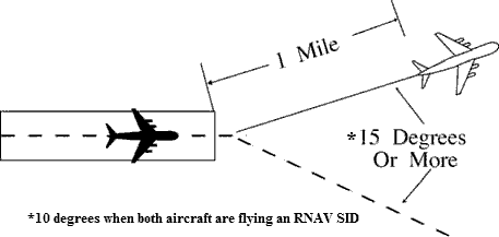
FIG 5-8-2 Simultaneous Departures 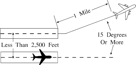
FIG 5-8-3 Simultaneous Departures 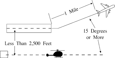
NOTE: This procedure does not apply when wake turbulence separation is required.
- Between simultaneous departures departing in the same direction from parallel runways/helicopter takeoff courses, authorize simultaneous takeoffs if the centerlines/takeoff courses are separated by at least 2,500 feet and courses diverge by 15 degrees or more immediately after departure. (See FIG 5-8-4, and FIG 5-8-5.)
- When both aircraft are flying an RNAV SID:
- Between successive departures from the same runway- 1 mile if courses diverge by 10 degrees or more
immediately after departure. (See FIG 5-8-1.)
NOTE: This procedure does not apply when wake turbulence separation is required.
- Between simultaneous departures from parallel runways/helicopter takeoff courses, authorize simultaneous takeoffs if the centerlines/takeoff courses are separated by at least 700 feet and less than 2,500 feet, courses diverge by 15 degrees or more, and departures are released in accordance with the release distance stagger stated in TBL 5-8-1 below.
-
Between simultaneous departures from parallel runways/helicopter takeoff courses, authorize simultaneous
takeoffs if the centerlines/takeoff courses are separated by at least 2,500 feet and courses diverge by 10
degrees or more immediately after departure. (See FIG 5-8-5, and FIG 5-8-6.)
NOTE: RNAV SIDs specific to this paragraph are those SIDs constructed with a specific lateral path that begins at the DER.
TBL 5-8-1 Departure Release Distances Distance to Divergence (Measured from the further DER) Minimum Centerline Separation Release Distance Stagger Immediately 700 1000 feet No later than 5 NM 1020 2000 feet No later than 8 NM 1130 3000 feet No later than 11 NM 1360 4000 feet NOTE: This procedure does not apply when wake turbulence separation is required.
FIG 5-8-4 Simultaneous Dependent Departures 
FIG 5-8-5 Parallel Runway Departures 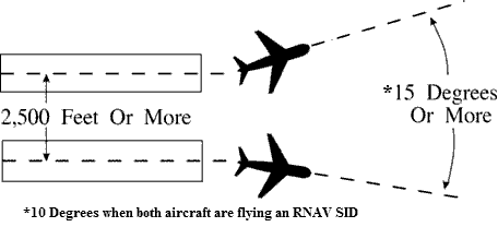
FIG 5-8-5 Parallel Helicopter Course Departures 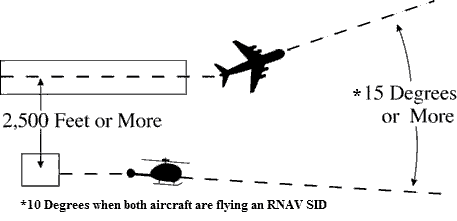
- Between successive departures from the same runway- 1 mile if courses diverge by 10 degrees or more
immediately after departure. (See FIG 5-8-1.)
- Between aircraft departing from diverging runways:
- Nonintersecting runways. Authorize simultaneous takeoffs if runways diverge by 15 degrees or more. (See FIG
5-8-7.)
FIG 5-8-7 Nonintersecting Runway Departures 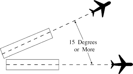
- Intersecting runways and/or helicopter takeoff courses which diverge by 15 degrees or more. Authorize
takeoff of a succeeding aircraft when the preceding aircraft has passed the point of runway and/or takeoff
course intersection. When applicable, apply the procedure in Paragraph 3-9-5, Anticipating Separation. (See
FIG 5-8-8 and FIG 5-8-9.)
FIG 5-8-8 Intersecting Runway Departures 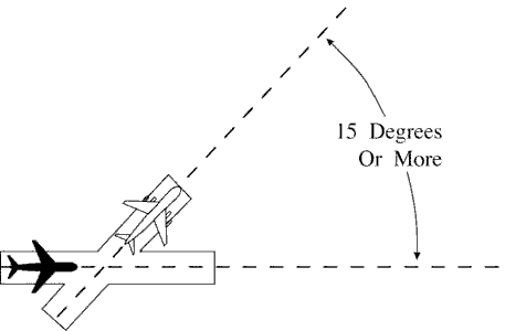
FIG 5-8-9 Intersecting Helicopter Course Departures 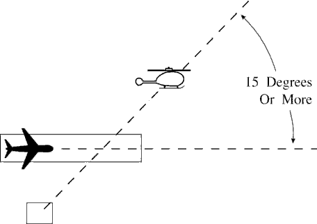
NOTE: This procedure does not apply when wake turbulence separation is required.
- Nonintersecting runways. Authorize simultaneous takeoffs if runways diverge by 15 degrees or more. (See FIG
5-8-7.)
5-8-4. DEPARTURE AND ARRIVAL
TERMINAL.Except as provided in para 5-8-5, Departures and Arrivals on Parallel or Nonintersecting Diverging Runways, separate a departing aircraft from an arriving aircraft on final approach by a minimum of 2 miles if separation will increase to a minimum of 3 miles (5 miles when 40 miles or more from the antenna) within 1 minute after takeoff.
- NOTE:
- 1. This procedure permits a departing aircraft to be released so long as an arriving aircraft is no closer than 2 miles from the runway at the time. This separation is determined at the time the departing aircraft commences takeoff roll.
- 2. Consider the effect surface conditions, such as ice, snow, and other precipitation, may have on known aircraft performance characteristics, and the influence these conditions may have on the pilot's ability to commence takeoff roll in a timely manner.
5-8-5. DEPARTURES AND ARRIVALS ON PARALLEL OR NONINTERSECTING DIVERGING RUNWAYS
TERMINAL. Authorize simultaneous operations between an aircraft departing on a runway and an aircraft on final approach to another parallel or nonintersecting diverging runway if the departure course diverges immediately by at least 30 degrees from the missed approach course until separation is applied and provided one of the following conditions is met:
NOTE: When one or both of the takeoff/landing surfaces is a helipad, consider the helicopter takeoff course as the runway centerline and the helipad center as the threshold.
- When parallel runway thresholds are even, the runway centerlines are at least 2,500 feet apart. (See FIG 5-8-10
and FIG 5-8-11.)
FIG 5-8-10 Parallel Thresholds are Even 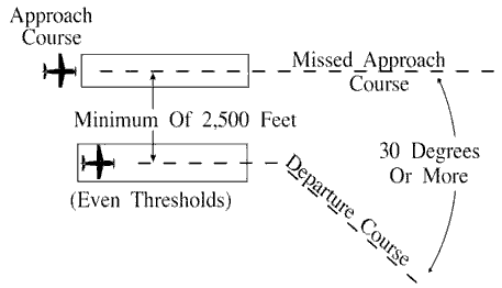
FIG 5-8-11 Parallel Thresholds are Even 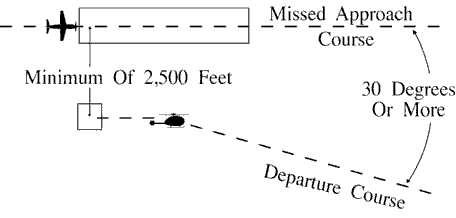
- When parallel runway thresholds are staggered and:
- The arriving aircraft is approaching the nearer runway: the centerlines are at least 1,000 feet apart and
the landing thresholds are staggered at least 500 feet for each 100 feet less than 2,500 the centerlines are
separated. (See FIG 5-8-12 and FIG 5-8-13.)
FIG 5-8-12 Parallel Thresholds are Staggered 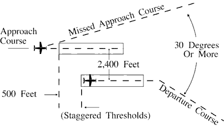
FIG 5-8-13 Parallel Thresholds are Staggered 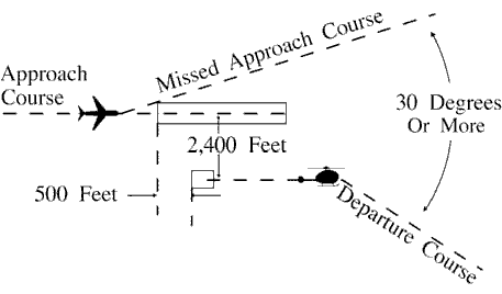
NOTE: In the event of a missed approach by an aircraft requiring wake turbulence separation behind it, apply the procedures in Paragraph 3-9-6, Same Runway Separation and/or Paragraph 3-9-8, Intersecting Runway/Intersecting Flight Path Operations to ensure that the larger aircraft does not overtake or cross in front of an aircraft departing from the adjacent parallel runway.
- The arriving aircraft is approaching the farther runway: the runway centerlines separation exceeds 2,500
feet by at least 100 feet for each 500 feet the landing thresholds are staggered. (See FIG 5-8-14.)
FIG 5-8-14 Parallel Thresholds are Staggered 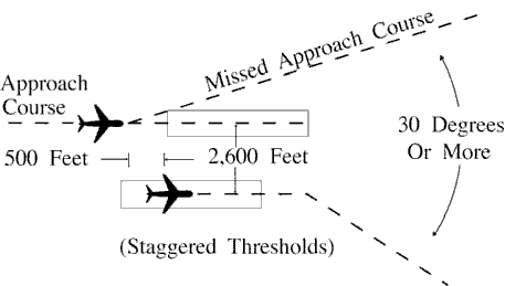
- The arriving aircraft is approaching the nearer runway: the centerlines are at least 1,000 feet apart and
the landing thresholds are staggered at least 500 feet for each 100 feet less than 2,500 the centerlines are
separated. (See FIG 5-8-12 and FIG 5-8-13.)
- When nonintersecting runways diverge by 15 degrees or more and runway edges do not touch. (See FIG 5-8-15.)
FIG 5-8-15 Diverging Nonintersecting Runways 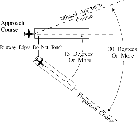
- When the aircraft on takeoff is a helicopter, hold the helicopter until visual separation is possible or apply the separation criteria in subparas a, b, or c.
Section 9. Radar Arrivals
5-9-1. VECTORS TO FINAL APPROACH COURSE
Except as provided in para 7-4-2, Vectors for Visual Approach, vector arriving aircraft to intercept the final approach course:
- At least 2 miles outside the approach gate unless one of the following exists:
- When the reported ceiling is at least 500 feet above the MVA/MIA and the visibility is at least 3 miles (report may be a PIREP if no weather is reported for the airport), aircraft may be vectored to intercept the final approach course closer than 2 miles outside the approach gate but no closer than the approach gate.
- If specifically requested by the pilot, aircraft may be vectored to intercept the final approach course inside the approach gate but no closer than the final approach fix.
EXCEPTION. Conditions 1 and 2 above do not apply to RNAV aircraft being vectored for a GPS or RNAV approach.
- Provide a minimum of 1,000 feet vertical separation between aircraft on opposite base legs unless another form of approved separation is established during turn-on to final approach.
- For a precision approach, at an altitude not above the glideslope/glidepath or below the minimum glideslope intercept altitude specified on the approach procedure chart.
- For a nonprecision approach, at an altitude which will allow descent in accordance with the published procedure.
NOTE: A pilot request for an “evaluation approach,” or a “coupled approach,” or use of a similar term, indicates the pilot desires the application of subparas a and b.
- EN ROUTE. The following provisions are required before an aircraft may be vectored to the final approach course:
- The approach gate and a line (solid or broken), depicting the final approach course starting at or passing through the approach gate and extending away from the airport, be displayed on the radar scope; for a precision approach, the line length must extend at least the maximum range of the localizer; for a nonprecision approach, the line length must extend at least 10NM outside the approach gate; and
- The maximum range selected on the radar display is 150 NM; or
- An adjacent radar display is set at 125 NM or less, configured for the approach in use, and is utilized for the vector to the final approach course.
- If unable to comply with subparas 1, 2, or 3 above, issue the clearance in accordance with Para 4-8-1, Approach Clearance.
5-9-2. FINAL APPROACH COURSE INTERCEPTION
- Assign headings that will permit final approach course interception on a track that does not exceed the interception angles specified in TBL 5-9-1.
TBL 5-9-1 Approach Course Interception Angle Distance from interception point to approach gate Maximum interception angle Less than 2 miles or triple simultaneous approaches in use 20 degrees 2 miles or more 30 degrees (45 degrees for helicopters) - If deviations from the final approach course are observed after initial course interception, apply the following:
- Outside the approach gate: apply procedures in accordance with subpara a, if necessary, vector the aircraft for another approach.
- Inside the approach gate: inform the pilot of the aircraft's position and ask intentions.
- PHRASEOLOGY
- (Ident) (distance) MILE(S) FROM THE AIRPORT, (distance) MILE(S) RIGHT/LEFT OF COURSE, SAY INTENTIONS.
NOTE: The intent is to provide for a track course intercept angle judged by the controller to be no greater than specified by this procedure.
- REFERENCE
- FAA Order JO 7110.65, Chapter 5, Section 9, Radar Arrivals, and Section 10, Radar Approaches- Terminal.
- EN ROUTE. When using a radar scope range above 125 NM, the controller must solicit and receive a pilot report that the aircraft is established on the final approach course. If the pilot has not reported established by the final approach gate, inform the pilot of his/her observed position and ask intentions.
NOTE: It may be difficult to accurately determine small distances when using very large range settings.
5-9-3. VECTORS ACROSS FINAL APPROACH COURSE
Inform the aircraft whenever a vector will take it across the final approach course and state the reason for such action.
NOTE: In the event you are unable to so inform the aircraft, the pilot is not expected to turn inbound on the final approach course unless approach clearance has been issued.
- PHRASEOLOGY
- EXPECT VECTORS ACROSS FINAL FOR (purpose).
- EXAMPLE
- “EXPECT VECTORS ACROSS FINAL FOR SPACING.”
5-9-4. ARRIVAL INSTRUCTIONS
Issue all of the following to an aircraft before it reaches the approach gate:
- Position relative to a fix on the final approach course. If none is portrayed on the radar display or if none is prescribed in the procedure, issue position information relative to the navigation aid which provides final approach guidance or relative to the airport.
- Vector to intercept the final approach course if required.
- Approach clearance except when conducting a radar approach. Issue approach clearance only after the aircraft is:
- Established on a segment of a published route or instrument approach procedure, or see FIG 5-9-1 Example 1.
FIG 5-9-1 Arrival Instructions 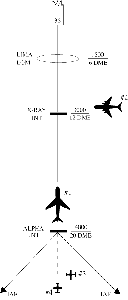
- EXAMPLE
- 1. Aircraft 1 was vectored to the final approach course but clearance was withheld. It is now at 4,000 feet and established on a segment of the instrument approach procedure. “Seven miles from X-RAY. Cleared I-L-S runway three six approach.” (See FIG 5-9-1.)
- 2. Aircraft 2 is being vectored to a published segment of the final approach course, 4 miles from LIMA at 2,000 feet. The MVA for this area is 2,000 feet. “Four miles from LIMA. Turn right heading three four zero. Maintain two thousand until established on the localizer. Cleared I-L-S runway three six approach.” (See FIG 5-9-1.)
- 3. Aircraft 3 is being vectored to intercept the final approach course beyond the approach segments, 5 miles from Alpha at 5,000 feet. the MVA for this area is 4,000 feet. “Five miles from Alpha. Turn right heading three three zero. Cross Alpha at or above four thousand. Cleared I-L-S runway three six approach.” (See FIG 5-9-1.)
- 4. Aircraft 4 is established on the final approach course beyond the approach segments, 8 miles from Alpha at 6,000 feet. The MVA for this area is 4,000 feet. “Eight miles from Alpha. Cross Alpha at or above four thousand. Cleared I-L-S runway three six approach.” (See FIG 5-9-1.)
- Assigned an altitude to maintain until the aircraft is established on a segment of a published route or instrument approach procedure.
FIG 5-9-2 Arrival Instructions 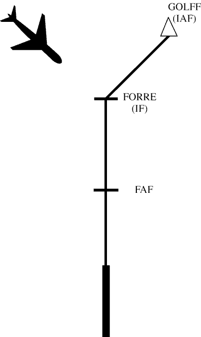
- EXAMPLE
- The aircraft is being vectored to the intermediate fix FORRE for an RNAV approach. “Seven miles from FORRE, cleared direct FORRE, cross FORRE at or above four thousand, cleared RNAV runway one eight approach.”
- NOTE:
- 1. The altitude assigned must assure IFR obstruction clearance from the point at which the approach clearance is issued until established on a segment of a published route or instrument approach procedure.
- 2. If the altitude assignment is VFR-on-top, it is conceivable that the pilot may elect to remain high until arrival over the final approach fix which may require the pilot to circle to descend so as to cross the final approach fix at an altitude that would permit landing.
- 3. Aircraft being vectored to the intermediate fix in FIG 5-9-2 must meet all the provisions described in subpara 4-8-1h2.
- Established on a segment of a published route or instrument approach procedure, or see FIG 5-9-1 Example 1.
- Instructions to do one of the following:
NOTE: The principal purpose of this paragraph is to ensure that frequency changes are made prior to passing the final approach fix. However, at times it will be desirable to retain an aircraft on the approach control frequency to provide a single-frequency approach or other radar services. When this occurs, it will be necessary to relay tower clearances or instructions to preclude changing frequencies prior to landing or approach termination.
- Monitor local control frequency, reporting to the tower when over the approach fix.
- Contact the tower on local control frequency.
- Contact the final controller on the appropriate frequency if radar service will be provided on final on a different frequency.
- When radar is used to establish the final approach fix, inform the pilot that after being advised that he/she is over the fix he/she is to contact the tower on local control frequency.
- EXAMPLE
- “Three miles from final approach fix. Turn left heading zero one zero. Maintain two thousand until established on the localizer. Cleared I-L-S runway three six approach. I will advise when over the fix.”
- “Over final approach fix. Contact tower one one eight point one.”
NOTE: ARSR may be used for establishment of initial approach and intermediate approach fixes only. ASR must be used to establish the final approach fix.
- Where a Terminal Arrival Area (TAA) has been established to support RNAV approaches, inform the aircraft of its position relative to the appropriate IAF and issue the approach clearance. (See FIG 5-9-3.)
- EXAMPLE
- 1. Aircraft 1: The aircraft is in the straight in area of the TAA. “Seven miles from CENTR, Cleared R-NAV Runway One Eight Approach.”
- 2. Aircraft 2: The aircraft is in the left base area of the TAA. “One five miles from LEFTT, Cleared R-NAV Runway One Eight Approach.”
- 3. Aircraft 3: The aircraft is in the right base area of the TAA. “Four miles from RIGHT, Cleared R-NAV Runway One Eight Approach.”
FIG 5-9-3 Basic “T” Design 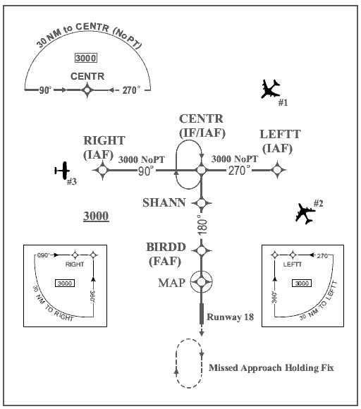
5-9-5. APPROACH SEPARATION RESPONSIBILITY
interpretation 14- The radar controller performing the approach control function is responsible for separation of radar arrivals unless visual separation is provided by the tower, or a letter of agreement/facility directive authorizes otherwise. Radar final controllers ensure that established separation is maintained between aircraft under their control and other aircraft established on the same final approach course.
NOTE: The radar controller may be a controller in an ARTCC, a terminal facility, or a tower controller when authorized to perform the approach control function in a terminal area.
- REFERENCE
- FAA Order JO 7110.65, Para 2-1-19, Wake Turbulence.
- FAA Order JO 7110.65, Para 5-5-1, Application.
- FAA Order JO 7110.65, Para 7-2-1, Visual Separation.
- FAA Order JO 7110.65, Para 5-5-4, Minima.
- FAA Order JO 7210.3, Para 2-1-16, Authorization for Separation Services by Towers.
- When timed approaches are being conducted, the radar controller must maintain the radar separation specified in Para 6-7-5, Interval Minima, until the aircraft is observed to have passed the final approach fix inbound (nonprecision approaches) or the OM or the fix used in lieu of the outer marker (precision approaches) and is within 5 miles of the runway on the final approach course or until visual separation can be provided by the tower.
5-9-6. SIMULTANEOUS DEPENDENT APPROACHES
TERMINAL
-
Apply the following minimum separation when conducting simultaneous dependent approaches:
- Provide a minimum of 1,000 feet vertical or a minimum of 3 miles radar separation between aircraft during turn on.
-
Provide a minimum of 1 mile radar separation diagonally between successive aircraft on adjacent final approach
courses when runway centerlines are at least 2,500 feet but no more than 3,600 feet apart.
FIG 5-9-4 Simultaneous Dependent Approaches 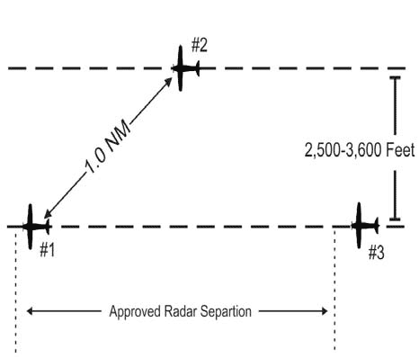
- EXAMPLE
- In FIG 5-9-4, Aircraft 2 is 1.0 mile from Aircraft 1. Approved radar separation must be maintained between Aircraft 1 and Aircraft 3.
-
Provide a minimum of 1.5 miles radar separation diagonally between successive aircraft on adjacent final
approach courses when runway centerlines are more than 3,600 feet but no more than 8,300 feet apart.
FIG 5-9-5 Simultaneous Dependent Approaches 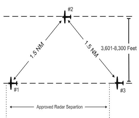
- EXAMPLE
- In FIG 5-9-5, Aircraft 2 is 1.5 miles from Aircraft 1, and Aircraft 3 is 1.5 miles or more from Aircraft 2. Approved radar separation must be maintained between aircraft on the same final.
-
Provide a minimum of 2 miles radar separation diagonally between successive aircraft on adjacent final
approach courses where runway centerlines are more than 8,300 feet but no more than 9,000 feet apart.
FIG 5-9-6 Simultaneous Dependent Approaches 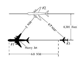
- EXAMPLE
- In FIG 5-9-6, Aircraft 2 is 2 miles from heavy Aircraft 1. Aircraft 3 is a small aircraft and is 6 miles from Aircraft 1. *The resultant separation between Aircraft 2 and 3 is at least 4.7 miles.
-
Provide the minimum approved radar separation between aircraft on the same final approach course.
- REFERENCE
- FAA Order JO 7110.65, Section 5, Radar Separation, Para 5-5-4, Minima.
-
The following conditions are required when applying the minimum radar separation on adjacent final approach
courses allowed in subparagraph a:
- NOTE:
- 1. Established on RNP (EoR) operations are not authorized in conjunction with simultaneous dependent approaches.
- 2. Simultaneous dependent approaches may only be conducted where instrument approach charts specifically authorize simultaneous approaches.
- Apply this separation standard only after aircraft are established on the parallel final approach course.
- Straight-in landings will be made.
- Missed approach procedures do not conflict.
- Aircraft are informed that approaches to both runways are in use. This information may be provided through the ATIS.
-
Approach control must have the interphone capability of communicating directly with the local controller at
locations where separation responsibility has not been delegated to the tower.
NOTE: The interphone capability is an integral part of this procedure when approach control has the sole separation responsibility.
- REFERENCE
- FAA Order JO 7110.65, Para 5-9-5, Approach Separation Responsibility.
- FAA Order JO 7210.3, Para 2-1-16, Authorization for Separation Services by Towers.
- Consideration should be given to known factors that may in any way affect the safety of the instrument approach phase of flight, such as surface wind direction and velocity, wind shear alerts/reports, severe weather activity, etc. Closely monitor weather activity that could impact the final approach course. Weather conditions in the vicinity of the final approach course may dictate a change of approach in use.
5-9-7. SIMULTANEOUS INDEPENDENT APPROACHES - DUAL & TRIPLE
TERMINAL
-
Apply the following minimum separation when conducting simultaneous independent approaches:
-
Provide a minimum of 1,000 feet vertical or a minimum of 3 miles radar separation between aircraft:
- (a) during turn-on to parallel final approach,
- or,
- (b) until aircraft are established on a published segment of an approach authorized for Established on RNP (EoR) operations.
NOTE: Aircraft are considered EoR on an initial or intermediate segment of an instrument approach authorized for EoR operations after the approach clearance has been issued, read back by the pilot and the aircraft is observed on the published procedure (lateral and vertical path, and within any procedure specified speed restriction), and is conducting a simultaneous independent parallel approach with an authorized simultaneous instrument approach to a parallel runway.
- Dual parallel runway centerlines are at least 3,600 feet apart, or dual parallel runway centerlines are at least 3,000 feet apart with a 2.5° to 3.0° offset approach to either runway.
-
Triple parallel approaches may be conducted when:
- (a) Parallel runway centerlines are at least 3,900 feet apart; or
- (b) Parallel runway centerlines are at least 3,000 feet apart, a 2.5° to 3.0° offset approach to both outside runways; or
- (c) Parallel runway centerlines are at least 3,000 feet apart, a single 2.5° to 3.0° offset approach to either outside runway while parallel approaches to the remaining two runways are separated by at least 3,900 feet.
- (d) Parallel approaches to airports where the airport field elevation is more than 2,000 feet MSL require the use of the final monitor aid (FMA) system.
-
Provide the minimum applicable radar separation between aircraft on the same final approach course.
Except when conducting an EoR operation, no two aircraft will be assigned the same altitude during turn-on to final. All three aircraft will be assigned altitudes which differ by a minimum of 1,000 feet. Example: 3,000, 4,000, 5,000; 7,000, 8,000, 9,000.
-
Provide a minimum of 1,000 feet vertical or a minimum of 3 miles radar separation between aircraft:
-
At locations with high update rate surveillance, simultaneous independent approaches may be conducted where the
surveillance update rate is 1 second or faster, the system processing time is 3 seconds or faster, and under the
following conditions:
- Dual parallel runway centerlines are at least 3,200 feet apart, or dual parallel runway centerlines are at least 2,500 feet apart with a 2.5° to 3.0° offset approach to either runway.
-
Triple parallel runway centerlines are at least 3,400 feet apart, or triple parallel runway centerlines are at
least 2,500 feet apart with a 2.5° to 3.0° offset approach to both outside runways, or triple parallel
runway centerlines are at least 2,500 feet apart, a single 2.5° to 3.0° offset approach to either
outside runway while parallel approaches to the remaining two runways are separated by at least 3,400 feet.
NOTE: Aircraft without functioning ADS-B Out are restricted from utilizing these high update rate (HUR) procedures unless an alternative HUR surveillance source providing one-second or faster target report updating is utilized.
-
A surveillance update rate of at least 1 second is required for monitoring the no transgression zone (NTZ)
when conducting simultaneous independent approaches to the runway centerline spacing (RCLS) provided in this
paragraph.
- NOTE:
- 1. HUR procedures cannot be conducted if notified that a one second update rate is not being provided.
- 2. Where RCLS is ≤3400 feet, the normal operating zone (NOZ) is constant at 700 feet; and for RCLS ≥3400 feet, the no transgression zone (NTZ) remains constant at 2000 feet.
- Provide the minimum applicable radar separation between aircraft on the same final approach course.
-
A color digital display set to a 4 to 1 (4:1) aspect ratio (AR) with visual and aural alerts, such as the STARS
final monitor aid (FMA), and a surveillance update rate at 4.8 seconds or faster must be used to monitor
approaches where:
- Dual parallel runway centerlines are at least 3,000 and less than 4,300 feet apart.
- Triple parallel runway centerlines are at least 3,000 but less than 5,000 feet apart.
-
Triple parallel approaches to airports where the airport field elevation is more than 2,000 feet MSL require
use of the FMA system.
NOTE: At locations where the airfield elevation is 2000 feet or less, FMA is not required to monitor the NTZ for runway centerlines 4,300 feet or greater for dual runways, and 5,000 feet or greater for triple operations.
-
The following conditions must be met when conducting dual or triple simultaneous independent approaches:
NOTE: Simultaneous independent approaches may only be conducted where instrument approach charts specifically authorize simultaneous approaches.
- REFERENCE
- FAA Order JO 7210.3, Para 10-4-6, Simultaneous Approaches (Dependent/Independent).
- Straight-in landings will be made.
- All appropriate communication, navigation, and surveillance systems are operating normally.
- Inform aircraft that simultaneous independent approaches are in use, or when runway centerlines are less than 4,300 feet, PRM approaches are in use, prior to aircraft departing an outer fix. This information may be provided through the ATIS.
-
Clear the aircraft to descend to the appropriate glideslope/glidepath intercept altitude soon enough to
provide a period of level flight to dissipate excess speed. Provide at least 1 mile of straight flight prior
to the final approach course intercept.
NOTE: Not applicable to approaches with RF legs.
-
An NTZ is established an equal distance between extended runway final approach courses and must be depicted on
the monitor display. The primary responsibility for navigation on the final approach course rests with the
pilot. Control instructions and information are issued only to ensure separation between aircraft and to
prevent aircraft from penetrating the NTZ.
NOTE: Where RCLS is ≤3400 feet, the normal operating zone (NOZ) is constant at 700 feet; and for RCLS ≥3400 feet, the no transgression zone (NTZ) remains constant at 2000 feet.
-
Monitor all approaches regardless of weather. Monitor local control frequency to receive any aircraft
transmission. Issue control instructions as necessary to ensure aircraft do not enter the NTZ.
- NOTE:
- 1. Separate monitor controllers, each with transmit/receive and override capability on the local control frequency, must ensure aircraft do not penetrate the depicted NTZ. For PRM approaches, a transmit-only secondary “PRM frequency” is also used. Facility directives must define responsibility for providing the minimum applicable longitudinal separation between aircraft on the same final approach course.
- 2. The aircraft is considered the center of the primary radar return for that aircraft, or, if an FMA or other color final monitor aid is used, the center of the digitized target of that aircraft, for the purposes of ensuring an aircraft does not penetrate the NTZ. The provisions of para 5-5-2, Target Separation, apply also.
- Communications transfer to the tower controller's frequency must be completed prior to losing 1,000 feet vertical or 3 miles radar separation between aircraft.
-
The following procedures must be used by the final monitor controllers:
-
For PRM approaches, provide position information to an aircraft that is left/right of the depicted final
approach course centerline, and in your judgment is continuing on a track that may penetrate the NTZ.
- PHRASEOLOGY
- (Aircraft call sign) I SHOW YOU (left/right) OF THE FINAL APPROACH COURSE.
-
Instruct the aircraft to return to the correct final approach course when aircraft are observed to overshoot
the turn-on or to continue on a track which will penetrate the NTZ.
- PHRASEOLOGY
- YOU HAVE CROSSED THE FINAL APPROACH COURSE. TURN (left/right) IMMEDIATELY AND RETURN TO THE FINAL APPROACH COURSE,
- or
- TURN (left/right) AND RETURN TO THE FINAL APPROACH COURSE.
-
Instruct aircraft on the adjacent final approach course to alter course to avoid the deviating aircraft when
an aircraft is observed penetrating or in your judgment will penetrate the NTZ.
NOTE: For PRM approaches, an instruction that may include a descent to avoid the deviating aircraft should only be used when there is no other reasonable option available to the controller. In such a case, the descent must not put the aircraft below the MVA.
- PHRASEOLOGY
- TRAFFIC ALERT, (call sign), TURN (right/left) IMMEDIATELY HEADING (degrees), CLIMB AND MAINTAIN (altitude).
-
Terminate radar monitoring when one of the following occurs:
- (a) Visual separation is applied.
- (b) The aircraft reports the approach lights or runway in sight.
- (c) The aircraft is 1 mile or less from the runway threshold, if procedurally required and contained in facility directives.
- Do not inform the aircraft when radar monitoring is terminated.
-
For PRM approaches, provide position information to an aircraft that is left/right of the depicted final
approach course centerline, and in your judgment is continuing on a track that may penetrate the NTZ.
- Consideration should be given to known factors that may in any way affect the safety of the instrument approach phase of flight when simultaneous independent approaches, or PRM approaches, if applicable, are being conducted to parallel runways. Factors include, but are not limited to, wind direction/velocity, windshear alerts/reports, severe weather activity, etc. Closely monitor weather activity that could impact the final approach course. Weather conditions in the vicinity of the final approach course may dictate a change of approach in use.
5-9-8. SIMULTANEOUS INDEPENDENT CLOSE PARALLEL APPROACHES - PRECISION RUNWAY MONITOR (PRM) APPROACHES
TERMINAL
When conducting PRM approaches, apply all pertinent provisions of paragraph 5-9-7 and the following:
- PRM approaches may only be conducted when charted in the approach title, and where instrument approach charts specifically authorize simultaneous approaches.
- PRM approaches must be assigned when conducting instrument approaches to dual and triple parallel runways with runway centerlines separated by less than 4,300 feet.
5-9-9. SIMULTANEOUS OFFSET INSTRUMENT APPROACHES (SOIA)
TERMINAL
-
Simultaneous offset instrument approaches (SOIA) may be conducted at FAA designated airports that have an
authorization issued by the Director, Operations-Headquarters, AJT-2, in coordination with AFS with parallel
runways that have centerlines separated by at least 750 feet and less than 3,000 feet with one final approach
course offset by 2.5 to 3.0 degrees; and
-
Provide a minimum of 1,000 feet vertical or a minimum of 3 miles radar separation between aircraft during
turn-on to final approaches.
NOTE: Communications transfer to the tower controller's frequency must be completed prior to losing vertical separation between aircraft.
- Provide the minimum applicable radar separation between aircraft on the same final approach course.
- Provide the minimum applicable radar separation between the trailing offset aircraft of a leading SOIA pair and the lead straight-in aircraft in the subsequent SOIA pair when the parallel runways have centerlines separated by less than 2,500 feet.
-
Provide a minimum of 1,000 feet vertical or a minimum of 3 miles radar separation between aircraft during
turn-on to final approaches.
-
The following conditions are required when applying the minimum separation between lead straight-in and offset
trailing approaches with glideslope courses or vertical navigation authorized in subparagraph a above:
- Straight-in landings will be made.
- All appropriate communication, navigation, and surveillance systems are operating normally.
- Inform aircraft that PRM approaches are in use prior to aircraft departing an outer fix. This information may be provided through the ATIS.
-
Clear the aircraft to descend to the appropriate glideslope/glidepath intercept altitude soon enough to
provide a period of level flight to dissipate excess speed. Provide at least 1 mile of straight flight prior
to the final approach course intercept.
NOTE: Not applicable to approaches with RF legs.
-
A no transgression Zone (NTZ) is established an equal distance between extended runway final approach courses
and must be depicted on the monitor display. The NTZ begins prior to the point where adjacent inbound aircraft
first lose vertical separation and extends to a point coincident with the location of the offset approach MAP.
The primary responsibility for navigation on the final approach course rests with the pilot. Control
instructions and information are issued only to ensure separation between aircraft and to prevent aircraft
from penetrating the NTZ.
Where RCLS is ≤3400 feet, the normal operating zone (NOZ) is constant at 700 feet; and for RCLS ≥3400 feet, the no transgression zone (NTZ) remains constant at 2000 feet.
- Monitor all approaches regardless of weather. Monitor local control frequency to receive any aircraft transmission. Issue control instructions as necessary to ensure aircraft do not enter the NTZ.
-
Separate monitor controllers, each with transmit/receive and override capability on the local control
frequency, must ensure aircraft do not penetrate the depicted NTZ. Facility directives must define the
responsibility for providing the minimum applicable longitudinal separation between aircraft on the same final
approach course and the minimum applicable longitudinal separation between the trailing offset aircraft of a
leading SOIA pair and the lead straight in aircraft in the subsequent SOIA pair when the parallel runways have
centerlines separated by less than 2,500 feet.
NOTE: The aircraft is considered the center of the digitized target for that aircraft for the purposes of ensuring an aircraft does not penetrate the NTZ.
-
The following procedures must be used by the final monitor controllers:
-
Provide position information to an aircraft that is (left/right) of the depicted final approach course
centerline, and in your judgment is continuing on a track that may penetrate the NTZ.
- PHRASEOLOGY
- (Aircraft call sign) I SHOW YOU (left/right) OF THE FINAL APPROACH COURSE.
-
Instruct the aircraft to return immediately to the correct final approach course when aircraft are observed to
overshoot the turn-on or continue on a track which will penetrate the NTZ.
- PHRASEOLOGY
- YOU HAVE CROSSED THE FINAL APPROACH COURSE. TURN (left/right) IMMEDIATELY AND RETURN TO FINAL APPROACH COURSE.
- or
- TURN (left/right) AND RETURN TO THE FINAL APPROACH COURSE.
-
Instruct aircraft on the adjacent final approach course to alter course to avoid the deviating aircraft when
an aircraft is observed penetrating or in your judgment will penetrate the NTZ.
NOTE: An instruction that may include a descent to avoid the deviating aircraft should only be used when there is no other reasonable option available to the controller. In such a case, the descent must not put the aircraft below the MVA.
- PHRASEOLOGY
- TRAFFIC ALERT, (call sign), TURN (left/right) IMMEDIATELY HEADING (DEGREES), CLIMB AND MAINTAIN (altitude).
-
Terminate radar monitoring when one of the following occurs:
- (a) The lead straight in aircraft passes the end of the NTZ nearest the runway threshold.
- (b) The trailing offset aircraft passes the end of the NTZ nearest the runway threshold and has reported the lead straight in aircraft in sight.
- (c) The aircraft begins the visual segment of the approach.
- Do not inform the aircraft when radar monitoring is terminated.
-
Provide position information to an aircraft that is (left/right) of the depicted final approach course
centerline, and in your judgment is continuing on a track that may penetrate the NTZ.
-
Advise the pilot of the trailing offset aircraft of traffic on the adjacent lead straight-in approach course, if
that traffic will be a factor in the visual segment of the approach. The provisions of Paragraph 7-2-1, Visual
Separation, subparagraph a1, concerning visual separation between aircraft being provided by the tower must not be
applied to aircraft conducting SOIAs.
NOTE: Once advised, the pilot is authorized to continue past the offset approach MAP if all of the following conditions are met: The pilot has the straight-in approach traffic in sight and expects the traffic to remain in sight; the pilot advises ATC that the traffic is in sight; and the pilot has the runway environment in sight. Otherwise, it is the pilot's responsibility to execute a missed approach at the offset approach MAP.
-
Ensure that the trailing offset aircraft is positioned to facilitate the flight crew's ability to see the lead
straight in traffic from the nominal clear-of-clouds point to the offset approach MAP so that the flight crew can
remain separated from that traffic visually from the offset approach MAP to the runway threshold.
NOTE: After accepting a clearance for an offset PRM approach, pilots must remain on the offset approach course until passing the offset approach MAP prior to alignment with the runway centerline. Between the offset approach MAP and the runway threshold, the pilot of the offset approach aircraft assumes visual separation responsibility from the aircraft on the straight-in approach, which means maneuvering the aircraft as necessary to avoid the straight in approach traffic until landing, and providing wake turbulence avoidance, if necessary.
- In the visual segment between the offset approach MAP and the runway threshold, if the pilot of the trailing offset aircraft loses visual contact with the lead straight-in traffic, the pilot must advise ATC as soon as practical and follow the published missed approach procedure. If necessary, issue alternate missed approach instructions.
-
Wake turbulence requirements between aircraft on adjacent final approach courses inside the offset approach MAP
are as follows (standard in-trail wake separation must be applied between aircraft on the same approach course):
- When runways are at least 2,500 feet apart, there are no wake turbulence requirements between aircraft on adjacent final approach courses.
- For runways less than 2,500 feet apart, whenever the ceiling is greater than or equal to 500 feet above the MVA, wake vortex spacing between aircraft on adjacent final approach courses need not be applied.
- For runways less than 2,500 feet apart, whenever the ceiling is less than 500 feet above the MVA, wake vortex spacing between aircraft on adjacent final approach courses, as described in Para 5-5-4, Minima, must be applied unless acceptable mitigating techniques and operational procedures have been documented and verified by an AFS safety assessment and authorized by the Director, Operations-Headquarters, AJT-2. The wake turbulence mitigation techniques employed will be based on each airport's specific runway geometry and meteorological conditions and implemented through local facility directives.
- Issue all applicable wake turbulence advisories.
- REFERENCE
- FAA Order JO 8260.49, Para 13.0, Wake Turbulence Requirements.
- FAA Order JO 7210.3, Para 10-4-6, Simultaneous Independent Approaches.
- FAA Order JO 7110.65, Para 2-1-20, Wake Turbulence Cautionary Advisories.
- FAA Order JO 7110.65, Para 5-5-4, Minima.
- Consideration should be given to known factors that may in any way affect the safety of the instrument approach phase of flight when conducting SOIA to parallel runways. Factors include but are not limited to wind direction/velocity, wind-shear alerts/reports, severe weather activity, etc. Closely monitor weather activity that could impact the final approach course. Weather conditions in the vicinity of the final approach course may dictate a change of the approach in use.
5-9-10. SIMULTANEOUS INDEPENDENT APPROACHES TO WIDELY - SPACED PARALLEL RUNWAYS WITHOUT FINAL MONITORS
TERMINAL
- Simultaneous independent approaches to widely-spaced parallel runways may only be conducted where instrument approach charts specifically authorize simultaneous approaches.
-
Apply the following minimum separation when conducting simultaneous independent approaches to runway centerlines
that are separated by more than 9,000 feet with a field elevation at or below 5,000 feet MSL, or 9,200 feet
between runway centerlines with a field elevation above 5,000 feet MSL:
-
Provide a minimum of 1,000 feet vertical or a minimum of 3 miles radar separation between aircraft:
- (a) during turn-on to parallel final approach,
- or,
-
(b) conducting EoR operations, until aircraft are established on a published segment of an approach
authorized for EoR operations.
NOTE: Aircraft are considered EoR on an initial or intermediate segment of an instrument approach authorized for EoR operations after the approach clearance has been issued, read back by the pilot and the aircraft is observed on the published procedure (lateral and vertical path, and within any procedure specified speed restriction), and is conducting a simultaneous independent parallel approach with an authorized simultaneous instrument approach to a parallel runway.
- REFERENCE
- FAA Order JO 7210.3, Paragraph 10-4-7, Simultaneous Widely-Spaced Parallel Operations
- P/CG Term - Required Navigation Performance (RNP)
- P/CG Term - Established on RNP Concept
- Provide the minimum applicable radar separation between aircraft on the same final approach course.
-
Provide a minimum of 1,000 feet vertical or a minimum of 3 miles radar separation between aircraft:
-
The following conditions are required when applying the minimum separation on widely-spaced parallel courses
allowed in subparagraph b:
- Straight-in landings will be made.
- The approach system, radar, and appropriate frequencies are operating normally.
- Inform aircraft that simultaneous approaches are in use prior to aircraft departing an outer fix. This information may be provided through the ATIS.
-
Clear an aircraft to descend to the appropriate glideslope/glidepath intercept altitude soon enough to provide
a period of level flight to dissipate excess speed. Provide at least 1 mile of straight flight prior to the
final approach course intercept.
NOTE: Not applicable to approaches with RF legs.
- Separate final and local controllers are required for each final. Aircraft on the final must be on the appropriate final controller frequency for that runway.
- Transfer of communication to the tower controller's frequency must be specified in a facility directive and/or Letter of Agreement.
-
The following procedures must be used by the final approach controllers:
NOTE: There is no requirement for establishment of a NTZ.
-
Instruct the aircraft to return to the correct final approach course when that aircraft is observed to
overshoot the turn-on or continue on a track which deviates from the final approach course in the direction of
the adjacent approach course.
- PHRASEOLOGY
- YOU HAVE CROSSED THE FINAL APPROACH COURSE. TURN (left/right) IMMEDIATELY AND RETURN TO THE FINAL APPROACH COURSE,
- or
- TURN (left/right) AND RETURN TO THE FINAL APPROACH COURSE.
-
Instruct aircraft on adjacent final approach course to alter course to avoid the deviating aircraft when an
aircraft is observed, or in the controller's judgment, has deviated from the final approach course in the
direction of the adjacent approach course.
- PHRASEOLOGY
- TRAFFIC ALERT, (call sign), TURN (left/right) IMMEDIATELY HEADING (degrees), CLIMB AND MAINTAIN (altitude)
-
Instruct the aircraft to return to the correct final approach course when that aircraft is observed to
overshoot the turn-on or continue on a track which deviates from the final approach course in the direction of
the adjacent approach course.
- Consideration should be given to known factors that may in any way affect the safety of the instrument approach phase of flight when simultaneous approaches are being conducted to parallel runways. Factors include, but are not limited to, wind direction/velocity, wind-shear alerts/reports, severe weather activity, etc. Closely monitor weather activity that could impact the final approach course. Weather conditions in the vicinity of the final approach course may dictate a change of approach in use.
5-9-11. TRANSITIONAL PROCEDURE
When aircraft are conducting simultaneous dependent, independent, or any approaches allowing for reduced separation, and one of the aircraft executes a go-around or has its approach clearance terminated and prior to losing the approved reduced separation, control instructions must be expeditiously issued to increase separation between the applicable aircraft. These control instructions must establish approved separation (for example, altitude and/or lateral separation via divergence). In addition, wake turbulence cautionary advisories must be issued in accordance with FAA Order JO 7110.65, Paragraph 2-1-20, Wake Turbulence Cautionary Advisories.
Section 10. Radar Approaches - Terminal
5-10-1. APPLICATION
- Provide radar approaches in accordance with standard or special instrument approach procedures.
- A radar approach may be given to any aircraft upon request and may be offered to aircraft in distress regardless of weather conditions or to expedite traffic.
NOTE: Acceptance of a radar approach by a pilot does not waive the prescribed weather minima for the airport or for the particular aircraft operator concerned. The pilot is responsible for determining if the approach and landing are authorized under the existing weather minima.
5-10-2. APPROACH INFORMATION
- Issue the following information to an aircraft that will conduct a radar approach. Current approach information contained in the ATIS broadcast may be omitted if the pilot states the appropriate ATIS broadcast code. All items listed below, except for subparagraph 3 may be omitted after the first approach if repeated approaches are made and no change has occurred. Transmissions with aircraft in this phase of the approach should occur approximately every minute.
- Altimeter setting.
- If available, ceiling and visibility if the ceiling at the airport of intended landing is reported below 1,000 feet or below the highest circling minimum, whichever is greater, or if the visibility is less than 3 miles. Advise pilots when weather information is available via the Automated Weather Observing System (AWOS)/Automated Surface Observing System (ASOS) and, if requested, issue the appropriate frequency.
NOTE: Automated weather observing systems may be set to provide one minute updates. This one minute data may be useful to the pilot for possible weather trends. Controllers provide service based solely on official weather, i.e., hourly and special observations.
- Issue any known changes classified as special weather observations as soon as possible. Special weather observations need not be issued after they are included in the ATIS broadcast and the pilot states the appropriate ATIS broadcast code.
- Pertinent information on known airport conditions if they are considered necessary to the safe operation of the aircraft concerned.
- Lost communication procedures as specified in para 5-10-4, Lost Communications.
- Before starting final approach:
- NOTE:
- 1. ASR approach procedures may be prescribed for specific runways, for an airport/heliport, and for helicopters only to a “point-in-space,“ i.e., a MAP from which a helicopter must be able to proceed to the landing area by visual reference to a prescribed surface route.
- 2. Occasionally, helicopter PAR approaches are available to runways where conventional PAR approaches have been established. In those instances where the two PAR approaches serve the same runway, the helicopter approach will have a steeper glide slope and a lower decision height. By the controllers designating the approach to be flown, the helicopter pilot understands which of the two approaches he/she has been vectored for and which set of minima apply.
- Inform the aircraft of the type of approach, runway, airport, heliport, or other point, as appropriate, to which the approach will be made. Specify the airport name when the approach is to a secondary airport.
- PHRASEOLOGY
- THIS WILL BE A P-A-R/SURVEILLANCE APPROACH TO:
- RUNWAY (runway number),
- or
- (airport name) AIRPORT, RUNWAY (runway number),
- or
- (airport name) AIRPORT/HELIPORT.
- THIS WILL BE A COPTER P-A-R APPROACH TO:
- RUNWAY (runway number),
- or
- (airport name) AIRPORT, RUNWAY (runway number),
- or
- (airport name) AIRPORT/HELIPORT.
- For surveillance approaches, specify the location of the MAP in relation to the runway/airport/heliport.
- PHRASEOLOGY
- MISSED APPROACH POINT IS (distance) MILE(S) FROM RUNWAY/AIRPORT/HELIPORT,
- or for a point-in-space approach,
- A MISSED APPROACH POINT (distance) MILE(S) (direction from landing area) OF (airport name) AIRPORT/HELIPORT.
- EXAMPLE
- Helicopter point-in-space approach:
- “Army copter Zulu Two, this will be a surveillance approach to a missed approach point, three point five miles south of Creedon Heliport.”
- Inform an aircraft making an approach to an airport not served by a tower that no traffic or landing runway information is available for that airport.
- PHRASEOLOGY
- NO TRAFFIC OR LANDING RUNWAY INFORMATION AVAILABLE FOR THE AIRPORT.
5-10-3. NO-GYRO APPROACH
When an aircraft will make a no-gyro surveillance or a PAR approach:
- Before issuing a vector, inform the aircraft of the type of approach.
- PHRASEOLOGY
- THIS WILL BE A NO-GYRO SURVEILLANCE/P-A-R APPROACH.
- Instruct the aircraft when to start and stop turn.
- PHRASEOLOGY
- TURN LEFT/RIGHT.
- STOP TURN.
- After turn on to final approach has been made and prior to the aircraft reaching the approach gate, instruct the aircraft to make half-standard rate turns.
- PHRASEOLOGY
- MAKE HALF-STANDARD RATE TURNS.
5-10-4. LOST COMMUNICATIONS
When weather reports indicate that an aircraft will likely encounter IFR weather conditions during the approach, take the following action as soon as possible after establishing radar identification and radio communications (may be omitted after the first approach when successive approaches are made and the instructions remain the same):
NOTE: Air traffic control facilities at U.S. Army and U.S. Air Force installations are not required to transmit lost communications instructions to military aircraft. All military facilities will issue specific lost communications instructions to civil aircraft when required.
- If lost communications instructions will require the aircraft to fly on an unpublished route, issue an appropriate altitude to the pilot. If the lost communications instructions are the same for both pattern and final, the pattern/vector controller must issue both. Advise the pilot that if radio communications are lost for a specified time interval (not more than 1 minute) on vector to final approach, 15 seconds on a surveillance final approach, or 5 seconds on a PAR final approach to:
- Attempt contact on a secondary or a tower frequency.
- Proceed in accordance with visual flight rules if possible.
- Proceed with an approved nonradar approach, or execute the specific lost communications procedure for the radar approach being used.
NOTE: The approved procedures are those published on the FAA Forms 8260 or applicable military document.
- PHRASEOLOGY
- IF NO TRANSMISSIONS ARE RECEIVED FOR (time interval) IN THE PATTERN OR FIVE/FIFTEEN SECONDS ON FINAL APPROACH, ATTEMPT CONTACT ON (frequency), AND
- if the possibility exists,
- PROCEED VFR. IF UNABLE:
- if approved,
- PROCEED WITH (nonradar approach), MAINTAIN (altitude) UNTIL ESTABLISHED ON/OVER FIX/ NAVAID/APPROACH PROCEDURE,
- or
- (alternative instructions).
- PHRASEOLOGY
- USN. For ACLS operations using Mode I, IA, and II,
- IF NO TRANSMISSIONS ARE RECEIVED FOR FIVE SECONDS AFTER LOSS OF DATA LINK, ATTEMPT CONTACT ON (frequency), AND
- if the possibility exists,
- PROCEED VFR. IF UNABLE:
- if approved,
- PROCEED WITH (nonradar approach), MAINTAIN (altitude) UNTIL ESTABLISHED ON/OVER FIX/ NAVAID/APPROACH PROCEDURE,
- or
- (alternative instructions).
- If the final approach lost communications instructions are changed, differ from those for the pattern, or are not issued by the pattern controller, they must be issued by the final controller.
- If the pilot states that he/she cannot accept a lost communications procedure due to weather conditions or other reasons, request the pilot's intention.
NOTE: The pilot is responsible for determining the adequacy of lost communications procedures with respect to aircraft performance, equipment capability, or reported weather.
5-10-5. RADAR CONTACT LOST
If radar contact is lost during an approach and the aircraft has not started final approach, clear the aircraft to an appropriate NAVAID/fix for an instrument approach.
5-10-6. LANDING CHECK
USA/USN. Advise the pilot to perform landing check while the aircraft is on downwind leg and in time to complete it before turning base leg. If an incomplete pattern is used, issue this before handoff to the final controller for a PAR approach, or before starting descent on final approach for surveillance approach.
- PHRASEOLOGY
- PERFORM LANDING CHECK.
5-10-7. POSITION INFORMATION
Inform the aircraft of its position at least once before starting final approach.
- PHRASEOLOGY
- (Number) MILES (direction) OF (airport name) AIRPORT,
- or
- (number) MILES (direction) OF (airport name) AIRPORT ON DOWNWIND/BASE LEG.
5-10-8. FINAL CONTROLLER CHANGEOVER
When instructing the aircraft to change frequency for final approach guidance, include the name of the facility.
- PHRASEOLOGY
- CONTACT (name of facility) FINAL CONTROLLER ON (frequency).
5-10-9. COMMUNICATIONS CHECK
On initial contact with the final controller, ask the aircraft for a communication check.
- PHRASEOLOGY
- (Aircraft call sign), (name of facility) FINAL CONTROLLER. HOW DO YOU HEAR ME?
5-10-10. TRANSMISSION ACKNOWLEDGMENT
After contact has been established with the final controller and while on the final approach course, instruct the aircraft not to acknowledge further transmissions.
- PHRASEOLOGY
- DO NOT ACKNOWLEDGE FURTHER TRANSMISSIONS.
5-10-11. MISSED APPROACH
Before an aircraft starts final descent for a full stop landing and weather reports indicate that any portion of the final approach will be conducted in IFR conditions, issue a specific missed approach procedure approved for the radar approach being conducted.
- PHRASEOLOGY
- YOUR MISSED APPROACH PROCEDURE IS (missed approach procedure).
- NOTE:
- The specific missed approach procedure is published on FAA Form 8260-4 or applicable military document.
- USAF. At locations where missed approach instructions are published in base flying regulations, controllers need not issue missed approach instructions to locally assigned/attached aircraft.
5-10-12. LOW APPROACH AND TOUCH-AND-GO
Before an aircraft which plans to execute a low approach or touch-and-go begins final descent, issue appropriate departure instructions to be followed upon completion of the approach. Climb-out instructions must include a specific heading and altitude except when the aircraft will maintain VFR and contact the tower.
- PHRASEOLOGY
- AFTER COMPLETING LOW APPROACH/TOUCH AND GO:
- CLIMB AND MAINTAIN (altitude).
- TURN (right or left) HEADING (degrees)/FLY RUNWAY HEADING,
- or
- MAINTAIN VFR, CONTACT TOWER,
- or
- (other instructions as appropriate).
NOTE: This may be omitted after the first approach if instructions remain the same.
5-10-13. TOWER CLEARANCE
- When an aircraft is on final approach to an airport served by a tower, obtain a clearance to land, touch-and-go, or make low approach. Issue the clearance and the surface wind to the aircraft.
- If the clearance is not obtained or is canceled, inform the aircraft and issue alternative instructions.
- PHRASEOLOGY
- TOWER CLEARANCE CANCELED/NOT RECEIVED (alternative instructions).
5-10-14. FINAL APPROACH ABNORMALITIES
Instruct the aircraft if runway environment not in sight, execute a missed approach if previously given; or climb to or maintain a specified altitude and fly a specified course whenever the completion of a safe approach is questionable because one or more of the following conditions exists. The conditions in subparagraphs a, b, and c do not apply after the aircraft passes decision height on a PAR approach.
- EXAMPLE
- Typical reasons for issuing missed approach instructions:
- “Radar contact lost.”
- “Too high/low for safe approach.”
- “Too far right/left for safe approach.”
- Safety limits are exceeded or radical target deviations are observed.
- Position or identification of the aircraft is in doubt.
-
Radar contact is lost or a malfunctioning radar is suspected.
- PHRASEOLOGY
- (Reason) IF RUNWAY/APPROACH LIGHTS/RUNWAY LIGHTS NOT IN SIGHT, EXECUTE MISSED APPROACH/(alternative instructions).
NOTE: If the pilot requests, approval may be granted to proceed with the approach via ILS or another navigational aid/approach aid.
-
Airport conditions or traffic preclude approach completion.
- PHRASEOLOGY
- EXECUTE MISSED APPROACH/(alternative instructions), (reason).
5-10-15. MILITARY SINGLE FREQUENCY APPROACHES
- Utilize single frequency approach procedures as contained in a letter of agreement.
- Do not require a frequency change from aircraft on a single frequency approach after the approach has begun unless:
- Landing or low approach has been completed.
- The aircraft is in visual flight rules (VFR) conditions during daylight hours.
- The pilot requests the frequency change.
- An emergency situation exists.
- The aircraft is cleared for a visual approach.
- The pilot cancels instrument flight rules (IFR).
- Accomplish the following steps to complete communications transfer on single frequency approaches after completion of a handoff:
- Transferring controller: Position transmitter selectors to preclude further transmissions on the special use frequencies.
- Receiving controller: Position transmitter and receiver selectors to enable communications on the special use frequencies.
- Do not require or expect the flight to check on frequency unless an actual frequency change is transmitted to the pilot.
Section 11. Surveillance Approaches - Terminal
5-11-1. ALTITUDE INFORMATION
Provide recommended altitudes on final approach if the pilot requests. If recommended altitudes are requested, inform the pilot that recommended altitudes which are at or above the published MDA will be given for each mile on final.
- REFERENCE
- FAA Order JO 7210.3, Para 10-5-7, Recommended Altitudes for Surveillance Approaches.
- FAA Order JO 7110.65, Para 5-11-5, Final Approach Guidance.
- PHRASEOLOGY
- RECOMMENDED ALTITUDES WILL BE PROVIDED FOR EACH MILE ON FINAL TO MINIMUM DESCENT ALTITUDE/CIRCLING ALTITUDE.
5-11-2. VISUAL REFERENCE REPORT
Aircraft may be requested to report the runway, approach/runway lights, or airport in sight. Helicopters making a “point-in-space” approach may be requested to report when able to proceed to the landing area by visual reference to a prescribed surface route.
- PHRASEOLOGY
- REPORT (runway, approach/runway lights or airport) IN SIGHT.
- REPORT WHEN ABLE TO PROCEED VISUALLY TO AIRPORT/HELIPORT.
5-11-3. DESCENT NOTIFICATION
- Issue advance notice of where descent will begin and issue the straight-in MDA prior to issuing final descent for the approaches.
NOTE: The point at which descent to the minimum descent altitude is authorized is the final approach fix unless an altitude limiting stepdown-fix is prescribed.
- When it is determined that the surveillance approach will terminate in a circle to land maneuver, request the aircraft approach category from the pilot. After receiving the aircraft approach category, provide him/her with the applicable circling MDA prior to issuing final descent for the approach.
NOTE: Pilots are normally expected to furnish the aircraft approach category to the controller when it is determined that the surveillance approach will terminate in a circle to land maneuver. If this information is not voluntarily given, solicit the aircraft approach category from the pilot, and then issue him/her the applicable circling MDA.
- PHRASEOLOGY
- PREPARE TO DESCEND IN (number) MILE(S).
- for straight-in approaches,
- MINIMUM DESCENT ALTITUDE (altitude).
- for circling approaches,
- REQUEST YOUR AIRCRAFT APPROACH CATEGORY.
- (Upon receipt of aircraft approach category),
- PUBLISHED CIRCLING MINIMUM DESCENT ALTITUDE (altitude).
5-11-4. DESCENT INSTRUCTIONS
When an aircraft reaches the descent point, issue one of the following as appropriate:
- Unless a descent restriction exists, advise the aircraft to descend to the MDA.
- PHRASEOLOGY
- (Number) MILES FROM RUNWAY/AIRPORT/ HELIPORT. DESCEND TO YOUR MINIMUM DESCENT ALTITUDE.
- When a descent restriction exists, specify the prescribed restriction altitude. When the aircraft has passed the altitude limiting point, advise to continue descent to MDA.
- PHRASEOLOGY
- (Number) MILES FROM RUNWAY/AIRPORT/ HELIPORT. DESCEND AND MAINTAIN (restriction altitude).
- DESCEND TO YOUR MINIMUM DESCENT ALTITUDE.
5-11-5. FINAL APPROACH GUIDANCE
- Issue course guidance, inform the aircraft when it is on course, and frequently inform the aircraft of any deviation from course. Transmissions with aircraft on surveillance final approach should occur approximately every 15 seconds.
- PHRASEOLOGY
- HEADING (heading), ON COURSE,
- or
- SLIGHTLY/WELL LEFT/RIGHT OF COURSE.
NOTE: Controllers should not key the radio transmitter continuously during radar approaches to preclude a lengthy communications block. The decision on how often transmitters are unkeyed is the controller's prerogative.
- Issue trend information, as required, to indicate target position with respect to the extended runway centerline and to describe the target movement as appropriate corrections are issued. Trend information may be modified by the terms “RAPIDLY” and “SLOWLY” as appropriate.
- EXAMPLE
- “Going left/right of course.”
- “Left/right of course and holding/correcting.”
- Inform the aircraft of its distance from the runway, airport/heliport, or MAP, as appropriate, each mile on final.
- PHRASEOLOGY
- (Number) MILE(S) FROM RUNWAY/AIRPORT/HELIPORT OR MISSED APPROACH POINT.
- Recommended altitudes must be furnished, if requested, in accordance with para 5-11-1, Altitude Information.
- PHRASEOLOGY
- If requested,
- ALTITUDE SHOULD BE (altitude).
5-11-6. APPROACH GUIDANCE TERMINATION
- Discontinue surveillance approach guidance when:
- Requested by the pilot.
- In your opinion, continuation of a safe approach to the MAP is questionable.
- The aircraft is over the MAP.
- Surveillance approach guidance may be discontinued when the pilot reports the runway or approach/runway lights in sight or if a “point-in-space” approach, he/she reports able to proceed to the landing area by visual reference to a prescribed surface route.
- When approach guidance is discontinued in accordance with subpara a and the aircraft has reported the runway or approach/runway lights in sight, advise the aircraft of its position and to proceed visually.
- PHRASEOLOGY
- (Distance) MILE(S) FROM RUNWAY/AIRPORT/ HELIPORT,
- or
- OVER MISSED APPROACH POINT.
- PROCEED VISUALLY (additional instructions/clearance as required.)
- When approach guidance is discontinued in accordance with subpara a above and the aircraft has not reported the runway or approach/runway lights in sight, advise the aircraft of its position and to execute a missed approach unless the runway or approach/ runway lights are in sight or, if a “point-in-space” approach, unless able to proceed visually.
- PHRASEOLOGY
- (Distance) MILE(S) FROM RUNWAY,
- or
- OVER MISSED APPROACH POINT. IF RUNWAY,
- or
- APPROACH/RUNWAY LIGHTS NOT IN SIGHT, EXECUTE MISSED APPROACH/(missed approach instructions). (Additional instructions/clearance, as required.)
- (Distance and direction) FROM AIRPORT/HELIPORT/ MISSED APPROACH POINT.
- IF UNABLE TO PROCEED VISUALLY, EXECUTE MISSED APPROACH. (Additional instructions/clearance, if required.)
NOTE: Terminal instrument approach procedures and flight inspection criteria require establishment of a MAP for each procedure including the point to which satisfactory radar guidance can be provided.
Section 12. PAR Approaches - Terminal
5-12-1. GLIDE PATH NOTIFICATION
Inform the aircraft when it is approaching glidepath (approximately 10 to 30 seconds before final descent).
- PHRASEOLOGY
- APPROACHING GLIDEPATH.
5-12-2. DECISION HEIGHT (DH) NOTIFICATION
Provide the DH to any pilot who requests it.
- PHRASEOLOGY
- DECISION HEIGHT (number of feet).
5-12-3. DESCENT INSTRUCTION
When an aircraft reaches the point where final descent is to start, instruct it to begin descent.
- PHRASEOLOGY
- BEGIN DESCENT.
5-12-4. GLIDE PATH AND COURSE INFORMATION
- Issue course guidance and inform the aircraft when it is on glidepath and on course, and frequently inform the
aircraft of any deviation from glidepath or course. Transmissions with aircraft on precision final approach should
occur approximately every 5 seconds.
- PHRASEOLOGY
- HEADING (heading). ON GLIDEPATH. ON COURSE,
- or
- SLIGHTLY/WELL ABOVE/BELOW GLIDEPATH.
- SLIGHTLY/WELL LEFT/RIGHT OF COURSE.
NOTE: Controllers should not key the radio transmitter continuously during radar approaches to preclude a lengthy communications block. The decision on how often transmitters are unkeyed is the controller's prerogative.
- Issue trend information as required, to indicate target position with respect to the azimuth and elevation
cursors and to describe target movement as appropriate corrections are issued. Trend information may be modified
by the terms “RAPIDLY” or “SLOWLY,” as appropriate.
- EXAMPLE
- “Going above/below glidepath.”
- “Going right/left of course.”
- “Above/below glidepath and coming down/up.”
- “Above/below glidepath and holding.”
- “Left/right of course and holding/correcting.”
5-12-5. DISTANCE FROM TOUCHDOWN
Inform the aircraft of its distance from touchdown at least once each mile on final approach.
- PHRASEOLOGY
- (Number of miles) MILES FROM TOUCHDOWN.
5-12-6. DECISION HEIGHT
Inform the aircraft when it reaches the published decision height.
- PHRASEOLOGY
- AT DECISION HEIGHT.
5-12-7. POSITION ADVISORIES
-
Continue to provide glidepath and course information prescribed in para 5-12-4, Glidepath and Course Information,
subparagraphs a and b, until the aircraft passes over threshold.
NOTE: Glidepath and course information provided below decision height is advisory only. 14 CFR Section 91.175 outlines pilot responsibilities for descent below decision height.
-
Inform the aircraft when it is passing over the approach lights.
- PHRASEOLOGY
- OVER APPROACH LIGHTS.
-
Inform the aircraft when it is passing over the landing threshold and inform it of its position with respect to
the final approach course.
- PHRASEOLOGY
- OVER LANDING THRESHOLD, (position with respect to course).
5-12-8. APPROACH GUIDANCE TERMINATION
-
Discontinue precision approach guidance when:
- Requested by the pilot.
- In your opinion, continuation of a safe approach to the landing threshold is questionable.
- The aircraft passes over landing threshold.
- The pilot reports the runway/approach lights in sight and requests to or advises that he/she will proceed visually.
NOTE: A pilot's report of “runway in sight” or “visual” is not a request to proceed visually.
-
When precision approach guidance is discontinued in accordance with subparagraph a, advise the aircraft of its
position and to proceed visually.
- PHRASEOLOGY
- (Distance) MILE(S) FROM TOUCHDOWN, PROCEED VISUALLY (additional instructions/clearance as required).
- After a pilot has reported the runway/approach lights in sight and requested to or advised that he/she will proceed visually, and has been instructed to proceed visually, all PAR approach procedures must be discontinued.
- Continue to monitor final approach and frequency. Pilots must remain on final controller's frequency until touchdown or otherwise instructed.
5-12-9. COMMUNICATION TRANSFER
Issue communications transfer instructions.
- PHRASEOLOGY
- CONTACT (terminal control function) (frequency, if required) AFTER LANDING.
NOTE: Communications transfer instructions should be delayed slightly until the aircraft is on the landing roll-out to preclude diversion of the pilot's attention during transition and touchdown.
5-12-10. ELEVATION FAILURE
- If the elevation portion of PAR equipment fails during a precision approach:
- Discontinue PAR instructions and tell the aircraft to take over visually or if unable, to execute a missed approach. If the aircraft executes a missed approach, apply subparagraph 2 below.
- PHRASEOLOGY
- NO GLIDEPATH INFORMATION AVAILABLE. IF RUNWAY, APPROACH/RUNWAY LIGHTS, NOT IN SIGHT, EXECUTE MISSED APPROACH/(alternative instructions).
- If a surveillance approach, ASR or PAR without glide slope, is established for the same runway, inform the aircraft that a surveillance approach can be given. Use ASR or the azimuth portion of the PAR to conduct the approach and apply Chapter 5, Radar, Section 11, Surveillance Approaches- Terminal. When the PAR azimuth is used, inform the pilot that mileage information will be from touchdown, and at those runways where specific minima have been established for PAR without glideslope, inform the pilot that the PAR azimuth will be used for the approach.
- EXAMPLE
- 1. Approach information when PAR azimuth used:
“This will be a surveillance approach to runway three six. Mileages will be from touchdown.”
or
“This will be a surveillance approach to runway three six using P-A-R azimuth. Mileages will be from touchdown.”
- 2. Descent Instructions:
“Five miles from touchdown, descend to your minimum descent altitude/minimum altitude.”
- Discontinue PAR instructions and tell the aircraft to take over visually or if unable, to execute a missed approach. If the aircraft executes a missed approach, apply subparagraph 2 below.
- If the elevation portion of the PAR equipment is inoperative before starting a precision approach, apply subparagraph a2.
5-12-11. SURVEILLANCE UNUSABLE
PAR approaches may be conducted when the ASR is unusable provided a nonradar instrument approach will position the aircraft over a navigational aid or DME fix within the precision radar coverage, or an adjacent radar facility can provide a direct radar handoff to the PAR controller.
NOTE: The display of the NAVAID or DME fix in accordance with para 5-3-2, Primary Radar Identification Methods, is not required provided the NAVAID or DME fix can be correlated on a PAR scope.
Section 13. Automation - En Route
5-13-1. CONFLICT ALERT (CA) AND MODE C INTRUDER (MCI) ALERT
- When a CA or MCI alert is displayed, evaluate the reason for the alert without delay and take appropriate action.
- If another controller is involved in the alert, initiate coordination to ensure an effective course of action. Coordination is not required when immediate action is dictated.
- Suppressing/Inhibiting CA/MCI alert.
- The controller may suppress the display of a CA/MCI alert from a control position with the application of
one of the following suppress/inhibit computer functions:
- (a) The Conflict Suppress (CO) function may be used to suppress the CA/MCI display between specific
aircraft for a specific alert.
NOTE: See NAS-MD-678 for the EARTS conflict suppress message.
- (b) The Group Suppression (SG) function must be applied exclusively to inhibit the displaying of alerts among military aircraft engaged in special military operations where standard en route separation criteria does not apply.
NOTE: Special military operations where the SG function would typically apply involve those activities where military aircraft routinely operate in proximities to each other that are less than standard en route separation criteria; i.e., air refueling operations, ADC practice intercept operations, etc.
- (a) The Conflict Suppress (CO) function may be used to suppress the CA/MCI display between specific
aircraft for a specific alert.
- The computer entry of a message suppressing a CA/MCI alert constitutes acknowledgment for the alert and signifies that appropriate action has or will be taken.
- The CA/MCI alert may not be suppressed or inhibited at or for another control position without being coordinated.
- The controller may suppress the display of a CA/MCI alert from a control position with the application of
one of the following suppress/inhibit computer functions:
5-13-2. EN ROUTE MINIMUM SAFE ALTITUDE WARNING (E-MSAW)
- When an E-MSAW alert is displayed, immediately analyze the situation and take the appropriate action to resolve
the alert.
NOTE: Caution should be exercised when issuing a clearance to an aircraft in reaction to an E-MSAW alert to ensure that adjacent MIA areas are not a factor.
- The controller may suppress the display of an E-MSAW alert from his/her control position with the application of
one of the following suppress/inhibit computer functions:
- The specific alert suppression message may be used to inhibit the E-MSAW alerting display on a single flight for a specific alert.
- The indefinite alert suppression message must be used exclusively to inhibit the display of E-MSAW alerts on
aircraft known to be flying at an altitude that will activate the alert feature of one or more MIA areas
within an ARTCC.
- NOTE:
- 1. The indefinite alert suppression message will remain in effect for the duration of the referenced flight's active status within the ARTCC unless modified by controller action.
- 2. The indefinite alert suppression message would typically apply to military flights with clearance to fly low-level type routes that routinely require altitudes below established minimum IFR altitudes.
- The computer entry of a message suppressing or inhibiting E-MSAW alerts constitutes acknowledgment for the alert and indicates that appropriate action has or will be taken to resolve the situation.
5-13-3. COMPUTER ENTRY OF FLIGHT PLAN INFORMATION
-
Altitude
- The altitude field(s) of the data block must always reflect the current status of the aircraft unless otherwise specified in an appropriate facility directive.
-
Unless otherwise specified in a facility directive or letter of agreement, do not modify assigned or interim
altitude information prior to establishing communication with an aircraft that is outside your area of
jurisdiction unless verbal coordination identifying who will modify the data block has been accomplished.
- NOTE:
- 1. A local interim altitude (LIA) can be used as a means of recording interfacility coordination.
- 2. Conflict probe in EDST does not probe for the LIA.
-
Whenever an aircraft is cleared to maintain an altitude different from that in the flight plan database, enter
into the computer one of the following:
- (a) The new assigned altitude if the aircraft will (climb or descend to and) maintain the new altitude, or
-
(b) An interim altitude if the aircraft will (climb or descend to and) maintain the new altitude for a
short period of time and subsequently be recleared to the altitude in the flight plan database or a new
altitude or a new interim altitude, or
ERAM
- (c) A procedure altitude if the aircraft is cleared to vertically navigate (VNAV) on a SID/STAR with published restrictions, or
- (d) Where appropriate for interfacility handoffs, an LIA when the assigned altitude differs from the coordinated altitude unless verbally coordinated or specified in a letter of agreement or facility directive.
NOTE: A facility directive may be published, in accordance with JO 7210.3, Paragraph 8-2-7, Waiver to Interim Altitude Requirements, deleting the interim altitude computer entry requirements of subparagraph 3.
-
Flight Plan Route Data
This information must not be modified outside of the controller's area of jurisdiction unless verbally coordinated or specified in a Letter of Agreement or Facility Directive.
5-13-4. ENTRY OF REPORTED ALTITUDE
Whenever Mode C altitude information is either not available or is unreliable, enter reported altitudes into the computer as follows:
NOTE: Altitude updates are required to assure maximum accuracy in applying slant range correction formulas.
- When an aircraft reaches the assigned altitude.
- When an aircraft at an assigned altitude is issued a clearance to climb or descend.
- A minimum of each 10,000 feet during climb to or descent from FL 180 and above.
5-13-5. SELECTED ALTITUDE LIMITS
The display of Mode C targets and limited data blocks is necessary for application of Merging Target Procedures. Sectors must ensure the display of Mode C targets and data blocks by entering appropriate altitude limits and display filters to include, as a minimum, the altitude stratum of the sector plus:
- 1,200 feet above the highest and below the lowest altitude or flight level of the sector where 1,000 feet vertical separation is applicable; and
- 2,200 feet above the highest and below the lowest flight level of the sector where 2,000 feet vertical separation is applicable.
- NOTE:
- 1. The data block, for purposes of this paragraph, must contain the Mode C altitude and call sign or beacon code at a minimum.
- 2. Exception to these requirements may be authorized for specific altitudes in certain ARTCC sectors if defined in appropriate facility directives and approved by the respective service area operations directorate.
5-13-6. SECTOR ELIGIBILITY
The use of the OK function is allowed to override sector eligibility only when one of the following conditions is met:
- Prior coordination is effected.
- The flight is within the control jurisdiction of the sector.
5-13-7. COAST TRACKS
Do not use coast tracks in the application of either radar or nonradar separation criteria.
5-13-8. CONTROLLER INITIATED COAST TRACKS
- Initiate coast tracks only in Flight Plan Aided Tracking (FLAT) mode, except “free” coast tracking may be used
as a reminder that aircraft without corresponding computer-stored flight plan information are under your control.
NOTE: To ensure tracks are started in FLAT mode, perform a start track function at the aircraft's most current reported position, then immediately “force” the track into coast tracking by performing another start function with “CT” option in field 64. Making amendments to the stored route with trackball entry when the aircraft is rerouted, and repositioning the data block to coincide with the aircraft's position reports are methods of maintaining a coast track in FLAT mode.
- Prior to initiating a coast track, ensure that a departure message or progress report corresponding with the aircraft's current position is entered into the computer.
- As soon as practicable after the aircraft is in radar surveillance, initiate action to cause radar tracking to begin on the aircraft.
5-13-9. ERAM COMPUTER ENTRY OF HOLD INFORMATION
- When an aircraft is issued holding instructions, the delay is ATC initiated, and the EFC is other than “no delay
expected”:
- Enter a hold message.
- Maintain a paired track.
- Enter an EFC time via a hold message, the Hold Data Menu, or the Hold View.
- Enter non-published holding instructions via a hold message or the Hold Data Menu.
NOTE: The ERAM hold message allows automatic calculation and reporting of aggregate delays.
- Unless otherwise specified in a facility directive, verbally coordinate non-published holding instructions when handing off an aircraft in hold status to another ERAM sector.
- An EFC time entered into the Hold Data Menu, Hold View, or the hold message constitutes coordination of the EFC between ERAM sectors.
- REFERENCE
- FAA Order JO 7210.3, Para 8-2-9, ERAM Hold Information Facility Directive Requirements
5-13-10. ERAM VISUAL INDICATOR OF SPECIAL ACTIVITY AIRSPACE (SAA) STATUS
Sector controllers shall ensure the situation display accurately reflects the status of all SAAs that impact their area of control responsibility. When “SAA DOWN” is displayed in the Outage View, manually create visual indicators on the situation display to reflect changes to airspace status.
NOTE: The “SAA DOWN” message in the Outage View means that SAA status is no longer being updated. The status of each SAA at the time of the failure, whether “on” or “off”, will continue to be displayed. Status changes will not be automatically updated on the display until the outage is resolved.
Section 14. Standard Terminal Automation Replacement System (STARS)-Terminal
5-14-1. APPLICATION
STARS may be used for identifying aircraft assigned a discrete beacon code, maintaining identity of targets, and performing handoffs of these targets between controllers. All procedures for the terminal domain related to air traffic control services using STARS apply to the FUSION target.
5-14-2. RESPONSIBILITY
This equipment does not relieve the controller of the responsibility to ensure proper identification, maintenance of identity, handoff of the correct target associated with the alphanumeric data, and separation of aircraft.
5-14-3. FUNCTIONAL USE
In addition to other uses specified herein, terminal automation may be used for the following functions:
- Tracking.
- Tagging.
- Handoff.
- Altitude information.
- Coordination.
- Ground speed.
- Identification.
5-14-4. SYSTEM REQUIREMENTS
Use terminal automation systems as follows:
NOTE: Locally developed procedures, operating instructions, and training material are required because of differences in equipment capability. Such locally developed procedures must be supplemental to those contained in this section and must be designed to make maximum use of the STARS equipment.
- Inform all appropriate positions before terminating or reinstating use of the terminal automation system at a control position. When terminating the use of terminal automation systems, all pertinent flight data of that position must be transferred or terminated.
- Inform other interfaced facilities of scheduled and unscheduled shutdowns.
- Initiate a track/tag on all aircraft to the maximum extent possible. As a minimum, aircraft identification should be entered, and automated handoff functions should be used.
- Assigned altitude, if displayed, must be kept current at all times. Climb and descent arrows, where available, must be used to indicate other than level flight.
- When operating in FUSION mode, the assigned or pilot reported altitude must be displayed and kept current when the aircraft is in level flight.
-
The automatic altitude readout of an aircraft under another controller's jurisdiction may be used for vertical
separation purposes without verbal coordination provided:
- Operation is conducted using single-site radar coverage or when operating in FUSION mode.
- Prearranged coordination procedures are contained in a facility directive in accordance with para 5-4-10, Prearranged Coordination, and FAA Order 7210.3, para 3-6-7, Prearranged Coordination.
- Do not use Mode C to effect vertical separation within a Mosaic radar configuration.
5-14-5. INFORMATION DISPLAYED
- Two-letter ICAO designators or three-letter designators, as appropriate, must be used unless program limitations dictate the use of a single letter alpha prefix.
- Use of the inhibit/select functions to remove displayed information no longer required must be in accordance with local directives, which should ensure maximum required use of the equipment.
- Information displayed must be in accordance with national orders and specified in local directives.
5-14-6. CA/MCI
- When a CA or MCI alert is displayed, evaluate the reason for the alert without delay and take appropriate action.
- If another controller is involved in the alert, initiate coordination to ensure an effective course of action. Coordination is not required when immediate action is dictated.
- Suppressing/Inhibiting CA/MCI alert.
- The suppress function may be used to suppress the display of a specific CA/MCI alert.
- The inhibit function must only be used to inhibit the display of CA for aircraft routinely engaged in
operations where approved separation criteria do not apply.
NOTE: Examples of operations where approved separation criteria do not apply are ADC practice intercept operations and air shows.
- Computer entry of a message suppressing a CA/MCI alert constitutes acknowledgment for the alert and signifies that appropriate action has or will be taken.
- CA/MCI alert may not be suppressed or inhibited at or for another control position without being coordinated.
5-14-7. INHIBITING MINIMUM SAFE ALTITUDE WARNING (MSAW)
- Inhibit MSAW processing of VFR aircraft and aircraft that cancel instrument flight rules (IFR) flight plans unless the pilot specifically requests otherwise.
- A low altitude alert may be suppressed from the control position. Computer entry of the suppress message constitutes an acknowledgment for the alert and indicates that appropriate action has or will be taken.
5-14-8. TRACK SUSPEND FUNCTION
Use the track suspend function only when data block overlap in holding patterns or in proximity of the final approach create an unworkable situation. If necessary to suspend tracks, those which are not displaying automatic altitude readouts must be suspended. If the condition still exists, those displaying automatic altitude readouts may then be suspended.