Section 1. General
6-1-1. DISTANCE
Use mileage-based (DME and/or ATD) procedures and minima only when direct pilot/controller VHF or UHF voice communications are maintained.
6-1-2. NONRECEIPT OF POSITION REPORT
When a position report affecting separation is not received, take action to obtain the report no later than 5 minutes after the aircraft was estimated over the fix.
6-1-3. DUPLICATE POSITION REPORTS
Do not require an aircraft to make the same position report to more than one facility.
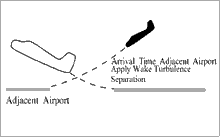
6-1-4. ADJACENT AIRPORT OPERATION
TERMINAL
WAKE TURBULENCE APPLICATION
The ATC facility having control jurisdiction at adjacent airports must separate arriving or departing IFR aircraft on a course that will cross the flight path of an aircraft requiring wake turbulence separation in accordance with the following:
- Heavy, large, or small behind super - 3 minutes.
- Heavy, large, or small behind heavy - 2 minutes.
- Small behind B757 - 2 minutes.

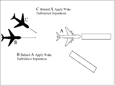
6-1-5. ARRIVAL MINIMA
TERMINAL
WAKE TURBULENCE APPLICATION
- Separate IFR aircraft landing behind an arriving aircraft to the same runway:
- Behind super:
- (a) Heavy or large - 3 minutes.
- (b) Small - 4 minutes.
- Behind heavy:
- (a) Heavy or large - 2 minutes.
- (b) Small - 3 minutes.
- Small behind B757 - 3 minutes.
- Behind super:
- Separate IFR aircraft landing behind an arriving aircraft to a parallel runway separated by less than 2,500 feet, or a crossing runway if projected flight paths will cross:
- Heavy, large, or small behind super - 3 minutes.
- Heavy, large, or small behind heavy - 2 minutes.
- Small behind B757 - 2 minutes.
Section 2. Initial Separation of Successive Departing Aircraft
6-2-1. MINIMA ON DIVERGING COURSES
interpretation 1Separate aircraft that will fly courses diverging by 45 degrees or more after departing the same or adjacent airports by use of one of the following minima:
- NOTE:
- 1. Consider known aircraft performance characteristics when applying initial separation to successive departing aircraft.
- 2. When one or both of the departure surfaces is a helipad, use the takeoff course of the helicopter as a reference, comparable to the centerline of a runway and the helipad center as the threshold.
- When aircraft will fly diverging courses:
- Immediately after takeoff - 1 minute until courses diverge. (See FIG 6-2-1.)
FIG 6-2-1 Minima on Diverging Courses 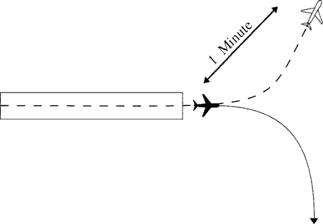
- Within 5 minutes after takeoff- 2 minutes until courses diverge. (See FIG 6-2-2.)
FIG 6-2-2 Minima on Diverging Courses 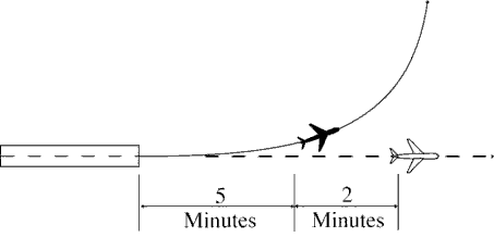
- Within 13 miles DME/ATD after takeoff - 3 miles until courses diverge. (See FIG 6-2-3.)
FIG 6-2-3 Minima on Diverging Courses 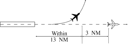
- Immediately after takeoff - 1 minute until courses diverge. (See FIG 6-2-1.)
- TERMINAL. Between aircraft departing in the same direction from different runways whose centerlines are parallel and separated by at least 3,500 feet, authorize simultaneous takeoffs when the aircraft will fly diverging courses immediately after takeoff. (See FIG 6-2-4.)
FIG 6-2-4 Minima on Diverging Courses 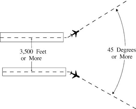
- TERMINAL. Between aircraft that will fly diverging courses immediately after takeoff from diverging runways: (See FIG 6-2-5.)
- Nonintersecting runways. Authorize simultaneous takeoffs when either of the following conditions exist:
- (a) The runways diverge by 30 degrees or more.
- (b) The distance between runway centerlines at and beyond the points where takeoffs begin is at least:
- (1) 2,000 feet and the runways diverge by 15 to 29 degrees inclusive.
- (2) 3,500 feet and the runways diverge by less than 15 degrees.
FIG 6-2-5 Minima on Diverging Courses 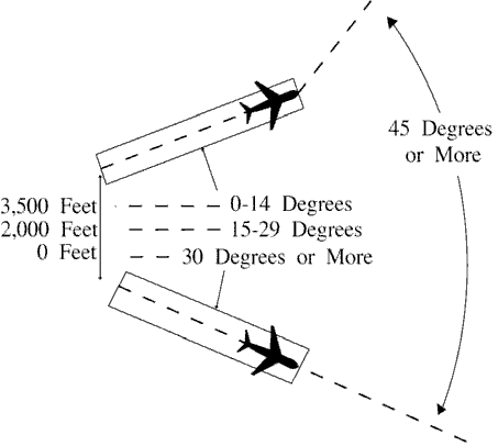
- Intersecting runways. Authorize takeoff of a succeeding aircraft when the preceding aircraft has passed the point of runway intersection, and
- (a) The runways diverge by 30 degrees or more. (See FIG 6-2-6.)
FIG 6-2-6 Minima on Diverging Courses 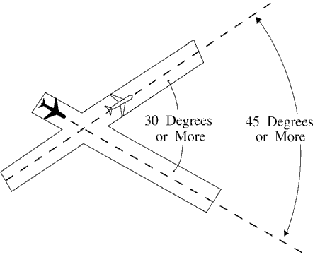
- (b) The runways diverge by 15 to 29 degrees inclusive and the preceding aircraft has commenced a turn. (See FIG 6-2-7.)
FIG 6-2-7 Minima on Diverging Courses 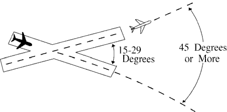
- (a) The runways diverge by 30 degrees or more. (See FIG 6-2-6.)
- Nonintersecting runways. Authorize simultaneous takeoffs when either of the following conditions exist:
6-2-2. MINIMA ON SAME COURSE
Separate aircraft that will fly the same course when the following aircraft will climb through the altitude assigned to the leading aircraft by using a minimum of 3 minutes until the following aircraft passes through the assigned altitude of the leading aircraft; or 5 miles between DME equipped aircraft; RNAV equipped aircraft using ATD; and between DME and ATD aircraft provided the DME aircraft is either 10,000 feet or below or outside of 10 miles from the DME NAVAID. (See FIG 6-2-8 and FIG 6-2-9.)
Section 3. Initial Separation of Departing and Arriving Aircraft
6-3-1. SEPARATION MINIMA
Separate a departing aircraft from an arriving aircraft making an instrument approach to the same airport by using one of the following minima until vertical or lateral separation is achieved:
- TERMINAL. When takeoff direction differs by at least 45 degrees from the reciprocal of the final approach course, the departing aircraft takes off before the arriving aircraft leaves a fix inbound not less than 4 miles from the airport.
- TERMINAL. When takeoff direction is other than in subparagraph a, the departing aircraft takes off so that it is established on a course diverging by at least 45 degrees from the reciprocal of the final approach course before the arriving aircraft leaves a fix inbound not less than 4 miles from the airport.
- TERMINAL. When the absence of an appropriate fix precludes the application of subparagraphs a or b and at airports where approach control service is not provided, the separation in subparagraphs d or e must be applied.
- When takeoff direction differs by at least 45 degrees from the reciprocal of the final approach course, the departing aircraft takes off 3 minutes before the arriving aircraft is estimated at the airport. (See FIG 6-3-1.)
FIG 6-3-1 Separation Minima 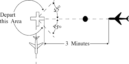
- When takeoff direction is other than in subparagraph d, the departing aircraft takes off so that it is established on a course diverging by at least 45 degrees from the reciprocal of the final approach course 5 minutes before the arriving aircraft is estimated at the airport or before it starts procedure turn. (See FIG 6-3-2 and FIG 6-3-3.)
FIG 6-3-2 Separation Minima 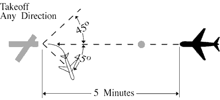
FIG 6-3-3 Separation Minima 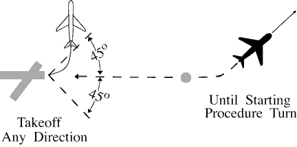
Section 4. Longitudinal Separation
6-4-1. APPLICATION
Separate aircraft longitudinally by requiring them to do one of the following, as appropriate:
- Depart at a specified time.
- Arrive at a fix at a specified time.
- PHRASEOLOGY
- CROSS (fix) AT OR BEFORE (time).
- CROSS (fix) AT OR AFTER (time).
- Hold at a fix until a specified time.
- Change altitude at a specified time or fix.
6-4-2. MINIMA ON SAME, CONVERGING, OR CROSSING COURSES
Separate aircraft on the same, converging, or crossing courses by an interval expressed in time or distance, using the following minima:
- When the leading aircraft maintains a speed at least 44 knots faster than the following aircraft - 5 miles between DME equipped aircraft; RNAV equipped aircraft using ATD; and between DME and ATD aircraft provided the DME aircraft is either 10,000 feet or below or outside of 10 miles from the DME NAVAID, or 3 minutes between other aircraft if, in either case, one of the following conditions is met:
- A departing aircraft follows a preceding aircraft which has taken off from the same or adjacent airport. (See FIG 6-4-1.)
FIG 6-4-1 Minima on Same Course 44 Knots or More Separation 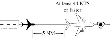
- A departing aircraft follows a preceding en route aircraft which has reported over a fix serving the departure airport. (See FIG 6-4-2.)
FIG 6-4-2 Minima on Converging Courses 44 Knots or More Separation 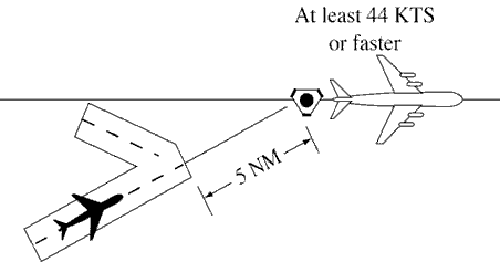
- An en route aircraft follows a preceding en route aircraft which has reported over the same fix. (See FIG 6-4-3.)
FIG 6-4-3 Minima on Crossing Courses 44 Knots or More Separation 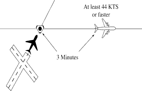
- A departing aircraft follows a preceding aircraft which has taken off from the same or adjacent airport. (See FIG 6-4-1.)
- When the leading aircraft maintains a speed at least 22 knots faster than the following aircraft - 10 miles between DME equipped aircraft; RNAV equipped aircraft using ATD; and between DME and ATD aircraft provided the DME aircraft is either 10,000 feet or below or outside of 10 miles from the DME NAVAID; or 5 minutes between other aircraft if, in either case, one of the following conditions exists:
- A departing aircraft follows a preceding aircraft which has taken off from the same or an adjacent airport. (See FIG 6-4-4.)
FIG 6-4-4 Minima on Same Course 22 Knots or More Separation 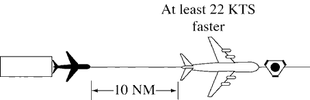
- A departing aircraft follows a preceding en route aircraft which has reported over a fix serving the departure airport. (See FIG 6-4-5.)
FIG 6-4-5 Minima on Converging Courses 22 Knots or More Separation 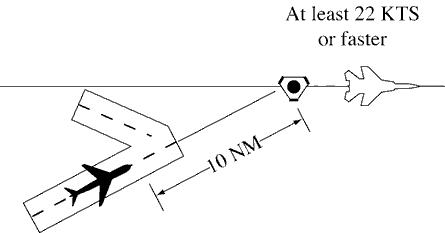
- An en route aircraft follows a preceding en route aircraft which has reported over the same fix. (See FIG 6-4-6.)
FIG 6-4-6 Minima on Crossing Courses 22 Knots or More Separation 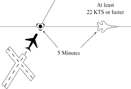
- A departing aircraft follows a preceding aircraft which has taken off from the same or an adjacent airport. (See FIG 6-4-4.)
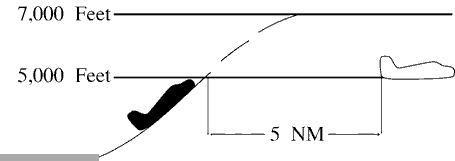
- When an aircraft is climbing or descending through the altitude of another aircraft:
- Between DME equipped aircraft; RNAV equipped aircraft using ATD; and between DME and ATD aircraft provided the DME aircraft is either 10,000 feet or below or outside of 10 miles from the DME NAVAID- 10 miles, if the descending aircraft is leading or the climbing aircraft is following. (See FIG 6-4-7 and FIG 6-4-8.)
FIG 6-4-7 Descending Through Another Aircraft's Altitude DME Separation 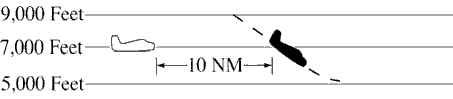
FIG 6-4-8 Climbing Through Another Aircraft's Altitude DME Separation 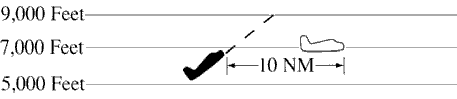
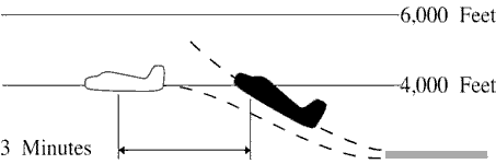
- Between other aircraft - 5 minutes, if all of the following conditions are met: (See FIG 6-4-9 and FIG 6-4-10.)
- (a) The descending aircraft is leading or climbing aircraft is following.
- (b) The aircraft are separated by not more than 4,000 feet when the altitude change started.
- (c) The change is started within 10 minutes after a following aircraft reports over a fix reported over by the leading aircraft or has acknowledged a clearance specifying the time to cross the same fix.
- Between RNAV aircraft that are operating along an RNAV route that is eight miles or less in width- 10 miles provided the following conditions are met:
- (a) The descending aircraft is leading or the climbing aircraft is following.
- (b) The aircraft were separated by not more than 4,000 feet when the altitude change started.
FIG 6-4-9 Descending Through Another Aircraft's Altitude Timed Separation 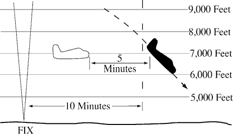
FIG 6-4-10 Climbing Through Another Aircraft's Altitude Timed Separation 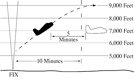
- Between DME equipped aircraft; RNAV equipped aircraft using ATD; and between DME and ATD aircraft provided the DME aircraft is either 10,000 feet or below or outside of 10 miles from the DME NAVAID- 10 miles, if the descending aircraft is leading or the climbing aircraft is following. (See FIG 6-4-7 and FIG 6-4-8.)
- When the conditions of subparagraphs a, b, or c cannot be met- 20 miles between DME equipped aircraft; RNAV equipped aircraft using ATD; and between DME and ATD aircraft provided the DME aircraft is either 10,000 feet or below or outside of 10 miles from the DME NAVAID; or 10 minutes between other aircraft. (See FIG 6-4-11, FIG 6-4-12, FIG 6-4-13, FIG 6-4-14, FIG 6-4-15, and FIG 6-4-16.)
FIG 6-4-11 Minima for Same Course Separation 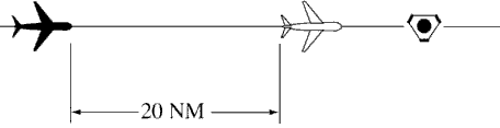
FIG 6-4-12 Minima for Crossing Courses Separation 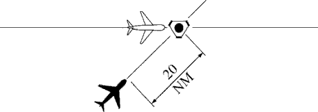
FIG 6-4-13 Minima for Same Course Separation 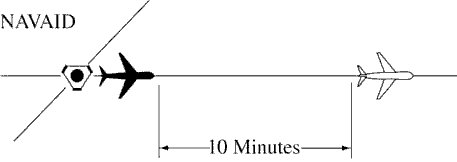
FIG 6-4-14 Minima for Crossing Courses Separation 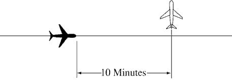
FIG 6-4-15 Climbing Through Another Aircraft's Altitude Separation 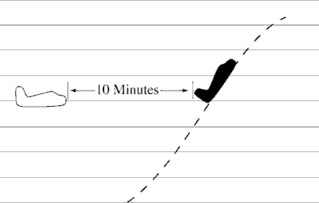
FIG 6-4-16 Descending Through Another Aircraft's Altitude Separation 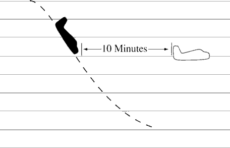
- Between aircraft, when one aircraft is using DME/ATD and the other is not- 30 miles if both the following conditions are met: (See FIG 6-4-17 and FIG 6-4-18.)
FIG 6-4-17 Minima for Same Course Separation 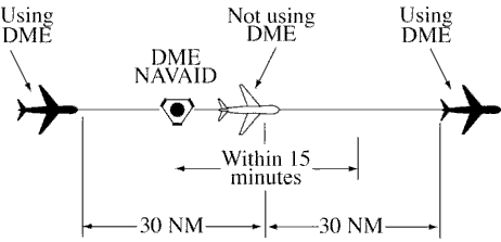
FIG 6-4-18 Minima for Crossing Courses Separation 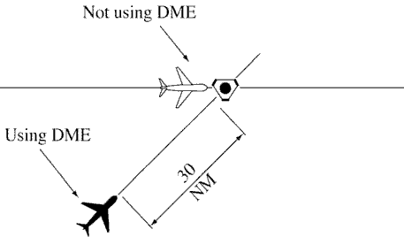
- The aircraft using DME/ATD derives distance information by reference to the same NAVAID or waypoint over which the aircraft not using DME/ATD has reported.
- The aircraft not using DME/ATD is within 15 minutes of the NAVAID.
6-4-3. MINIMA ON OPPOSITE COURSES
Separate aircraft traveling opposite courses by assigning different altitudes consistent with the approved vertical separation from 10 minutes before, until 10 minutes after they are estimated to pass. Vertical separation may be discontinued after one of the following conditions is met: (See FIG 6-4-19.)
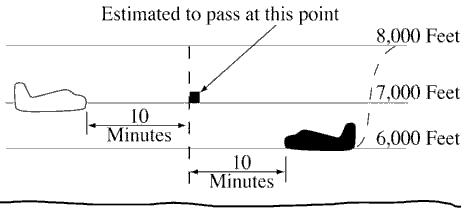
NOTE: RNAV route segments that have been expanded in the proximity to reference facilities for slant-range effect are not to be considered “expanded” for purposes of applying separation criteria in this paragraph.
- Both aircraft have reported passing NAVAIDs, DME fixes, or waypoints indicating they have passed each other.
(See FIG 6-4-20.)
FIG 6-4-20 Minima for Opposite Courses Separation 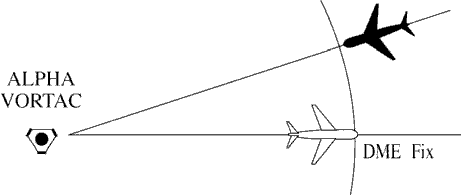
NOTE: It is not intended to limit application of this procedure only to aircraft operating in opposite directions along the same airway or radial. This procedure may also be applied to aircraft established on diverging airways or radials of the same NAVAID.
- Both aircraft have reported passing the same intersection/waypoint and they are at least 3 minutes apart.
- Two RNAV aircraft have reported passing the same position and are at least 8 miles apart if operating along a route that is 8 miles or less in width; or 18 miles apart if operating along any route segment that is greater than 8 miles in width; except that 30 miles must be applied if operating along that portion of any route segment defined by a navigation station requiring extended usable distance limitations beyond 130 miles.
- An aircraft utilizing RNAV and an aircraft utilizing VOR have reported passing the same position and the RNAV
aircraft is at least 4 miles beyond the reported position when operating along a route that is 8 miles or less in
width; 9 miles beyond the point when operating along any route segment that is greater than 8 miles in width;
except that 15 miles must be applied if operating along that portion of any route segment defined by a navigation
station requiring extended usable distance limitation beyond 130 miles; or 3 minutes apart whichever is greater.
NOTE: Except for GNSS-equipped aircraft /G, /L, /S, and /V, not on a random impromptu route, paragraph 5-5-1, Application, requires radar separation be provided to RNAV aircraft operating at and below FL450 on Q routes or random RNAV routes, excluding oceanic airspace.
6-4-4. SEPARATION BY PILOTS
When pilots of aircraft on the same course in direct radio communication with each other concur, you may authorize the following aircraft to maintain longitudinal separation of 10 minutes; or 20 miles between DME equipped aircraft; RNAV equipped aircraft using ATD; and between DME and ATD aircraft provided the DME aircraft is either 10,000 feet or below or outside of 10 miles from the DME NAVAID.
- PHRASEOLOGY
- MAINTAIN AT LEAST ONE ZERO MINUTES/TWO ZERO MILES SEPARATION FROM (ident).
6-4-5. RNAV AIRCRAFT ALONG VOR AIRWAYS/ROUTES
Advise the pilot to use DME distances when applying DME separation to an RNAV aircraft operating along VOR airways/routes.
- PHRASEOLOGY
- USE DME DISTANCES.
NOTE: ATD derived from area navigation devices having slant-range correction will not coincide with the direct DME readout.
Section 5. Lateral Separation
6-5-1. SEPARATION METHODS
Separate aircraft by one of the following methods:
- Clear aircraft on different airways or routes whose widths or protected airspace do not overlap.
- Clear aircraft below 18,000 to proceed to and report over or hold at different geographical locations determined visually or by reference to NAVAIDs.
- Clear aircraft to hold over different fixes whose holding pattern airspace areas do not overlap each other or other airspace to be protected.
- Clear departing aircraft to fly specified headings which diverge by at least 45 degrees.
6-5-2. MINIMA ON DIVERGING RADIALS
- Consider separation to exist between aircraft:
- Established on radials of the same NAVAID that diverge by at least 15 degrees when either aircraft is clear of the airspace to be protected for the other aircraft.
- With non-VOR/DME based navigational equipment established on tracks of the same waypoint that diverge by at least 15 degrees when either aircraft is clear of the airspace to be protected for the other aircraft.
FIG 6-5-1 Minima on Diverging Radials 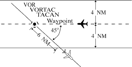
NOTE: The procedure may be applied to converging as well as diverging aircraft. (See FIG 6-5-1.) The aircraft depicted 6 miles from the NAVAID/waypoint would require vertical separation until reaching the 6-mile point. Reversing direction, the same aircraft would require vertical separation before passing the 6-mile point. Due to the nature of GPS equipment, issue crossing restrictions in reference to the next waypoint, since the pilot receives tracking “to” data rather than tracking “from” the last waypoint.
- Use TBL 6-5-1 and TBL 6-5-2 to determine the distance required for various divergence angles to clear the airspace to be protected. For divergence that falls between two values, use the lesser divergence value to obtain the distance.
TBL 6-5-1 Non-DME Divergence Distance Minima Divergence (Degrees) Distance (NM) 15 16 20 12 25 10 30 8 35 7 45 6 55 5 90 4 NOTE: This table is for non-DME application only. TBL 6-5-2 Divergence Distance Minima Divergence (Degrees) Distance (NM) Below FL 180 Fl 180 through FL 450 15 17 18 20 13 15 25 11 13 30 9 11 35 8 11 45 7 11 55 6 11 90 5 11 NOTE: This table is for DME application and compensates for DME slant-range error. NOTE: For altitudes of 3,000 feet or less above the elevation of the NAVAID, DME slant-range error is negligible and the values in TBL 6-5-1 may be used.
6-5-3. DME ARC MINIMA
Apply lateral DME separation by requiring aircraft using DME to fly an arc about a NAVAID at a specified distance using the following minima: (See FIG 6-5-2.)
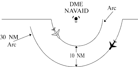
- Between different arcs about a NAVAID regardless of direction of flight:
- At 35 miles or less from the NAVAID- 10 miles.
- More than 35 miles from the NAVAID- 20 miles.
- Between an arc about a NAVAID and other airspace to be protected: (See FIG 6-5-3.)
FIG 6-5-3 DME Arc Minima 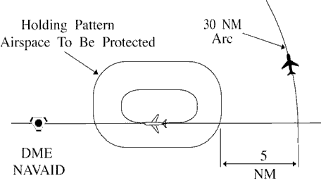
NOTE: The other airspace to be protected may be a MOA, a holding pattern, airway or route, ATCAA, Warning Area, Restricted Area, Prohibited Area, etc.
- At 35 miles or less from the NAVAID- 5 miles.
- More than 35 miles from the NAVAID- 10 miles.
- PHRASEOLOGY
- VIA (number of miles) MILE ARC (direction) OF (name of DME NAVAID).
6-5-4. MINIMA ALONG OTHER THAN ESTABLISHED AIRWAYS OR ROUTES
Protect airspace along other than established airways or routes as follows: (See FIG 6-5-4.)

- REFERENCE
- P/CG Term - Airway.
- P/CG Term - Route.
- Direct courses and course changes of 15 degrees or less:
- Via NAVAIDs or radials FL 600 and below- 4 miles on each side of the route to a point 51 miles from the NAVAID, then increasing in width on a 4 1/2 degree angle to a width of 10 miles on each side of the route at a distance of 130 miles from the NAVAID.
- Via degree-distance fixes for aircraft authorized under para 4-4-3, Degree-Distance Route Definition for
Military Operations.
- (a) Below FL180- 4 miles on each side of the route.
- (b) FL 180 to FL 600 inclusive- 10 miles on each side of the route.
- Via degree-distance fixes for RNAV flights above FL 450- 10 miles on each side of the route.
NOTE: Except for GNSS-equipped aircraft /G, /L, /S, and /V, not on a random impromptu route, Paragraph 5-5-1, Application, requires radar separation be provided to RNAV aircraft operating at and below FL450 on Q routes or random RNAV routes, excluding oceanic airspace.
- GNSS-equipped RNAV aircraft provided non-radar separation on random RNAV routes must be cleared via or
reported to be established on point-to-point route segments.
- (a) The points must be published NAVAIDs, waypoints, fixes, or airports recallable from the aircraft's navigation database. The points must be displayed on controller video maps or depicted on the controller chart displayed at the control position. The maximum distance between points must not exceed 500 miles.
- (b) Protect 4 miles either side of the route centerline.
- (c) Assigned altitudes must be at or above the highest MIA along the projected route segment being
flown, including the protected airspace of that route segment.
- EXAMPLE
- A pilot has filed a point-to-point route from XYZ to ABC at 13,000 feet. Departure procedures from the originating airport place the aircraft a significant distance from XYZ; however, the aircraft can establish itself along the route segment from XYZ to ABC. Ascertain when the pilot is established on the point-to-point route segment and at an altitude that meets or exceeds the highest MVA/MIA projected along the route of flight, then issue a clearance. “Verify when you are established on the XYZ to ABC route segment at or above 6,000 feet.”
- (d) When the GNSS aircraft is being provided radar service and is transitioning to non-radar airspace, provide clearance direct to the named point in non-radar airspace in accordance with subparagraphs a4(a) through (c).
- If transitioning between two random point-to-point routes, GNSS-equipped aircraft being provided non-radar
separation may be cleared via an impromptu route when the following conditions are met:
- (a) The impromptu route segment must not exceed the distance to the nearest available recallable fix/waypoint consistent with the direction of flight; and
- (b) Assigned altitudes must beat or above the highest MIA along the projected route segment being flown; and
- (c) Aircraft conducting the impromptu route must be separated vertically from other aircraft until established on the new point-to-point route.
- When course change is 16 degrees through 90 degrees, protect the airspace on the overflown side beginning at the
point where the course changes as follows: (See FIG 6-5-5.)
FIG 6-5-5 Overflown Side Minima 16 to 90 Degrees 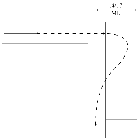
- Below FL 180- same as subparagraphs a1 or 2.
- FL 180 to FL 230 inclusive- 14 miles.
- Above FL230 to FL600 inclusive- 17miles.
- When course change is 91 degrees through 180 degrees, protect the airspace on the overflown side beginning at
the point where the course changes as follows: (See FIG 6-5-6.)
- Below FL 180- same as subparagraphs a1 or 2.
- FL 180 to FL 230 inclusive- 28 miles.
- Above FL230 to FL600 inclusive- 34miles.
FIG 6-5-6 Overflown Side Minima 91 to 180 Degrees 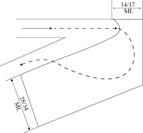
- After the course changes specified in subparagraphs b or c have been completed and the aircraft is back on course, the appropriate minima in subparagraph a may be used.
Section 6. Vertical Separation
6-6-1. APPLICATION
Assign an altitude to an aircraft after the aircraft previously at that altitude has reported leaving the altitude.
- PHRASEOLOGY
- REPORT LEAVING/REACHING (altitude/flight level).
- REPORT LEAVING ODD/EVEN ALTITUDES/FLIGHT LEVELS.
- (If aircraft is known to be operating below the lowest useable flight level),
- SAY ALTITUDE.
- or
- (If aircraft is known to be operating at or above the lowest useable flight level),
- SAY FLIGHT LEVEL.
- or
- If aircraft's position relative to the lowest useable flight level is unknown),
- SAY ALTITUDE OR FLIGHT LEVEL.
NOTE: Consider known aircraft performance characteristics, pilot furnished and/or Mode C detected information which indicate that climb/descent will not be consistent with the rates recommended in the AIM.
6-6-2. EXCEPTIONS
Assign an altitude to an aircraft only after the aircraft previously at that altitude has reported at or passing through another altitude separated from the first by the appropriate minimum when:
- Severe turbulence is reported.
- Aircraft are conducting military aerial refueling.
- The aircraft previously at the altitude has been:
- Issued a clearance permitting climb/descent at pilot's discretion.
- Cleared to CRUISE (altitude). However, do not use Mode C to effect separation with an aircraft on a cruise clearance.
NOTE: An aircraft assigned a cruise clearance is assigned a block of airspace from the minimum IFR altitude up to and including the assigned cruising altitude, and climb/descent within the block is at pilot's discretion. When the pilot verbally reports leaving an altitude in descent, he/she may not return to that altitude.
- REFERENCE
- P/CG Term - Cruise.
6-6-3. SEPARATION BY PILOTS
When pilots of aircraft in direct radio communication with each other during climb and descent concur, you may authorize the lower aircraft, if climbing, or the upper aircraft, if descending, to maintain vertical separation.
Section 7. Timed Approaches
6-7-1. APPLICATION
Timed approaches using either nonradar procedures or radar vectors to the final approach course may be used at airports served by a tower if the following conditions are met:
- NOTE:
- These procedures require NAVAIDs and standard/special instrument approach procedures or adequate radar coverage which permit an aircraft to:
- 1. Hold at a fix located on the approach course or to be radar vectored to the final approach course for a straight-in approach in accordance with the minima specified in para 6-7-5, Interval Minima.
- 2. Proceed in the direction of the airport along the approach course crossing the holding/approach fix at a specified altitude if required.
- 3. Continue descent for an approach to destination airport.
- Direct communication is maintained with the aircraft until the pilot is instructed to contact the tower.
- If more than one missed approach procedure is available, none require course reversal.
- If only one missed approach procedure is available, the following conditions are met:
- Course reversal is not required.
- Reported ceiling and visibility are equal to or greater than the highest prescribed circling mini- mums for the instrument approach procedure in use.
NOTE: Determination of whether or not an existing ceiling meets minima is accomplished by comparing MDA (MSL) with ceiling (AGL) plus the airport elevation.
6-7-2. APPROACH SEQUENCE
When an aircraft passes the final approach fix inbound (nonprecision approach) or the outer marker or the fix used in lieu of the outer marker inbound (precision approach), issue clearances for a succeeding timed approach in accordance with the following:
- REFERENCE
- FAA Order JO 7110.65, Para 5-9-5, Approach Separation Responsibility.
- FAA Order JO 7110.65, Para 6-7-4, Level Flight Restriction.
- FAA Order JO 7110.65, Para 6-7-7, Missed Approaches.
- Clear the succeeding aircraft for approach, to descend to the altitude vacated by the preceding aircraft, and to leave the final approach fix inbound (nonprecision approach) or the outer marker or the fix used in lieu of the outer marker inbound (precision approach) at a specified time; or when using radar to sequence and position aircraft on the final approach course, vector aircraft to cross the final approach fix/outer marker or the fix used in lieu of the outer marker in compliance with para 6-7-5, Interval Minima.
FIG 6-7-1 Timed Approach Procedures Using ILS and Longitudinal Separation Only 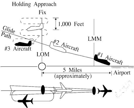
NOTE: FIG 6-7-1 depicts the application of timed approach procedures using an ILS and applying longitudinal separation only. Using an interval of 2 minutes between successive approaches, the #1 and #2 aircraft have already passed the outer locator (LOM) on final approach, and the #3 aircraft has been cleared for approach and to depart the LOM 2 minutes after the #2 aircraft reported leaving the LOM inbound on final approach. After aircraft in the approach sequence depart the holding/approach fix (LOM) inbound, vertical separation is no longer provided and longitudinal separation is utilized.
FIG 6-7-2 Timed Approach Procedures Using a Bearing on an NDB and Longitudinal and Vertical Separation 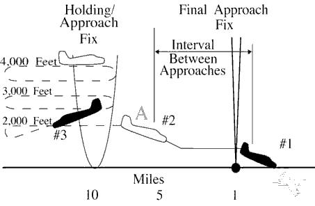
- If an alternative missed approach procedure is not available and weather conditions are less than required by para 6-7-1, Application, subparagraph c, clear the succeeding aircraft for an approach when the preceding aircraft has landed or canceled its IFR flight plan.
NOTE: FIG 6-7-2 depicts the application of timed approach procedures using a holding/approach fix on a bearing of an NDB and applying a combination of longitudinal and vertical separation. The #3 aircraft has been instructed to descend to 2,000 after the #2 aircraft has reported departing the holding/approach fix inbound and leaving 2,000 at point A. The #2 aircraft has departed the holding/approach fix inbound at the designated time, maintaining 2,000 until cleared for approach at point A. The #1 aircraft has been sighted, enabling the controller to issue approach clearance to the #2 aircraft at point A.
- Release the aircraft to the tower before it reaches the final approach fix.
6-7-3. SEQUENCE INTERRUPTION
Interrupt the established timed approach sequence if necessary to allow an aircraft to execute a different type of approach.
6-7-4. LEVEL FLIGHT RESTRICTION
If the weather report indicates an aircraft will be in IFR conditions over the final approach fix (nonprecision approach) or the outer marker or the fix used in lieu of the outer marker (precision approach) when para 6-7-2, Approach Sequence, subparagraph b is applied, clear the second aircraft for an approach early enough to allow at least 1 minute of level flight before crossing the final approach fix/outer marker or the fix used in lieu of the outer marker.
6-7-5. INTERVAL MINIMA
- Except as provided in subparagraph b, use a 2-minute or a 5-mile radar interval as the minimum between successive approaches.
- REFERENCE
- FAA Order JO 7110.65, Para 5-9-5, Approach Separation Responsibility.
- FAA Order JO 7110.65, Para 6-7-1, Application.
- FAA Order JO 7110.65, Para 6-7-2, Approach Sequence.
WAKE TURBULENCE APPLICATION
- Use the following time or radar interval as the minimum interval:
- Behind super:
- (a) Heavy - 3 minutes or 6 miles.
- (b) Large - 3 minutes or 7 miles.
- (c) Small - 4 minutes or 8 miles.
- Small behind heavy - 3 minutes or 6 miles.
- Behind super:
- Increase the interval, as necessary, taking into account the:
- Relative speeds of the aircraft concerned.
- Existing weather conditions.
- Distance between the approach fix and the airport.
- Type of approach being made.
6-7-6. TIME CHECK
Issue a time check to an aircraft before specifying a time to leave the approach fix inbound unless the aircraft is vectored to the final approach course.
6-7-7. MISSED APPROACHES
- If weather conditions are such that an aircraft will likely miss an approach, issue an alternative missed approach procedure to the next aircraft.
- If an aircraft misses an approach, allow the next aircraft to continue the approach if it has been assigned an alternative missed approach procedure. Retain radar control or hold any remaining aircraft at assigned altitudes until traffic conditions permit the issuance of approach clearances.
- When para 6-7-2, Approach Sequence, subparagraph b is applied and the first aircraft misses an approach, retain radar control or clear the second aircraft to maintain the last assigned altitude (minimum holding altitude) and return to the holding/approach fix to hold until traffic conditions permit the issuance of approach clearances.