Section 1. General
8-1-1. ATC SERVICE
Provide air traffic control service in oceanic controlled airspace in accordance with the procedures in this chapter except when other procedures/minima are prescribed in a directive or a letter of agreement.
8-1-2. OPERATIONS IN OFFSHORE AIRSPACE AREAS
Provide air traffic control service in offshore airspace areas in accordance with procedures and minima in this chapter. For those situations not covered by this chapter, the provisions in this Order must apply.
8-1-3. VFR FLIGHT PLANS
VFR flights in Oceanic FIRs may be conducted in meteorological conditions equal to or greater than those specified in 14 CFR Section 91.155, Basic VFR weather minimums. Operations on a VFR flight plan are permitted only between sunrise and sunset and only within:
- Miami, Houston, and San Juan Oceanic Control Areas (CTAs) below FL 180.
- Within the Oakland FIR when operating less than 100 NM seaward from the shoreline within controlled airspace.
- All Oceanic FIR airspace below the Oceanic CTAs.
8-1-4. TYPES OF SEPARATION
Separation must consist of at least one of the following:
- Vertical separation;
- Horizontal separation, either;
- Longitudinal; or
- Lateral;
- Composite separation;
- Radar separation, as specified in Chapter 5, Radar, where radar coverage is adequate.
8-1-5. ALTIMETER SETTING
Within oceanic control areas, unless directed and/or charted otherwise, altitude assignment must be based on flight levels and a standard altimeter setting of 29.92 inches Hg.
8-1-6. RECEIPT OF POSITION REPORTS
When a position report affecting separation is not received, take action to obtain the report no later than 10 minutes after the control estimate, unless otherwise specified.
8-1-7. OCEANIC ERROR REPORT PROCEDURES
FAA Order 7210.632.82 establishes procedures for reporting Gross Navigation Errors (GNE), height errors, time(longitudinal) errors, intervention, and Special Area of Operations (SAO) verification in oceanic airspace. This data is needed for risk modeling activities to support separation standard reductions.
8-1-8. USE OF CONTROL ESTIMATES
Control estimates are the estimated position of aircraft, with reference to time as determined by the ATC automation system in use or calculated by the controller using known wind patterns, previous aircraft transit times, pilot progress reports, and pilot estimates. These estimates may be updated through the receipt of automated position reports and/or manually updated by the controller. Control estimates must be used when applying time-based separation minima.
8-1-9. RVSM OPERATIONS
Controller responsibilities for non-RVSM aircraft operating in RVSM airspace must include but not be limited to the following:
- Ensure non-RVSM aircraft are not permitted in RVSM airspace unless they meet the criteria of excepted aircraft and are previously approved by the operations supervisor/CIC.
- In addition to those aircraft listed in Chapter 2, Section 1, Paragraph 2-1-29 RVSM Operations in this order, the following aircraft operating within oceanic airspace or transiting to/from oceanic airspace are excepted:
- Aircraft being initially delivered to the State of Registry or Operator;
- Aircraft that was formerly RVSM approved but has experienced an equipment failure and is being flown to a maintenance facility for repair in order to meet RVSM requirements and/or obtain approval;
- Aircraft being utilized for mercy or humanitarian purposes;
- Within the Oakland, Anchorage, and Arctic FIR's, an aircraft transporting a spare engine mounted under the wing.
- (a) These exceptions are accommodated on a workload or traffic-permitting basis.
- (b) All other requirements contained in paragraph 2-1-29 are applicable to this section.
Section 2. Coordination
8-2-1. GENERAL
ARTCCs must:
- Forward to appropriate ATS facilities, as a flight progresses, current flight plan and control information.
- Coordinate flight plan and control information in sufficient time to permit the receiving facility to analyze the data and to effect any necessary additional coordination. This may be specified in a letter of agreement.
- Coordinate with adjacent ATS facilities when airspace to be protected will overlap the common boundary.
- Forward revisions of estimates of 3 minutes or more to the appropriate ATS facility.
- Coordinate with adjacent facilities on IFR and VFR flights to ensure the continuation of appropriate air traffic services.
8-2-2. TRANSFER OF CONTROL AND COMMUNICATIONS
- Only one air traffic control unit must control an aircraft at any given time.
- The control of an aircraft must be transferred from one control unit to another at the time the aircraft is estimated to cross the control boundary or at such other point or time agreed upon by the two units.
- The transferring unit must forward to the accepting unit any changed flight plan or control data which are pertinent to the transfer.
- The accepting unit must notify the transferring unit if it is unable to accept control under the terms specified, or it must specify the changes or conditions required so that the aircraft can be accepted.
- The accepting unit must not alter the clearance of an aircraft that has not yet reached the transfer of control point without the prior approval of the transferring unit.
- Where nonradar separation minima are being applied, the transfer of air-ground communications with an aircraft must be made 5 minutes before the time at which the aircraft is estimated to reach the boundary unless otherwise agreed to by the control and/or communication units concerned.
8-2-3. AIR TRAFFIC SERVICES INTERFACILITY DATA COMMUNICATIONS (AIDC)
Where interfacility data communications capability has been implemented, its use for ATC coordination should be accomplished in accordance with regional Interface Control Documents, and supported by letters of agreement between the facilities concerned.
Section 3. Longitudinal Separation
8-3-1. APPLICATION
- Longitudinal separation must be applied so that the spacing between the estimated positions of the aircraft being separated is never less than a prescribed minimum.
NOTE: Consider separation to exist when the estimated positions of the aircraft being separated are never less than a prescribed minimum.
- In situations where one aircraft requires a different time-based longitudinal standard than another, apply the larger of the two standards between the aircraft concerned.
- Longitudinal separation expressed in distance may be applied as prescribed in Chapter 6, Nonradar.
- In situations where an update to a control estimate indicates that the minimum being applied no longer exists, controllers must ensure that separation is reestablished. Issue traffic information as necessary.
8-3-2. SEPARATION METHODS
-
For the purpose of application of longitudinal separation, the terms same track must be considered identical to
same course, reciprocal tracks must be considered identical to reciprocal courses, and crossing tracks, must be
considered identical to crossing courses.
NOTE: Refer to paragraph 1-2-2, Course Definitions.
-
Separate aircraft longitudinally in accordance with the following:
-
Same track. Ensure that the estimated spacing between aircraft is not less than the applicable minimum
required. (See FIG 8-3-1.)
FIG 8-3-1 Same Courses 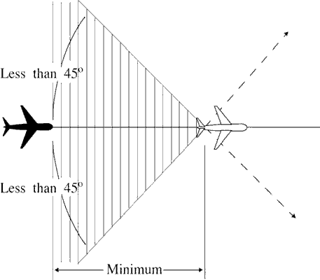
-
Crossing tracks. Ensure that the estimated spacing at the point of intersection is not less than the
applicable minimum required. (See FIG 8-3-2.)
FIG 8-3-2 Crossing Courses 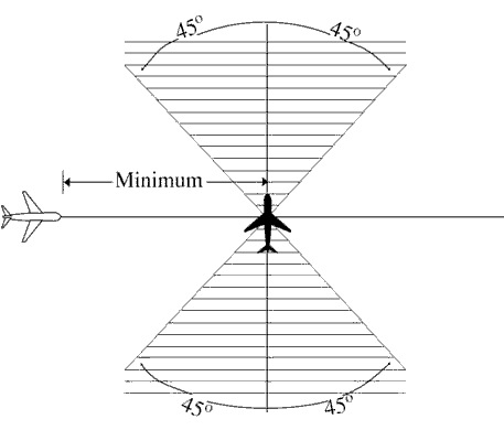
-
Reciprocal tracks:
-
(a) Ensure that aircraft are vertically separated for a time interval equal to the applicable minimum
required before and after the aircraft are estimated to pass. (See FIG 8-3-3.)
FIG 8-3-3 Reciprocal Courses 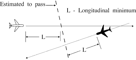
-
(b) Vertical separation may be discontinued after one of the following conditions is met:
-
(1) Both aircraft have reported passing a significant point and the aircraft are separated by at least
the applicable minimum required for the same direction longitudinal spacing; (See FIG 8-3-4.) or
FIG 8-3-4 Vertical Separation 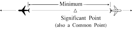
- (2) Both aircraft have reported passing ground-based NAVAIDs or DME fixes indicating that they have passed each other.
-
(1) Both aircraft have reported passing a significant point and the aircraft are separated by at least
the applicable minimum required for the same direction longitudinal spacing; (See FIG 8-3-4.) or
-
(a) Ensure that aircraft are vertically separated for a time interval equal to the applicable minimum
required before and after the aircraft are estimated to pass. (See FIG 8-3-3.)
-
Same track. Ensure that the estimated spacing between aircraft is not less than the applicable minimum
required. (See FIG 8-3-1.)
8-3-3. MACH NUMBER TECHNIQUE
The use of Mach number technique allows for the application of reduced longitudinal separation minima. The following conditions must be met when the Mach number technique is being applied:
- Aircraft Types: Turbojet aircraft only.
- Routes:
- The aircraft follow the same track or continuously diverging tracks, and
- The aircraft concerned have reported over a common point; or
- If the aircraft have not reported over a common point, the appropriate time interval being applied between aircraft exists and will exist at the common point; or,
- If a common point does not exist, the appropriate time interval being applied between aircraft exists and will exist at significant points along each track.
- Altitudes: The aircraft concerned are in level, climbing or descending flight.
- Mach Number Assignment:
- A Mach number (or, when appropriate, a range of Mach numbers) must be issued to each aircraft unless otherwise prescribed on the basis of ICAO regional agreement.
- NOTE:
- 1. The application of Mach number technique requires pilots to strictly adhere to the last assigned Mach number (or range of Mach numbers), even during climbs and descents, unless revised by ATC. Turbojet aircraft must request ATC approval before making any changes. If it is essential to make an immediate temporary change in the Mach number (e.g., due to turbulence), ATC must be notified as soon as possible that such a change has been made.
- 2. When it is necessary to issue crossing restrictions to ensure the appropriate time interval, it may be impossible for an aircraft to comply with both the clearance to meet the crossing restrictions and the clearance to maintain a single, specific Mach number.
- REFERENCE
- ICAO DOC 9426-AN/924, Part II, Section 2, Para 2.3.4, Para 2.4.7, and Para 2.5.3.
- EXAMPLE
- “Maintain Mach point eight four or greater.”
- “Maintain Mach point eight three or less.”
- “Maintain Mach point eight two or greater; do not exceed Mach point eight four.”
- A Mach number (or, when appropriate, a range of Mach numbers) must be issued to each aircraft unless otherwise prescribed on the basis of ICAO regional agreement.
- Longitudinal Minima: When the Mach number technique is applied, minimum longitudinal separation must be:
- 10 minutes, provided that:
- (a) The preceding aircraft maintains a Mach number equal to, or greater than that maintained by the following aircraft; or
- (b) When the following aircraft is faster than the preceding aircraft, at least 10 minutes exists until another form of separation is achieved; or
- Between 9 and 5 minutes inclusive, provided that the preceding aircraft is maintaining a Mach number greater than the following aircraft in accordance with the following:
- (a) 9 minutes, if the preceding aircraft is Mach 0.02 faster than the following aircraft;
- (b) 8 minutes, if the preceding aircraft is Mach 0.03 faster than the following aircraft;
- (c) 7 minutes, if the preceding aircraft is Mach 0.04 faster than the following aircraft;
- (d) 6 minutes, if the preceding aircraft is Mach 0.05 faster than the following aircraft;
- (e) 5 minutes, if the preceding aircraft is Mach 0.06 faster than the following aircraft.
NOTE: A “rule-of-thumb” may be applied to assist in providing the required estimated spacing over the oceanic exit point when either conflict probe is not in use or when requested by another facility. This rule-of-thumb can be stated as follows: For each 600 NM in distance between the entry and exit points of the area where the Mach Number Technique is used, add 1 minute for each 0.01 difference in Mach number for the two aircraft concerned to compensate for the fact that the second aircraft is overtaking the first aircraft. (See TBL 8-3-1.)
- 10 minutes, provided that:
| Difference in Mach | Distance to Fly and Separation (in Minutes) Required at Entry Point | ||||
|---|---|---|---|---|---|
| 001-600 NM | 601-1200 NM | 1201-1800 NM | 1801-2400 NM | 2401-3000 NM | |
| 0.01 | 11 | 12 | 13 | 14 | 15 |
| 0.02 | 12 | 14 | 16 | 18 | 20 |
| 0.03 | 13 | 16 | 19 | 22 | 25 |
| 0.04 | 14 | 18 | 22 | 26 | 30 |
| 0.05 | 15 | 20 | 25 | 30 | 35 |
| 0.06 | 16 | 22 | 28 | 34 | 40 |
| 0.07 | 17 | 24 | 31 | 38 | 45 |
| 0.08 | 18 | 26 | 34 | 42 | 50 |
| 0.09 | 19 | 28 | 37 | 46 | 55 |
| 0.10 | 20 | 30 | 40 | 50 | 60 |
Section 4. Lateral Separation
8-4-1. APPLICATION
Separate aircraft by assigning different flight paths whose widths or protected airspace do not overlap.
Within that portion of the Gulf of Mexico Low Offshore airspace, use 12 NM between aircraft whose flight paths are defined by published Grid System waypoints.
- NOTE:
- 1. The Grid System is defined as those waypoints contained within the Gulf of Mexico Low Offshore airspace and published on the IFR Vertical Flight Reference Chart.
- 2. Lateral separation minima is contained in:
- Section 7, North Atlantic ICAO Region.
- Section 8, Caribbean ICAO Region.
- Section 9, Pacific ICAO Region.
- Section 10, North American ICAO Region - Arctic CTA.
8-4-2. SEPARATION METHODS
Lateral separation exists for:
- Nonintersecting flight paths:
- When the required distance is maintained between the flight paths; or (See FIG 8-4-1.)
FIG 8-4-1 Separation Methods 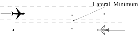
- When reduced route protected airspace is applicable, and the protected airspace of the flight paths do not overlap; or (See FIG 8-4-2.)
FIG 8-4-2 Separation Methods 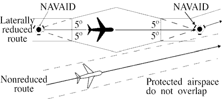
- When aircraft are crossing an oceanic boundary and are entering an airspace with a larger lateral minimum than the airspace being exited; and
- (a) The smaller separation exists at the boundary; and
- (b) Flight paths diverge by 15° or more until the larger minimum is established. (See FIG 8-4-3.)
FIG 8-4-3 Separation Methods 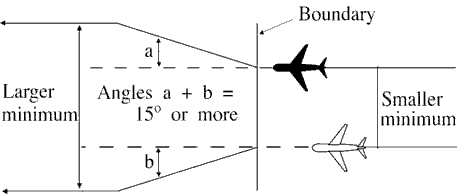
- When the required distance is maintained between the flight paths; or (See FIG 8-4-1.)
- Intersecting flight paths with constant and same width protected airspace when either aircraft is at or beyond a distance equal to the applicable lateral separation minimum measured perpendicular to the flight path of the other aircraft. (See FIG 8-4-4.)
FIG 8-4-4 Separation Methods 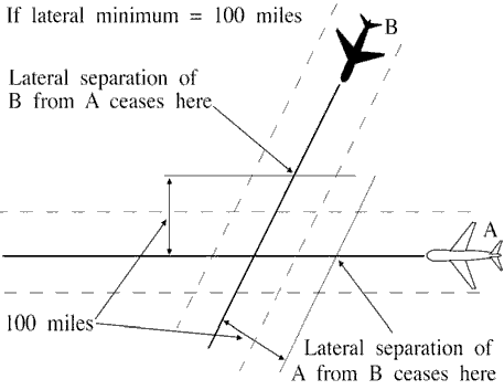
- Intersecting flight paths with constant but different width protected airspace when either aircraft is at or beyond a distance equal to the sum of the protected airspace of both flight paths measured perpendicular to the flight path of the other aircraft. (See FIG 8-4-5.)
FIG 8-4-5 Separation Methods 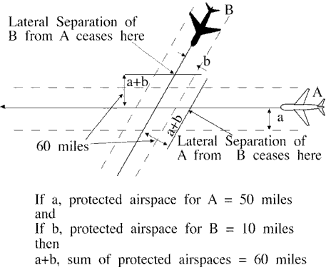
- Intersecting flight paths with variable width protected airspace when either aircraft is at or beyond a distance equal to the sum of the protected airspace of both flight paths measured perpendicular to the flight path of the other aircraft. Measure protected airspace for each aircraft perpendicular to its flight path at the first point or the last point, as applicable, of protected airspace overlap.
NOTE: In FIG 8-4-5, the protected airspace for westbound flight A is distance “a” (50 miles), and for southwest bound flight B, distance “b” (10 miles). Therefore, the sum of distances “a” and “b”; i.e., the protected airspace of Aircrafts A and B, establishes the lateral separation minimum (60 miles) applicable for either flight relevant to the other.
FIG 8-4-6 Separation Methods 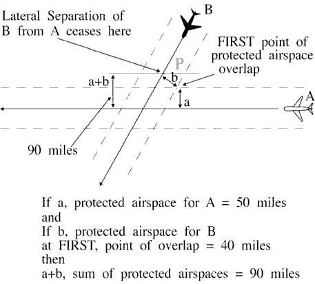
NOTE: (See FIG 8-4-6.) At the first point of protected airspace overlap, the protected airspace for westbound flight A is distance “a” (50 miles), and for southbound flight B, distance “b” (40 miles). The sum of distances “a” and “b” (90 miles) establishes the lateral separation minimum applicable in this example for either flight as it approaches the intersection. For example, Aircraft B should be vertically separated from Aircraft A by the time it reaches point “p.”
FIG 8-4-7 Separation Methods 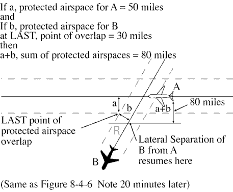
NOTE: (See FIG 8-4-7.) Distance “a” (50 miles) and “b” (30 miles) are determined at the last point of protected airspace overlap. The sum of the distances “a” and “b” (80 miles) establishes the lateral separation minima applicable for either flight after it passes beyond the intersection. For example, Aircraft B could be cleared to, or through, Aircraft A's altitude after passing point “r.”
8-4-3. REDUCTION OF ROUTE PROTECTED AIRSPACE
When routes have been satisfactorily flight checked and notice has been given to users, reduction in route protected airspace may be made as follows:
- Below FL240, reduce the width of the protected airspace to 5 miles on each side of the route centerline to a distance of 57.14 miles from the NAVAID, then increasing in width on a 5° angle from the route centerline, measured at the NAVAID, to the maximum width allowable within the lateral minima; for example, 50 miles of protected airspace on each side of centerline; i.e., a lateral minimum of 100 miles. (See FIG 8-4-8.)
FIG 8-4-8 Reduction of Route Protected Airspace 
- At and above FL 240, reduce the width of the protected airspace to 10 miles on each side of the route centerline to a distance of 114.29 miles from the NAVAID, then increasing in width on a 5_ angle from the route centerline, as measured at the NAVAID, to the maximum width allowable within the lateral minima; for example, 60 miles of protected airspace on each side of the centerline; i.e., a lateral separation minimum of 120 miles. (See FIG 8-4-9.)
FIG 8-4-9 Reduction of Route Protected Airspace 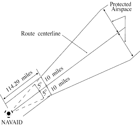
8-4-4. TRACK SEPARATION
Apply track separation between aircraft by requiring aircraft to fly specified tracks or radials and with specified spacings as follows:
- Same NAVAID:
- VOR/VORTAC/TACAN. Consider separation to exist between aircraft established on radials of the same NAVAID that diverge by at least 15 degrees when either aircraft is clear of the airspace to be protected for the other aircraft. Use TBL 8-4-1 to determine the flight distance required for various divergence angles and altitudes to clear the airspace to be protected. (See FIG 8-4-10.)
TBL 8-4-1 Divergence-Distance Minima VOR/VORTAC/TACAN Divergence (degrees) Distance (mile) FL 230 and below Fl 240 through FL 450 15-25 17 18 26-35 11 13 36-90 8 11 Note This table compensates for DME slant range error. FIG 8-4-10 Track Separation VOR 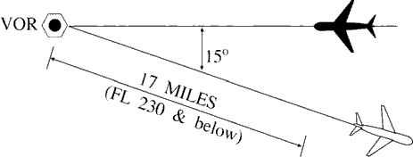
- NDB:
- (a) Consider separation to exist between aircraft established on tracks of the same NAVAID that diverge by at least 30 degrees and one aircraft is at least 15 miles from the NAVAID. This separation must not be used when one or both aircraft are inbound to the aid unless the distance of the aircraft from the facility can be readily determined by reference to the NAVAID. Use TBL8-4-2 to determine the flight distance required for various divergence angles to clear the airspace to be protected. For divergence that falls between two values, use the lesser value to obtain the distance. (See FIG 8-4-11.)
TBL 8-4-2 Divergence-Distance Minima (NDB) Divergence (degrees) Distance (mile) FL 230 and below Fl 240 through FL 450 30 15 17 45 13 14 60 9 10 75 7 8 90 6 7 Note This table compensates for DME slant range error. FIG 8-4-11 Track Separation NDB 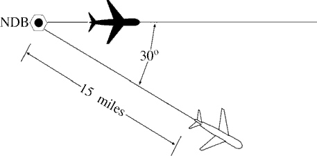
- (b) Clear aircraft navigating on NDB facilities in accordance with para 2-5-2, NAVAID Terms.
- (a) Consider separation to exist between aircraft established on tracks of the same NAVAID that diverge by at least 30 degrees and one aircraft is at least 15 miles from the NAVAID. This separation must not be used when one or both aircraft are inbound to the aid unless the distance of the aircraft from the facility can be readily determined by reference to the NAVAID. Use TBL8-4-2 to determine the flight distance required for various divergence angles to clear the airspace to be protected. For divergence that falls between two values, use the lesser value to obtain the distance. (See FIG 8-4-11.)
- VOR/VORTAC/TACAN. Consider separation to exist between aircraft established on radials of the same NAVAID that diverge by at least 15 degrees when either aircraft is clear of the airspace to be protected for the other aircraft. Use TBL 8-4-1 to determine the flight distance required for various divergence angles and altitudes to clear the airspace to be protected. (See FIG 8-4-10.)
- Different NAVAIDs: Separate aircraft using different navigation aids by assigning tracks so that their protected airspace does not overlap. (See FIG 8-4-12.)
FIG 8-4-12 Track Separation Different NAVAIDs 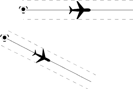
- Dead Reckoning (DR):
- Consider separation to exist between aircraft established on tracks that diverge by at least 45 degrees when one aircraft is at least 15 miles from the point of intersection of the tracks. This point may be determined either visually or by reference to a ground-based navigation aid. (See FIG 8-4-13.)
FIG 8-4-13 Track Separation Dead Reckoning 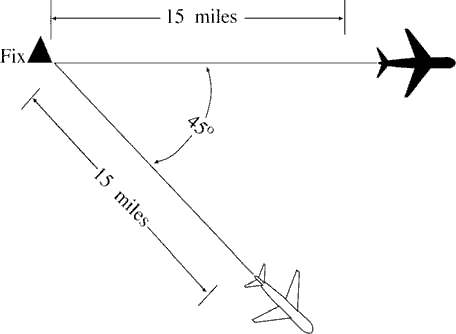
- Consider separation to exist between aircraft established on tracks that diverge by at least 45 degrees when one aircraft is at least 15 miles from the point of intersection of the tracks. This point may be determined either visually or by reference to a ground-based navigation aid. (See FIG 8-4-13.)
Section 5. Offshore/Oceanic Transition Procedures
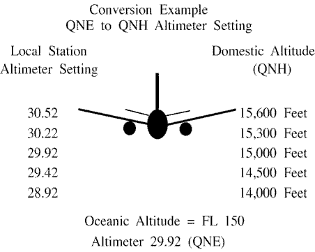
8-5-1. ALTITUDE/FLIGHT LEVEL TRANSITION
When vertical separation is applied between aircraft crossing the offshore/oceanic airspace boundary below FL 180, control action must be taken to ensure that differences between the standard altimeter setting (QNE) and local altimeter setting (QNH) do not compromise separation. (See FIG 8-5-1.)
8-5-2. COURSE DIVERGENCE
When aircraft are entering oceanic airspace, separation will exist in oceanic airspace when:
- Aircraft are established on courses that diverge by at least 15 degrees until oceanic lateral separation is established, and
- The aircraft are horizontally radar separated and separation is increasing at the edge of known radar coverage.
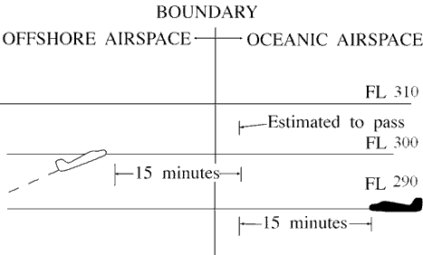
8-5-3. OPPOSITE DIRECTION
When transitioning from an offshore airspace area to oceanic airspace, an aircraft may climb through opposite direction oceanic traffic provided vertical separation above that traffic is established:
- Before the outbound crosses the offshore/ oceanic boundary; and
- 15 minutes before the aircraft are estimated to pass. (See FIG 8-5-2.)
8-5-4. SAME DIRECTION
When transitioning from an offshore airspace area to oceanic airspace or while within oceanic airspace, apply 5 minutes minimum separation when a following aircraft on the same course is climbing through the altitude of the preceding aircraft if the following conditions are met:
- The preceding aircraft is level at the assigned altitude and is maintaining a speed equal to or greater than the following aircraft; and
- The minimum of 5 minutes is maintained between the preceding and following aircraft; and
- The following aircraft is separated by not more than 4,000 feet from the preceding aircraft when the climb clearance is issued; and
- The following aircraft commences climb within 10 minutes after passing:
- An exact reporting point (DME fix or intersection formed from NAVAIDs) which the preceding aircraft has reported; or
- A radar observed position over which the preceding aircraft has been observed; and
- The following aircraft is in direct communication with air traffic control until vertical separation is established. (See FIG 8-5-3.)

8-5-5. RADAR IDENTIFICATION APPLICATION
Radar separation standards may be applied between radar identified aircraft and another aircraft not yet identified that is in transit from oceanic airspace or non-radar offshore airspace into an area of known radar coverage where radar separation is applied provided:
- Direct radio communications is maintained with one of the aircraft involved and there is an ability to communicate with the other;
- The transiting aircraft is RNAV equipped;
- The performance of the radar/system is adequate;
- REFERENCE
- FAA Order JO 7110.65, Para 5-1-1, Presentation and Equipment Performance.
- Flight data on the aircraft that has not been radar identified indicate that it is equipped with a standard transponder and there is no known information that the transponder is not operating;
- Radar separation standards are maintained between the radar identified aircraft and any other observed targets until the transitioning aircraft is radar identified or non-radar separation is established;
- The facility has identified areas of known radar coverage, incorporated those areas into facility standard operating procedures (SOP), and provided training to the controllers.
- This procedure is also applicable to aircraft in transit from oceanic airspace into Guam Control Area (CTA), San Juan CTA and Honolulu CTA radar coverage areas.
- EXCEPTION: This procedure is not authorized if there is insufficient time for the controller to establish other approved separation in the event of a delay or inability to establish radar identification of the transiting aircraft taking into consideration factors such as aircraft performance characteristics, type, and speed; weather, traffic conditions; workload; frequency congestion; etc.
Section 6. Separation from Airspace Reservations
8-6-1. TEMPORARY STATIONARY AIRSPACE RESERVATIONS
Separate aircraft from a temporary stationary reservation by one of two methods:
- Laterally: Clear aircraft so that the protected airspace along the route of flight does not overlap the geographical area of the stationary reservation. (See FIG 8-6-1.)
FIG 8-6-1 Temporary Stationary Airspace Reservations Lateral Separation 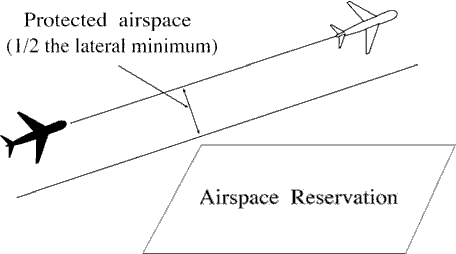
- Vertically: Clear aircraft so that vertical separation exists while the aircraft is within a geographical area defined as the stationary reservation plus a buffer around the perimeter equivalent to one-half the lateral separation minimum. (See FIG 8-6-2.)
FIG 8-6-2 Temporary Stationary Airspace Reservations Vertical Separation 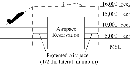
8-6-2. REFUSAL OF AVOIDANCE CLEARANCE
If a pilot refuses to accept a clearance to avoid a reservation, inform him/her of the potential hazard, advise him/her that services will not be provided while the flight is within the reservation and, if possible, inform the appropriate using agency.
8-6-3. TEMPORARY MOVING AIRSPACE RESERVATIONS
Separate aircraft from a temporary moving airspace reservation by one of the following methods:
- Laterally: Clear aircraft so that the protected airspace along the route of flight does not overlap the (time-dependent) geographical area of the moving airspace reservation.
- Longitudinally: Clear aircraft so that the appropriate longitudinal minimum exists ahead of the first or behind the last aircraft operating within the reservation.
- Vertically: Clear aircraft so that vertical separation exists while the aircraft is within a (time-dependent) geographical area defined as the moving airspace reservation plus a buffer around the perimeter equivalent to one-half the lateral separation minimum.
Section 7. North Atlantic ICAO Region
8-7-1. APPLICATION
Provide air traffic control services in the North Atlantic ICAO Region with the procedures and minima contained in this section except when noted otherwise.
8-7-2. VERTICAL SEPARATION
Provide vertical separation in accordance with Chapter 4, IFR, Section 5, Altitude Assignment and Verification.
8-7-3. LONGITUDINAL SEPARATION
In accordance with Chapter 8, Offshore/Oceanic Procedures, Section 3, Longitudinal Separation, apply the following:
-
Supersonic flight:
-
10 minutes provided that:
-
(a) both aircraft are in level flight at the same Mach number or the aircraft are of the same type and are
both operating in cruise climb, and one of the following;
- (1) The aircraft concerned have reported over a common point; or,
- (2) If the aircraft have not reported over a common point, the appropriate time interval being applied between aircraft exists and will exist at the common point; or,
- (3) If a common point does not exist, the appropriate time interval being applied between aircraft exists and will exist at significant points along each track.
-
(a) both aircraft are in level flight at the same Mach number or the aircraft are of the same type and are
both operating in cruise climb, and one of the following;
- 15 minutes between aircraft in supersonic flight not covered in subparagraph a1 above.
-
10 minutes provided that:
-
Turbojet operations (subsonic flight):
- Apply the prescribed minima in accordance with para 8-3-3, Mach Number Technique; or
-
Where tracks diverge from the common point and the following aircraft is maintaining a greater Mach Number
than the preceding aircraft:
- (a) At least 10 minutes longitudinal separation exists at the point where the tracks diverge; and
-
(b) At least 5 minutes longitudinal separation will exist where minimum lateral separation is achieved
(whichever is estimated to occur first);
- (1) At or before the next significant point (normally within ten degrees of longitude along track(s)), or
- (2) Within 90 minutes of the time the following aircraft passes the common point, or
- (3) Within 600 NM of the common point. 3. Apply 15 minutes between all other turbojet aircraft.
-
Non-turbojet operations:
- Apply 20 minutes between aircraft operating in the West Atlantic Route System (WATRS), or
- Apply 30 minutes between aircraft operating outside of the WATRS.
NOTE: The WATRS area is defined as beginning at a point 27°00'N/77°00'W direct to 20°00'N/67°00'W direct to 18°00'N/62°00'W direct to 18°00'N/60°00'W direct to 38°30'N/60°00'W direct to 38°30'N/69°15'W, thence counterclockwise along the New York Oceanic CTA/FIR boundary to the Miami Oceanic CTA/FIR boundary, thence southbound along the Miami Oceanic CTA/FIR boundary to the point of beginning.
-
Clear an aircraft for an ADS-B In Trail Procedure (ITP) climb or descent provided the following conditions are
satisfied:
- The ITP climb or descent has been requested by the pilot;
- The aircraft identification of each reference aircraft in the ITP request exactly matches the Item 7 - aircraft identification of the corresponding aircraft's filed flight plan;
- The reported ITP distance between the ITP aircraft and any reference aircraft is 15 NM or more;
-
Both the ITP aircraft and reference aircraft are either on:
- (a) same identical tracks and any turn at a waypoint shall be limited to less than 45 degrees; or
- (b) same tracks with no turns permitted that reduce required separation during the ITP.
NOTE: Same identical tracks are where the angular difference is zero degrees.
- No speed or route change clearance shall be issued to the ITP aircraft until the ITP climb or descent is completed;
- The altitude difference between the ITP aircraft and any reference aircraft shall be 2000 ft or less;
- No instruction to amend speed, altitude or route shall be issued to any reference aircraft until the ITP climb or descent is completed;
- The maximum closing speed between the ITP aircraft and each reference aircraft shall be Mach 0.06; and
- The ITP aircraft shall not be a reference aircraft in another ITP clearance.
NOTE: ATOP is designed to check for the above criteria prior to allowing the minima to be provided.
-
Minima based on distance using Automatic Dependent Surveillance - Contract (ADS-C):
-
Apply the minima as specified in TBL 8-7-1 between aircraft on the same track within airspace designated for
Required Navigation Performance (RNP), provided:
- (a) Direct controller/pilot communication via voice or Controller Pilot Data Link Communications (CPDLC) is established, and
- (b) The required ADS-C periodic reports are maintained and monitored by an automated flight data processor (for example, ATOP).
TBL 8-7-1 ADS-C Criteria Minima Standard RNP RCP See Note 1 RSP See Note 2 Maximum ADS-C Periodic Reporting Interval 50 NM 10 240 180 27 minutes 50 NM 4 240 180 32 minutes 30 NM 4 240 180 10 minutes - NOTE:
- 1. Required Communication Performance (RCP).
- 2. Required Surveillance Performance (RSP).
-
Aircraft on reciprocal tracks may be cleared to climb or descend to or through the altitude(s) occupied by
another aircraft provided:
- (a) An ADS-C position report on at least one of the aircraft has been received beyond the passing point, and
- (b) The aircraft have passed each other by the applicable separation minimum.
NOTE: ATOP has been designed to check for the above criteria prior to allowing the minima to be provided.
- When an ADS-C periodic or waypoint change event report is overdue by 3 minutes, the controller must take action to obtain an ADS-C report.
- If no report is received within 6 minutes of the time the original report was due, the controller must take action to apply another form of separation.
-
Aircraft on the same track may be cleared to climb or descend through the level of another aircraft provided:
- (a) The longitudinal distance between the aircraft is determined from near simultaneous ADS C demand reports and the ATOP software is used to ensure the following conditions are met;
-
(b) The longitudinal distance between the aircraft, as determined in (a) above, is not less than:
- (1) 15 NM when the preceding aircraft is at the same speed or faster than the following aircraft; or
- (2) 25 NM when the following aircraft is not more than Mach 0.02 faster than the preceding aircraft
- (c) The altitude difference between aircraft is not more than 2000 ft;
- (d) The clearance is for a climb or descent of 4000 ft or less;
- (e) Both aircraft are filed as single flights not flying in formation with other aircraft;
- (f) Both aircraft are in level flight at a single altitude;
- (g) Both aircraft are same direction;
- (h) Neither aircraft are on a weather deviation;
- (i) Neither aircraft have an open CPDLC request for a weather deviation;
- (j) Neither aircraft are on an offset with a rejoin clearance; and
- (k) The clearance is issued with a restriction that ensures vertical separation is re established within 15 minutes from the first demand report request.
-
Apply the minima as specified in TBL 8-7-1 between aircraft on the same track within airspace designated for
Required Navigation Performance (RNP), provided:
8-7-4. LATERAL SEPARATION
In accordance with Chapter 8, Offshore/Oceanic Procedures, Section 4, Lateral Separation, apply the following:
- 23 NM to approved aircraft (at a minimum, RNP 4, RCP 240, and RSP 180) operating within airspace designated for 23 NM lateral separation when direct controller/pilot communications via voice or Controller Pilot Data Link Communications (CPDLC), and the required ADS-C contracts are maintained and monitored by an automated flight data processor (e.g., ATOP).
-
50 NM between Required Navigation Performance (RNP 4 or RNP 10) approved aircraft that operate in the New
York Oceanic CTA/FIR or the San Juan Oceanic CTA/FIR or the Atlantic portion of the Miami Oceanic CTA/FIR.
NOTE: This reduced lateral separation must not be used if track-keeping capability of the aircraft has been reduced for any reason.
- Operate on routes or in areas within WATRS, the San Juan CTA/FIR or the Atlantic portion of the Miami Oceanic CTA/FIR; or
- Operate in the New York Oceanic CTA/FIR outside of WATRS.
NOTE: This reduced lateral separation must not be used if track-keeping capability of the aircraft has been reduced for any reason.
-
60 NM or 1 degree latitude between:
- Supersonic aircraft operating above FL 275.
-
Aircraft which have MNPS or NAT HLA authorization and which:
- (a) Operate within NAT HLA; or
- (b) Are in transit to or from NAT HLA; or
- (c) Operate for part of their flight within, above, or below NAT HLA.
NOTE: This reduced lateral separation must not be used if track-keeping capability of the aircraft has been reduced for any reason.
-
90 NM or 1 and 1/2 degrees latitude between aircraft not approved for RNP 4 or RNP 10 and which:
- Operate on routes or in areas within WATRS, the San Juan CTA/FIR or the Atlantic portion of the Miami CTA/FIR;
- Operate between points in the U.S. or Canada, and Bermuda;
- Operate west of 55° West between the U.S., Canada, or Bermuda and points in the Caribbean ICAO Region.
-
120 NM or 2 degrees latitude between aircraft not covered by subparagraphs a, c or d above.
NOTE: Tracks may be spaced with reference to their difference in latitude, provided that in any interval of 10 degrees of longitude the change in latitude of at least one of the tracks does not exceed 3 degrees when operating south of 58° North.
8-7-5. PROCEDURES FOR WEATHER DEVIATIONS IN NORTH ATLANTIC (NAT) AIRSPACE
Aircraft must request an ATC clearance to deviate. Since aircraft will not fly into known areas of weather, weather deviation requests should take priority over routine requests. If there is no traffic in the horizontal dimension, ATC must issue clearance to deviate from track; or if there is conflicting traffic in the horizontal dimension, ATC separates aircraft by establishing vertical separation. If there is conflicting traffic and ATC is unable to establish the required separation, ATC must:
- Advise the pilot unable to issue clearance for requested deviation;
- Advise the pilot of conflicting traffic; and
- Request pilot's intentions.
- PHRASEOLOGY
- UNABLE (requested deviation), TRAFFIC IS (call sign, position, altitude, direction), ADVISE INTENTIONS.
- NOTE:
- 1. The pilot will advise ATC of intentions by the most expeditious means available.
- 2. In the event that pilot/controller communications cannot be established or a revised ATC clearance is not available, pilots will follow the procedures outlined in the Regional Supplementary Procedures, ICAO Doc. 7030.
Section 8. Caribbean ICAO Region
8-8-1. APPLICATION
Provide air traffic control services in the Caribbean ICAO Region with the procedures and minima contained in this section except when noted otherwise.
8-8-2. VERTICAL SEPARATION
Provide vertical separation in accordance with Chapter 4, IFR, Section 5, Altitude Assignment and Verification.
8-8-3. LONGITUDINAL SEPARATION
Provide longitudinal separation between aircraft as follows:
-
Supersonic flight:
-
10 minutes provided both aircraft are in level flight at the same Mach number or the aircraft are of
the same type and are both operating in cruise climb, and one of the following;
- (a) Both aircraft have reported over a common point; or,
- (b) If both aircraft have not reported over a common point, the appropriate time interval being applied between aircraft exists and will exist at the common point; or,
- (c) If a common point does not exist, the appropriate time interval being applied between aircraft exists and will exist at significant points along each track.
-
10 minutes provided both aircraft are in level flight at the same Mach number or the aircraft are of
the same type and are both operating in cruise climb, and one of the following;
- 15 minutes between all other aircraft.
-
Turbojet operations at or above FL 200 in the Miami Oceanic, Houston Oceanic and San Juan CTAs/Fireworks and all
altitudes in the West Atlantic Route System (WATRS) and New York Oceanic CTA/FIR (subsonic flight):
- Apply the prescribed minima in accordance with para 8-3-3, Mach Number Technique; or
-
In the New York CTA/FIR, where tracks diverge from the common point and the following aircraft is maintaining
a greater Mach number than the preceding aircraft:
- (a) At least 10 minutes longitudinal separation exists at the point where the tracks diverge; and
-
(b) At least 5 minutes longitudinal separation will exist where minimum lateral separation is
achieved (whichever is estimated to occur first);
- (1) At or before the next significant point (normally within ten degrees of longitude along track(s)), or
- (2) Within 90 minutes of the time the following aircraft passes the common point, or
- (3) Within 600 NM of the common point; or
- Apply 15 minutes between all other turbojet aircraft.
-
Turbojet operations below FL 200 (subsonic flight):
Apply 20 minutes between turbojet aircraft operating below FL 200 in the San Juan Oceanic (outside the WATRS area), Miami Oceanic and Houston Oceanic CTAs/FIRs.
-
Non-turbojet operations.
- Apply 20 minutes between aircraft operating in the WATRS; or
- Apply 20 minutes between aircraft operating below FL 200 in the Miami Oceanic, Houston Oceanic and San Juan CTAs/FIRs; or
- Apply 30 minutes between aircraft operating outside of the WATRS in the New York CTA/FIR.
NOTE: The WATRS area is defined as beginning at a point 27°00'N/77°00'W direct to 20°00'N/67°00'W direct to 18°00'N/62°00'W direct to 18°00'N/60°00'W direct to 38°30'N/60°00'W direct to 38°30'N/69°15'W, thence counterclockwise along the New York Oceanic CTA/FIR boundary to the Miami Oceanic CTA/FIR boundary, thence southbound along the Miami Oceanic CTA/FIR boundary to the point of beginning.
-
Clear an aircraft for an ADS-B In Trail Procedure (ITP) climb or descent provided the following conditions are
satisfied:
- The ITP climb or descent has been requested by the pilot;
- The aircraft identification of each reference aircraft in the ITP request exactly matches the Item 7 - aircraft identification of the corresponding aircraft's filed flight plan;
- The reported ITP distance between the ITP aircraft and any reference aircraft is 15 NM or more;
-
Both the ITP aircraft and reference aircraft are either on:
- (a) same identical tracks and any turn at a waypoint shall be limited to less than 45 degrees; or
- (b) same tracks with no turns permitted that reduce required separation during the ITP.
NOTE: Same identical tracks are where the angular difference is zero degrees.
- No speed or route change clearance shall be issued to the ITP aircraft until the ITP climb or descent is completed;
- The altitude difference between the ITP aircraft and any reference aircraft shall be 2000 ft or less;
- No instruction to amend speed, altitude or route shall be issued to any reference aircraft until the ITP climb or descent is completed;
- The maximum closing speed between the ITP aircraft and each reference aircraft shall be Mach 0.06; and
- The ITP aircraft shall not be a reference aircraft in another ITP clearance.
NOTE: ATOP is designed to check for the above criteria prior to allowing the minima to be provided.
-
Minima based on distance using Automatic Dependent Surveillance - Contract (ADS-C):
-
Apply the minima as specified in TBL 8-8-1 between aircraft on the same track within airspace designated for
Required Navigation Performance (RNP), provided:
- (a) Direct controller/pilot communication via voice or Controller Pilot Data Link Communications (CPDLC) is established, and
- (b) The required ADS-C periodic reports are maintained and monitored by an automated flight data processor (for example, ATOP).
TBL 8-8-1 ADS-C Criteria Minima Standard RNP RCP RSP Maximum ADS-C Periodic Reporting Interval 50 NM 10 240 180 27 minutes 50 NM 4 240 180 32 minutes 30 NM 4 240 180 10 minutes -
Aircraft on reciprocal tracks may be cleared to climb or descend to or through the altitude(s) occupied by
another aircraft provided:
- (a) An ADS-C position report on at least one of the aircraft has been received beyond the passing point, and
- (b) The aircraft have passed each other by the applicable separation minimum.
NOTE: ATOP has been designed to check for the above criteria prior to allowing the minima to be provided.
- When an ADS-C periodic or waypoint change event report is overdue by 3 minutes, the controller must take action to obtain an ADS-C report.
- If no report is received within 6 minutes of the time the original report was due, the controller must take action to apply another form of separation.
-
Aircraft on the same track may be cleared to climb or descend through the level of another aircraft provided:
- (a) The longitudinal distance between the aircraft is determined from near simultaneous ADS C demand reports and the ATOP software is used to ensure the following conditions are met;
-
(b) The longitudinal distance between the aircraft, as determined in (a) above, is not less than:
- (1) 15 NM when the preceding aircraft is at the same speed or faster than the following aircraft; or
- (2) 25 NM when the following aircraft is not more than Mach 0.02 faster than the preceding aircraft
- (c) The altitude difference between aircraft is not more than 2000 ft;
- (d) The clearance is for a climb or descent of 4000 ft or less;
- (e) Both aircraft are filed as single flights not flying in formation with other aircraft;
- (f) Both aircraft are in level flight at a single altitude;
- (g) Both aircraft are same direction;
- (h) Neither aircraft are on a weather deviation;
- (i) Neither aircraft have an open CPDLC request for a weather deviation;
- (j) Neither aircraft are on an offset with a rejoin clearance; and
- (k) The clearance is issued with a restriction that ensures vertical separation is re-established within 15 minutes from the first demand report request.
-
Apply the minima as specified in TBL 8-8-1 between aircraft on the same track within airspace designated for
Required Navigation Performance (RNP), provided:
8-8-4. LATERAL SEPARATION
In accordance with Chapter 8, Offshore/Oceanic Procedures, Section 4, Lateral Separation, apply the following:
- 23 NM to approved aircraft (at a minimum, RNP 4, RCP 240, and RSP 180) operating within airspace designated for 23 NM lateral separation when direct controller/pilot communications via voice or Controller Pilot Data Link Communications (CPDLC), and the required ADS-C contracts are maintained and monitored by an automated flight data processor (e.g., ATOP).
-
50 NM between Required Navigation Performance (RNP 4 or RNP 10) approved aircraft that:
- Operate in the New York Oceanic CTA/FIR; or
- Operate in the San Juan Oceanic CTA/FIR; or
- Operate in the Houston Oceanic CTA/FIR; or
- Operate in the Atlantic or Gulf of Mexico portion of the Miami CTA/FIR.
NOTE: This reduced lateral separation must not be used if track-keeping capability of the aircraft has been reduced for any reason.
-
60 NM between:
- Supersonic aircraft operating above FL 275 within the New York oceanic CTA/FIR.
- Supersonic aircraft operating at or above FL 450 not covered in subparagraph 1 above.
-
Aircraft which have MNPS or NAT HLA authorization and which:
- (a) Operate within NTA HLA; or
- (b) Are in transit to or from NAT HLA; or
- (c) Operate for part of their flight within, above, or below NAT HLA.
NOTE: This reduced lateral separation must not be used if track-keeping capability of the aircraft has been reduced for any reason.
-
90 NM between aircraft not approved for RNP 4 or RNP 10 and which:
- Operate within WATRS; or
- Operate west of 55° West between the U.S., Canada, or Bermuda and points in the Caribbean ICAO Region.
- 100 NM between aircraft operating west of 55° West not covered by subparagraphs a, c or d above.
- 120 NM between aircraft operating east of 55° West.
8-8-5. VFR CLIMB AND DESCENT
- In the Houston, Miami, and San Juan CTAs, IFR flights may be cleared to climb and descend in VFR conditions only:
- When requested by the pilot; and
- Between sunrise and sunset.
- Apply the following when the flight is cleared:
- If there is a possibility that VFR conditions may become impractical, issue alternative instructions.
- Issue traffic information to aircraft that are not separated in accordance with the minima in this section.
Section 9. Pacific ICAO Region
8-9-1. APPLICATION
Provide air traffic control services in the Pacific ICAO Region with the procedures and minima contained in this section except when noted otherwise.
8-9-2. VERTICAL SEPARATION
Provide vertical separation in accordance with Chapter 4, IFR, Section 5, Altitude Assignment and Verification.
8-9-3. LONGITUDINAL SEPARATION
In accordance with Chapter 8, Offshore/Oceanic Procedures, Section 3, Longitudinal Separation, apply the following:
-
Minima based on time:
- 15 minutes between aircraft; or
- 10 minutes between turbojet aircraft whether in level, climbing or descending flight, provided that the aircraft concerned follow the same track or continuously diverging tracks until some other form of separation is provided; or
- The prescribed minima in accordance with paragraph 8-3-3, Mach Number Technique.
- Reciprocal track aircraft - Where lateral separation is not provided, vertical separation must be provided at least 10 minutes before and after the time the aircraft are estimated to pass or are estimated to have passed.
-
Clear an aircraft for an ADS-B In Trail Procedure (ITP) climb or descent provided the following conditions are
satisfied:
- The ITP climb or descent has been requested by the pilot;
- The aircraft identification of each reference aircraft in the ITP request exactly matches the Item 7 aircraft identification of the corresponding aircraft's filed flight plan;
- The reported ITP distance between the ITP aircraft and any reference aircraft is 15 NM or more;
-
Both the ITP aircraft and reference aircraft are either on:
- (a) Same identical tracks and any turn at a waypoint shall be limited to less than 45 degrees; or
- (b) same tracks with no turns permitted that reduce required separation during the ITP.
NOTE: Same identical tracks are where the angular difference is zero degrees.
- No speed or route change clearance shall be issued to the ITP aircraft until the ITP climb or descent is completed;
- The altitude difference between the ITP aircraft and any reference aircraft shall be 2000 ft or less;
- No instruction to amend speed, altitude or route shall be issued to any reference aircraft until the ITP climb or descent is completed;
- The maximum closing speed between the ITP aircraft and each reference aircraft shall be Mach 0.06; and
- The ITP aircraft shall not be a reference aircraft in another ITP clearance.
NOTE: ATOP is designed to check for the above criteria prior to allowing the minima to be provided.
-
Minima based on distance using Automatic Dependent Surveillance - Contract (ADS-C):
-
Apply the minima as specified in TBL 8-9-1, ADS-C Criteria, between aircraft on the same track within airspace
designated for Required Navigation Performance (RNP), provided:
- (a) Direct controller/pilot communication via voice or Controller Pilot Data Link Communications (CPDLC) is established, and
- (b) The required ADS-C periodic reports are maintained and monitored by an automated flight data processor (e.g., ATOP);
TBL 8-9-1 ADS-C Criteria Minima Standard RNP RCP RSP Maximum ADS-C Periodic Reporting Interval 50 NM 10 240 180 27 minutes 50 NM 4 240 180 32 minutes 30 NM 4 240 180 10 minutes -
Aircraft on reciprocal tracks may be cleared to climb or descend to or through the altitude(s) occupied by
another aircraft provided that:
- (a) An ADS-C position report on at least one of the aircraft has been received beyond the passing point, and
- (b) The aircraft have passed each other by the applicable separation minimum.
NOTE: ATOP has been designed to check for the above criteria prior to allowing the minima to be provided.
- When an ADS-C periodic or waypoint change event report is overdue by 3 minutes, the controller must take action to obtain an ADS-C report.
- If no report is received within 6 minutes of the time the original report was due, the controller must take action to apply another form of separation.
-
Aircraft on the same track may be cleared to climb or descend through the level of another aircraft provided:
- (a) The longitudinal distance between the aircraft is determined from near simultaneous ADS C demand reports and the ATOP software is used to ensure the following conditions are met;
-
(b) The longitudinal distance between the aircraft, as determined in (a) above, is not less than:
- (1) 15 NM when the preceding aircraft is at the same speed or faster than the following aircraft; or
- (2) 25 NM when the following aircraft is not more than Mach 0.02 faster than the preceding aircraft
- (c) The altitude difference between aircraft is not more than 2000 ft;
- (d) The clearance is for a climb or descent of 4000 ft or less;
- (e) Both aircraft are filed as single flights not flying in formation with other aircraft;
- (f) Both aircraft are in level flight at a single altitude;
- (g) Both aircraft are same direction;
- (h) Neither aircraft are on a weather deviation;
- (i) Neither aircraft have an open CPDLC request for a weather deviation;
- (j) Neither aircraft are on an offset with a rejoin clearance; and
- (k) The clearance is issued with a restriction that ensures vertical separation is re-established within 15 minutes from the first demand report request.
-
Apply the minima as specified in TBL 8-9-1, ADS-C Criteria, between aircraft on the same track within airspace
designated for Required Navigation Performance (RNP), provided:
-
Minima based on distance without ADS-C:
-
Apply 50 NM between aircraft cruising, climbing or descending on the same track or reciprocal track
that meet the requirements for and are operating within airspace designated for RNP-10 operations provided:
- (a) Direct controller/pilot communication via voice or CPDLC is maintained; and
-
(b) Separation is established by ensuring that at least 50 NM longitudinal separation minima
exists between aircraft positions as reported by reference to the same waypoint.
- (1) Same track aircraft - whenever possible ahead of both; or
- (2) Reciprocal track aircraft - provided that it has been positively established that the aircraft have passed each other.
- Distance verification must be obtained from each aircraft at least every 24 minutes to verify that separation is maintained.
-
If an aircraft fails to report its position within 3 minutes after the expected time, the controller
must take action to establish communication. If communication is not established within
8 minutes after the time the report should have been received, the controller must take action to
apply another form of separation.
NOTE: When same track aircraft are at, or are expected to reduce to, the minima, speed control techniques should be applied in order to maintain the required separation.
-
Apply 50 NM between aircraft cruising, climbing or descending on the same track or reciprocal track
that meet the requirements for and are operating within airspace designated for RNP-10 operations provided:
8-9-4. LATERAL SEPARATION
In accordance with Chapter 8, Offshore/Oceanic Procedures, Section 4, Lateral Separation, apply the following:
- Within areas where Required Navigation Performance separation and procedures are authorized, apply 50 NM to RNP 4 or RNP 10 approved aircraft.
- Apply 23NM to approved aircraft (at a m inimum, RNP4, RCP240, and RSP180) operating within airspace designated for 23 NM lateral separation when direct controller/pilot communications via voice or Controller Pilot Data Link Communications (CPDLC), and the required ADS-C contracts are maintained and monitored by an automated flight data processor (e.g., ATOP).
- Apply 100 NM to aircraft not covered by subparagraphs a and b.
8-9-5. PROCEDURES FOR WEATHER DEVIATIONS AND OTHER CONTINGENCIES IN OCEANIC CONTROLLED AIRSPACE
Aircraft must request an ATC clearance to deviate. Since aircraft will not fly into known areas of weather, weather deviation requests should take priority over routine requests. If there is no traffic in the horizontal dimension, ATC must issue clearance to deviate from track; or if there is conflicting traffic in the horizontal dimension, ATC separates aircraft by establishing vertical separation. If there is conflicting traffic and ATC is unable to establish approved separation, ATC must:
- Advise the pilot unable to issue clearance for requested deviation;
- Advise the pilot of conflicting traffic; and
- Request pilot's intentions.
- PHRASEOLOGY
- UNABLE (requested deviation), TRAFFIC IS (call sign, position, altitude, direction), SAY INTENTIONS.
- NOTE:
- 1. The pilot will advise ATC of intentions by the most expeditious means available.
- 2. In the event that pilot/controller communications cannot be established or a revised AT clearance is not available, pilots will follow the procedures outlined in the Regional Supplementary Procedures, ICAO Doc 7030 and Chart Supplements.
Section 10. North American ICAO Region
8-10-1. APPLICATION
Provide air traffic control services in the North American ICAO Region with the procedures and minima contained in this section.
8-10-2. VERTICAL SEPARATION
Provide vertical separation in accordance with:
- Chapter 4, IFR, Section 5, Altitude Assignment and Verification; and
- Facility directives depicting the transition between flight levels and metric altitudes.
8-10-3. LONGITUDINAL SEPARATION
In accordance with Chapter 8, Offshore/Oceanic Procedures, Section 3, Longitudinal Separation, apply the following:
- Minima based on time:
- 15 minutes between turbojet aircraft.
- The prescribed minima in accordance with Paragraph 8-3-3, Mach Number Technique.
- 20 minutes between other aircraft.
- Clear an aircraft for an ADS-B In Trail Procedure (ITP) climb or descent provided the following conditions are satisfied:
- The ITP climb or descent has been requested by the pilot;
- The aircraft identification of each reference aircraft in the ITP request exactly matches the Item 7 - aircraft identification of the corresponding aircraft's filed flight plan;
- The reported ITP distance between the ITP aircraft and any reference aircraft is 15 NM or more;
- Both the ITP aircraft and reference aircraft are either on:
- (a) same identical tracks and any turn at a waypoint shall be limited to less than 45 degrees; or
- (b) same tracks with no turns permitted that reduce required separation during the ITP.
NOTE: Same identical tracks are where the angular difference is zero degrees.
- No speed or route change clearance shall be issued to the ITP aircraft until the ITP climb or descent is completed;
- The altitude difference between the ITP aircraft and any reference aircraft shall be 2000 ft or less;
- No instruction to amend speed, altitude or route shall be issued to any reference aircraft until the ITP climb or descent is completed;
- The maximum closing speed between the ITP aircraft and each reference aircraft shall be Mach 0.06; and
- The ITP aircraft shall not be a reference aircraft in another ITP clearance.
NOTE: ATOP is designed to check for the above criteria prior to allowing the minima to be provided.
- Minima based on distance using Automatic Dependent Surveillance - Contract (ADS-C) in the Anchorage Oceanic and Anchorage Continental CTAs only:
NOTE: The minima described in this paragraph are not applicable within airspace in the Anchorage Arctic CTA.
- Apply the minima as specified in TBL 8-10-1 between aircraft on the same track within airspace in the Anchorage Oceanic and Anchorage Continental CTAs designated for Required Navigation Performance (RNP), provided:
- (a) Direct controller/pilot communication via voice or Controller Pilot Data Link Communications (CPDLC) is established, and
- (b) The required ADS-C periodic reports are maintained and monitored by an automated flight data processor (for example, ATOP).
TBL 8-10-1 ADS-C Criteria Minima Minima RNP RCP RSP Maximum ADS-C Periodic Reporting Interval 50 NM 10 240 180 27 minutes 50 NM 4 240 180 32 minutes 30 NM 4 240 180 10 minutes - Aircraft on reciprocal tracks in the Anchorage Oceanic and Anchorage Continental CTAs may be cleared to climb or descend to or through the altitude(s) occupied by another aircraft provided:
- (a) An ADS-C position report on at least one of the aircraft has been received beyond the passing point, and
- (b) The aircraft have passed each other by the applicable separation minimum.
NOTE: ATOP has been designed to check for the above criteria prior to allowing the minima to be provided.
- When an ADS-C periodic or waypoint change event report is overdue by 3 minutes, the controller must take action to obtain an ADS-C report.
- If no report is received within 6 minutes of the time the original report was due, the controller must take action to apply another form of separation.
- Aircraft on the same track may be cleared to climb or descend through the level of another aircraft provided:
- (a) The longitudinal distance between the aircraft is determined from near simultaneous ADS C demand reports and the ATOP software is used to ensure the following conditions are met;
- (b) The longitudinal distance between the aircraft, as determined in (a) above, is not less than:
- (1) 15 NM when the preceding aircraft is at the same speed or faster than the following aircraft; or
- (2) 25 NM when the following aircraft is not more than Mach 0.02 faster than the preceding aircraft.
- (c) The altitude difference between aircraft is not more than 2000 ft;
- (d) The clearance is for a climb or descent of 4000 ft or less;
- (e) Both aircraft are filed as single flights not flying in formation with other aircraft;
- (f) Both aircraft are in level flight at a single altitude;
- (g) Both aircraft are same direction;
- (h) Neither aircraft are on a weather deviation;
- (i) Neither aircraft have an open CPDLC request for a weather deviation;
- (j) Neither aircraft are on an offset with a rejoin clearance; and
- (k) The clearance is issued with a restriction that ensures vertical separation is re-established within 15 minutes from the first demand report request.
- Apply the minima as specified in TBL 8-10-1 between aircraft on the same track within airspace in the Anchorage Oceanic and Anchorage Continental CTAs designated for Required Navigation Performance (RNP), provided:
- Minima based on DME/RNAV:
Apply the following DME/RNAV minima in Control 1234H, Control 1487H, and the Norton Sound High Control areas to turbojet aircraft established on or transitioning to the North Pacific (NOPAC) Route System.
- 30 NM between aircraft when DME reports or radar observations are used to establish the distance, otherwise at least 40 NM based on RNAV must be applied; and
- Unless both aircraft are radar identified, both aircraft must provide DME/RNAV distance reports via direct voice that indicates the appropriate separation exists; and
- Application of DME/RNAV separation without direct voice communications may not continue for more than 90 minutes; and
- The preceding aircraft is assigned the same or greater Mach number than the following aircraft; and
- Both aircraft must be advised of the other aircraft involved, including the distance relative to the flights.
- EXAMPLE
- “Maintain Mach point eight four, same direction traffic,twelve o'clock, three five miles.”
8-10-4. LATERAL SEPARATION
In accordance with Chapter 8, Offshore/Oceanic Procedures, Section 4, Lateral Separation, apply the following:
- Within areas where Required Navigation Performance separation and procedures are authorized, apply 50 NM to RNP 4 or RNP 10 approved aircraft.
- Apply 23 NM to approved aircraft (at a minimum, RNP 4, RCP 240, and RSP 180) operating within the
Anchorage Oceanic CTA and Anchorage Continental CTA when direct controller/pilot communications via voice or
Controller Pilot Data Link Communications (CPDLC) and the required ADS-C contracts are maintained and monitored by
an automated flight data processor (e.g., ATOP).
NOTE: The minimum described in subparagraph b is not applicable within airspace in the Anchorage Arctic CTA.
- 90 NM to aircraft not covered by subparagraphs a or b.